Vol. 18, No. 3, pp. 5-13, June 2014
An Advanced Method for Behavior-Characteristics Analysis of Diesel Fuel Spray
Jeong-Kuk Yeom*†
(received 23 January 2014, revised 19 April 2014, accepted 20 April 2014)
Abstract: In order to control emissions from engine, it is necessary to understand the mixture formation process of diesel spray. In this study, analysis of diesel fuel(n-Tridecane, C13H28) spray under a high temperature and pressure was performed by a general-purpose program, ANSYS CFX release 11.0, and the results of these are compared with experimental results of diesel fuel spray using the Exciplex Fluorescence Method. The simulation results of diesel spray is analyzed by using the combination of Large-Eddy Simulation(LES) and Lagrangian Particle Tracking(LPT), and then injection pressure was selected as an analysis parameter. Consequently, it was found that the experimental results and the numerical results are consistent with each other, and then in order to investigate the behavior characteristics of evaporative diesel spray, the effectiveness of the use of CFX of commercial code is definitely validated.
Key Words:CFX, Diesel Spray, Exciplex Fluorescence Method, Mixture Formation Process
*† Jeong-Kuk Yeom(corresponding author) : Department of Mechanical Engineering, Dong-A University.
E-mail : [email protected], Tel : 051-200-7640
― Nomenclature ―
p : Pressure [Pa]
t : Time [s]
T : Temperature [K]
U : Velocity [m/s]
Greek Symbols ρ : Density [kg/m3] τ : Stress [N/m2] μ : Viscosity [Ns/ m2]
Subscripts a : Ambient inj : Injection
1. Introduction
The production of the harmful components, nitrogen oxides(NOx) and particulate matter (PM) exhausted from the diesel engine is controlled by the mixture distribution in a cylinder. Then, in order to reduce harmful emission, it is important to analyze the distribution of mixture and its production process which is the previous step of combustion. In the high-speed DI diesel engine of the light duty, the fuel sprayed from a nozzle forms the mixture through the processes of atomization, evaporation, diffusion, and mixture. This process is accompanied with the phase change of the fuel from liquid to vapor. Thus, it is necessary to separate and
measure liquid phase and vapor phase simultaneously in order to analyze the mixture formation process of evaporative diesel spray. In this study, the exciplex fluorescence method proposed by Melton1) is used for experimental study of the diesel spray and the injection pressure was selected as a study parameter in both the experiment and the simulation. The commercial CFX program is very useful in the study of macro diesel behavior characteristics such as distance of the spray tip penetration, spray angle. In simulation study, the structure of diesel spray has been analyzed by using the combination of Large-Eddy Simulation(LES)2) that recently has been popular as the alternative way of RANS(Reynolds Averaged Navier-Stokes simulation), and Lagrangian Particle Tracking(LPT).
Through those study process, in order to investigate mixture formation process of the diesel spray in this study, author simultaneously tried to analyze macro characteristics of the spray by experiment and simulation analysis. In particular, the analysis of the spray development process, which is important to investigate the mixture formation by the interaction between the injected fuel and ambient gas and the analysis results can be useful in the optimization of engine designs for diesel fuels in industrial fields.
2. Experiment apparatus and condition
2.1 Experimental apparatus
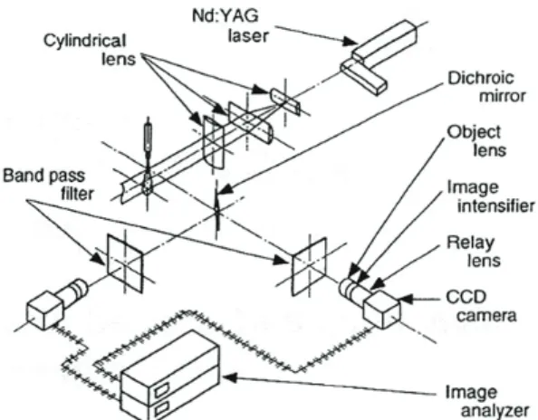
In this study, a constant volume chamber with the fuel injection system of ECD-U2(common rail-type) was used, and the evaporative spray was formed by injecting the fuel into the chamber which can realize high-temperature and high-pressure atmosphere. The diagram of the photographing optical system is shown in Fig. 1. The donut-shaped beam is shot from Nd:YAG laser(wavelength:
355nm) to make the sheet beam 50mm in width
and 0.2mm in thickness with cylindrical lens of three sheets, which is injected to the central axis of spray. The 2-D profile images of the evaporative spray obtained from the optical system are diffracted by using the dichroic mirror(D.M.) and band pass filter, and then they are amplified through an image intensifier and captured in the CCD camera before they are saved in CPU.
Fig. 1 Schematic diagram of laser sheet optical system and photography system
2.2 Experimental condition
The experimental conditions of this research were summarized in the Table 1. The ambient condition inside the chamber is the high-temperature and high-pressure atmosphere that simulated the ambience inside the cylinder at the time of the beginning of the spray from the high-speed DI diesel engine of the actual light duty as the ambient temperature Ta=700K, the ambient pressure pa=2.55MPa, and the ambient density ra=12.3kg/m3. For ambient gas, highly pure nitrogen gas(purity 99.9%) was used to prevent the oxidation of fluorescent and the ignition of the fuel. The injection nozzle was a single-hole nozzle, and the diameter and length of the hole were 0.2mm, 1.0mm(l/d=1.0mm/0.2mm), respectively. Photography was performed under injection pressure pinj=72MPa
Injection nozzle
Type : Hole nozzle DLL-p Diameter of the hole [mm] 0.2
Length of the hole [mm] 1.0
Ambient gas gas
Ambient temperature Ta[K] 700
Ambient pressure pa[MPa] 2.55
Ambient density [kg/] 12.3
Injection pressure pin j[MPa] 22, 42, 72, 112
Injection quantity Qin j[mg] 12.0
Injection duration tin j[ms] 2.82, 1.98, 1.54, 1.20 Table 1 Experimental condition in the change of injection pressure
and injection duration tinj=1.54ms. Replicability of injection was sufficiently confirmed prior to the experiment, and as a result, sufficient replicability was obtained.
3. Numerical method and condition
3.1 Numerical method
In the diesel spray, LES Smagorinsky mod is used as a turbulence model. As the studies of Tsukasa et al.2), Vourinen and Larmi3) and Drozda and Oefelein4), in spite of century-long efforts to develop RANS turbulence models, a general-purpose model suitable for a wide range of practical applications is not yet appropriate.
This is to a large extent attributable to differences in the behavior of large and small eddies. The smaller eddies are nearly isotropic and have a universal behavior(for turbulent flows at sufficiently high Reynolds numbers at least). On the other hand, the larger eddies, which interact with and extract energy from the mean flow, are more anisotropic and their behavior is dictated by the geometry of the problem domain, the boundary conditions and body forces. When Reynolds-averaged equations are used the collective
behavior of all eddies must be described by a single turbulence model, but the problem dependence of the largest eddies complicates the search for widely applicable models. A different approach to the computation of turbulent flows accepts that the larger eddies need to be computed for each problem with a time-dependent simulation. The universal behavior of the smaller eddies, on the other hand, should hopefully be easier to capture with a compact model. This is the essence of the large eddy simulation(LES) approach to the numerical treatment of turbulence.
Instead of time-averaging, LES uses a spatial filtering operation to separate the larger and smaller eddies. The method starts with the selection of a filtering function and a certain cutoff width with the aim of resolving in an unsteady flow computation all those eddies with a length scale greater than the cutoff width. In the next step the spatial filtering operation is performed on the time-dependent flow equations. During spatial filtering information relating to the smaller, filtered-out turbulent eddies is destroyed. This, and solved ones, gives rise to sub-grid-scale stresses or SGS stresses. Their effect on the resolved flow must be described by means of an SGS model. If the finite volume method is used the time-dependent, space-filtered flow
equations are solved on a grid of control volumes along with the SGS model of the unresolved stresses. This yields the mean flow and all turbulent eddies at scales larger than the cutoff width.
The non filtered Navier-Stokes equations are :
( ) 2
( i) i j i
j j j j
U U U p U
t x x x x
(1)
Where, Ui: Velocity of the component i p : Pressure
xj : x-direction of the component j μ : Viscosity
Large Eddy Simulation(LES) is about filtering of the equations of movement and decomposition of the flow variables into a large scale (resolved) and a small scale (unresolved) parts. Any flow variable f can be written such as:
f f f
(2)Where f, the large scale part, is defined through volume averaging as:
( i,) ( i i) ( , )i i
f x t
VolG x x f x t dx (3) Where is the filter function(called the hat filter or Gaussian filter).LES continuity equation
( )
i 0
j
U
t x
(4)
LES momentum equations
2 ( )
( )
( i) i j i ij
j j j j j
U U
U p U
t x x x x x
(5)
Where, U : Average velocity of the component ii
p: Average pressure
i j ij
u u
i jU U
: Sub-grid-scale(SGS) stresses Smagorinsky suggested that, since the smallest turbulence eddies are almost isotropic, we expect that the Boussinesq hypothesis might provide a good description of the effect of the unresolved eddies on the resolved flow5). It is thereby assumed that the SGS stresses are proportional to the modulus of the strain rate tensor, Sij of the filtered large-scale flow:1 1
2 3 3
j i
ij SGS ij kk SGS kk
j i
U S U
x x
(6)
where SGSis the SGS viscosity.
In the analysis of diesel spray, it is based on particle transport theory of multiphase model and the fuel particle track that is formed by the flow in the point of Lagrangian view is tracked(Lagrangian particle tracking).
Particle Translation
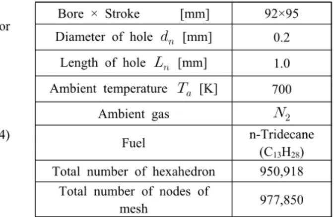
Table 2 Numerical condition in the change of ambient and injection pressure
Bore × Stroke [mm] 92×95 Diameter of hole [mm] 0.2
Length of hole [mm] 1.0 Ambient temperature [K] 700
Ambient gas
Fuel n-Tridecane
(C13H28) Total number of hexahedron 950,918
Total number of nodes of
mesh 977,850
p p
d r U dt
(7)
Where, rp
: Particle translation displacement [m]
Up
: Particle average velocity [m/s]
Particle Momentum
p p
m dU F
dt
(8) Where,
D B R VM P BA
F F F F F F F
FD
: Drag force acting on the particle [N]
FB
: Buoyancy force due to gravity [N]
FR
: Forces due to domain rotation [N]
FVM
: Virtual mass force [N]
FP
: Pressure gradient force [N]
FP
: Basset force [N]
p p
m dU dt
can be modified due to the special form of the virtual mass term.
3.2 Numerical conditions
Table 2 shows numerical condition for analysis of the diesel spray(n-Tridecane, C13H28). The numerical conditions are set for the sameas the experimental conditions.
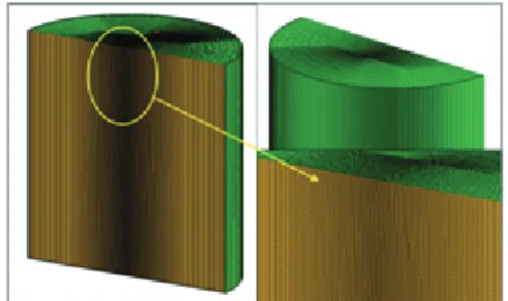
Fig. 2 Mesh structure for the analysis of the diesel spray
Fig. 2 shows the mesh structure for numerical analysis of the diesel spray. As shown in Fig. 2, to analyze the exact behavior of the spray a dense mesh was used in the central part of the mesh structure.
4. Results and discussion
4.1 Analysis of diesel free spray by exciplex fluorescence method
Fig. 3 shows the two-dimensional fluorescence intensity images of the free spray with injection pressure change obtained by exciplex fluorescence method6). In the figures, the(i), (ii) are the vapor and liquid phase of the injected fuel, respectively.
The photographing timing was set when the injected fuel mass was almost the same in the each injection pressure, that is, when t/tinj was almost equal at each injection pressure. In the each figure, the liquid phase is wider than the vapor phase in the upper region of the spray, because photographing the vapor phase, a large aperture was selected in order to reduce the halation region due to the TMPD monomer fluorescence of liquid phase. On the other hand, when photographing the liquid phase, the small aperture was selected in the optical system to capture the liquid phase region of low concentration. Consequently, the liquid phase image is larger than the vapor phase image. In Fig. 3, with increasing injection pressure, the low vapor luminance of upstream spray spreads in the radial direction. So, the atomization and evaporation of the diesel spray were promoted by the increase of shear force caused by the interaction between the injected fuel and ambient gas. The fluorescence intensity of the liquid phase rapidly decreases in the vicinity of Z=40 mm from the nozzle tip. Also, in each condition of injection pressure, the meandering flow of the mainstream region starts on the spray radial direction at the distance of Z=40 mm. As a
Fig. 3 Temporal change in the free spray image taken by exciplex fluorescence method (Qinj=12.0[mg],ra=12.3[kg/m3],Ta=700[K])
result, it could be speculated that the transition point at which the momentum of the spray interchanges with the ambient gas is, approximately, in the vicinity of Z=40 mm.
Consequently, the vortex flow of the ambient gas dominates spray development in the latter part of
the injection.
4.2 Analysis of diesel free spray by numerical method
Fig. 4 shows images of diesel spray volume that contains liquid and gas phase, and velocity marked
Fig. 4 2-D and 3-D images of diesel spray volume at the injection pressure of 72[MPa] and at the ambient pressure of 2.55[MPa] and at the time of 1.10[ms] after injection start7)
Fig. 5 3-D images of diesel spray shape and droplets and vortex structure at each time of 0.75[ms], 1.10[ms], and 1.75[ms] after injection start colored by C13H28 velocity
by vectors at the injection pressure(pinj) of 72MPa and at the ambient pressure(pa) of 2.55MPa, and at the time of 1.10ms after injection start. Axial penetration(SA) and spray angle(θ) defined in this study are also marked in Fig.4. It is observed that the spray is radially growing up, while the entrainment of the ambient gas occurs in the section of about 50mm to 70mm from the nozzle tip. Because, fuel particles atomized by interaction injected fuel and ambient gas is opposed by the
ambient gas and the momentum of the particles is getting small. Also the particles are pushed outwardly by continually injected particles. Finally, the vortex structure will be formed.
Fig. 5 shows images of the diesel spray shape and droplets, and vortex structures at each injection start and pinj of 72MPa colored by C13H28 velocity distribution. In the developmental stage of the diesel spray, it is obviously observed that the diesel fuel are thinly separated out in the shape of ligament by
the momentum difference between the diesel fuel and the ambient gas, and then droplets of the diesel fuel are finally formed. The fuel particles that are growing along the central axis of the diesel spray are less affected by the ambient gas than the particles that exist far from the central axis of the spray are done. The velocity of the fuel particles in the central axis of the spray, therefore, becomes higher than the velocity of the particles that exist far from the central axis.
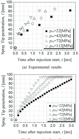
Fig. 6 shows tip penetration in the change of the injection pressure. In experimental results of the Fig. 6, the spray tip penetrations was defined by the spatial region where fluorescence intensity marked by 255 gradation of the spray’s center
(a) Experimental results
(b) Computational results
Fig. 6 Tip penetration in the change of the injection pressure
decreases to 10 % (230~255) of it value in each image. As compared the penetration of the experiment with the penetration of the computational analysis, there is a little quantitative difference between them. However, the tendency of the numerical results are the same as the experimental results.
5. CONCLUSIONS
In this study, the macro behavior characteristics(spray tip penetration and mixture formation) of diesel spray were studied at high temperature and injection pressure by using experiment and numerical analysis. The results are important to investigate the mixture formation of the injected fuel and the ambient gas. The following conclusions are drawn from this study.
In this study, the process of mixture formation before combustion has been examined with comparison and analysis of the experimental results and the numerical results. In the analysis of evaporative spray behavior of diesel fuel, the droplets, ligaments, meandering behavior are shown in the results of the analysis, when LES, Large Eddy Simulation, turbulence model in the ANSYS CFX program is used. Especially to use CFX program is useful in study for macro behavior characteristics of the diesel spray, namely, distance of the penetration tip of the spray. However, the experimental and numerical results show inconsistencies in the case of the high injection pressure and then it is necessary to improve the program, such as sub-models in the future.
Finally, since the experimental results and the numerical results are consistent with each other, the effectiveness of the use of CFX of commercial code is definitely validated for the behavior-characteristics analysis of evaporative diesel spray.
Acknowledgement
This work was supported by the Dong-A University research fund.
References
1. L. A. Melton, 1983, “Spectrally separated fluorescence emissions for diesel fuel droplets and vapor”, Applied Optics, Vol. 22, No. 14 pp.
2224-2226.
2. H. Tsukasa, K. Takahiro, J. Senda, and H.
Fujimoto, 2008, “Effect of convective schemes on LES of fuel spray by use of KIVALES”, SAE paper, No. 2008-01-0930.
3. V. Vourinen and M. Larmi, 2008, “Large-eddy simulation on the effect of droplet size distribution on mixing of passive scalar in a spray”, SAE Paper, No. 2008-01-0933.
4. T. G. Drozda and J. C. Oefelein, 2008, “Large eddy simulation of direct injection processes for hydrogen and LTC engine applications”, SAE Paper, No. 2008-01-0939.
5. H. K. Versteeg and W. Malalasekera, 2007, “An introduction to computational fluid dynamics”, Pearson Education, pp. 98-110.
6. J. K. Yeom, J. S. Park and S. S. Chung, 2005,
“An analysis on structure of impinging and free diesel spray with exciplex fluorescence method in high temperature and pressure field”, KSME Int. J.(JMST), Vol. 19, No. 12, pp. 2281-2288.
7. J. K. Yeom and M. C. Kim, 2009, “A basic study of the behavior characteristics of diesel spray and natural-gas jet”, Trans. of the KSPSE, Vol. 13, No. 6, pp. 13-21.
![Fig. 3 Temporal change in the free spray image taken by exciplex fluorescence method (Q inj =12.0[mg],r a =12.3[kg/m 3 ],T a =700[K])](https://thumb-ap.123doks.com/thumbv2/123dokinfo/5274693.636549/6.786.106.684.112.781/temporal-change-spray-image-taken-exciplex-fluorescence-method.webp)
![Fig. 4 2-D and 3-D images of diesel spray volume at the injection pressure of 72[MPa] and at the ambient pressure of 2.55[MPa] and at the time of 1.10[ms] after injection start 7)](https://thumb-ap.123doks.com/thumbv2/123dokinfo/5274693.636549/7.786.157.634.112.385/images-diesel-volume-injection-pressure-ambient-pressure-injection.webp)