Received 12 October 2015, Revised 05 November 2015, Accepted 19 November 2015
* Corresponding Author Chang-Mook Choi(E-mail:[email protected], Tel:+82-55-549-1483) Department of Navigation, Naval Academy, Changwon 51704, Korea
한국정보통신학회논문지(J. Korea Inst. Inf. Commun. Eng.) Vol. 20, No. 2 : 451~456 Feb. 2016
빔포밍 기법을 이용한 GPS 재밍 대응
최창묵*
GPS Anti-Jamming Using Beamforming Technique
Chang-Mook Choi*
Department of Navigation, Naval Academy, Changwon, 51704, Korea
요 약
GPS 위성 신호는 매우 미약하기 때문에 시스템 재밍에 노출되어 있다. 이러한 재밍은 의도적 또는 미의도적 간섭
신호 송출에 따라 발생된다. 만약 재밍 신호가 수신기로 매우 강하게 들어온다면 수신기는 자동적으로 방어할 수 있
도록 작동되어야한다. 재밍 상황에서 수신기가 정상적으로 작동할 수 있도록 하는 방법은 공간 필터링이 이용되고 있다. 본 논문에서는 재밍대응 기법으로 신호처리 방법인 빔포밍을 조사하고 사용 가능여부를 분석하였다. 재밍 신 호를 받으면 어레이 방향을 바꾸기 위하여 빔포밍은 센서 신호를 통제할 수 있기 때문에 재머 반대 방향으로 제어할
수 있는 고각 θ를 측정하였다. 측정결과 GPS 신호는 안테나가 제어각 안에 있을 때 사용가능하기 때문에 제어각 30°
까지 GPS 위치 측정이 가능하였다.
ABSTRACT
Because GPS signals are weak, system jamming is a real and present danger. This can happen when the receiver is subjected to intentional or unintentional interference by a transmitter. If the jamming signal is strong enough, the receiver can be operated to take corrective action automatically. Current methods to protect GPS receiver from jamming condition are based on spatial filtering. In this paper, the beamforming as referred to in signal processing technique used in arrays for directional signal reception was suggested and analyzed for anti-jamming. In order to change the directionality of the array when receiving a jamming signal, a beamformer can control the signal at each sensor. Therefore, cutoff angle θ was measured in the opposite direction of the jammer. GPS signals are only processed when the antenna element is within inside the cutoff angle. As a result, GPS positioning can be used in condition under cutoff angle 30°.
키워드 : 위성항법, 재밍 신호, 공간 필터링, 빔포밍, 재밍 대응
Key word : GPS, jamming signal, spatial filtering, beamforming, anti-jamming.
Ⅰ. INTRODUCTION
Recently, because many modern weapon systems depend on Global Positioning System (GPS) to achieve accuracy requirements, anti -jamming technique is becoming an important part such as Electronic warfare (EW). EW is defined as the art and science of preserving the use of the electromagnetic spectrum for friendly use while denying its use to the enemy [1, 2].
The Volpe report analyzed potential vulnerabilities of GPS and identified spoofing as a critical threat [3]. As we all know, GPS signals are weak. The minimum received power is -160, -163 and -166 dBW for C/A, L1 P(Y), and L2 P(Y) signals, respectively [4, 5].
This can happen when the receiver is subjected to intentional or unintentional radio-frequency interference by a transmitter operating on or near GPS frequencies.
If the interference is strong enough, it can jam the receiver. The jammed GPS receiver is denied position or time estimates which can be critical to the mission.
While noise jamming of the GPS receiver is a threat, the user is easily aware of its existence and characteristics. The worst case is when GPS-based navigation is denied.
When jamming signals are present in GPS receiver antenna, if possible, the receiver would be operated to take corrective action automatically using filtering techniques. Various techniques [6-8] have been adopted to avoid jamming, including frequency hopping though it requires excessive bandwidth. Spatial filtering can solve the problem over head without the need of additional bandwidth as signals are filtered on basis of their direction [9-11].
In this paper, the beamforming as referred to in signal processing technique used in arrays for directional signal reception was suggested and analyzed for anti-jamming.
To change the directionality of the array when receiving, a beamformer can control the signal at each sensor.
Therefore, cutoff angle θ was measured in the opposite direction of the jammer.
Ⅱ. BEAMFORMING TECHNIQUE
Generally, an array captures spatially propagating signals arriving from a certain direction and processes them to obtain useful information. To this end, we intend to linearly combine the signals from all the sensors in a coefficient manner, so as to estimate transmitted data radiating from a specific direction. This operation is known as beamforming [12].
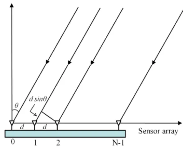
Fig. 1 A spaced linear array.
In figure 1, a spaced linear array is depicted with N identical isotropic elements. Each element is weighted with a complex weight Vk with k=0,1, ․ ․ ․ ,N-1, and the inter-element spacing is denoted as d. If a plane wave impinges upon the array at an angle θ with respect to the array normal, the wavefront arrives at element k+1 sooner than at element k, since the differential distance along the two ray paths is d sin θ.
Adding all the element outputs together gives what is commonly referred to as array factor F [11] :
sin (1)
(2)
Where is , is wave length. The phase of the kth element leads that of the (k-1)th element by α, the array factor becomes the following expression :
sin (3)
If sin, a maximum response of will result at the angle .
That is, the antenna beam has been steered towards the wave source. An example of for an sixteenth-element linear array is given in figure 2.
Fig. 2 An example of beamforming for a sixteenth- element linear array.
Ⅲ. TEST RESULTS AND DISCUSSIONS
Antenna arrays can control to steer their beam and nulls towards certain directions, which is often referred to as spatial filtering. Spatial filtering is of particular importance in electromagnetic interference condition [13, 14].
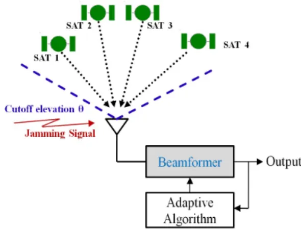
Figure 3 shows the concept of anti- jamming antenna system.
To change the directionality of the array when transmitting, a beamformer controls the phase and relative amplitude of the signal at each transmitter, in
order to create a pattern of constructive and destructive interference in the wavefront.
Fig. 3 The concept of anti-jamming antenna system.
Especially, the null steering technique can remove the jamming signal coming from a certain direction.
The GPS receiver used for this test is a novatel PROPAK-DREDGER receiver. The elevation cutoff angle for usable satellites is controlled. Therefore, satellites below the cutoff angle is eliminated for positioning. Figure 4 shows GPS positioning possibilities by analyzing the cutoff angle 5, 10, 15, 20, 25, 30 and 35 degrees.
Fig. 4 The positioning possibilities by analyzing the cutoff angle
An example, for a useful incoming signal and a jamming source located at elevation 20°, has been presented. The null steered towards jamming source cuts off the signal. That can be rejected because the elevation angle between the incoming signal direction and jamming is controlled.
(a)
(b)
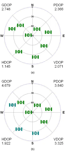
Fig. 5 The positioning DOP of GPS receiver due to (a) cutoff angle 5° and (b) 30°.
(a)
(b)
Fig. 6 The position and standard deviation of GPS receiver due to (a) cutoff angle 5° and (b) 30°.
The value of the θ angle can be determined either by using the known GPS satellite positions or measuring jamming directions. Cutoff angle θ is measured in the opposite direction of the jammer. Cutoff angle over 30°
is denied for GPS positioning.
The positioning dilution of precision (DOP) of cutoff angle 5° and 30° are presented in figure 5. The DOP parameters are shown to be functions of the receiver/
satellite geometry. It is normally represented by the geometric dilution of precision (GDOP), position dilution of precision (PDOP), horizontal dilution of precision (HDOP), and vertical dilution of precision (VDOP).
Also, GPS accuracy is generally expressed by the value of DOP. The satellite geometry effect of cutoff angle 5° was measured at the values of GDOP 2.7, PDOP 2.4, HDOP 1.1, and VDOP 2.1 and the satellite geometry effect of cutoff angle 30° was measured the values of GDOP 4.7, PDOP 3.8, HDOP 1.9, and VDOP 3.3. Therefore, GPS positioning can be used in condition under cutoff angle 30°.
Figure 6 shows the position and standard deviation of GPS receiver due to cutoff angle 5° and 30°. The standard deviation of cutoff angle 5° and 30° are LAT 1.47m/LON 1.86m and LAT 2.33m/LON 3.09m, respectively. GPS accuracy of cutoff angle 30° is less than that of cutoff angle 5°.
Ⅳ. CONCLUSIONS
Because GPS signals are weak, system jamming is a real and present danger. This can happen when the receiver is subject to interference by a transmitter. If the interference is strong enough, it can jam the receiver and deny GPS-based navigation.
Anti-jamming system of GPS has been a major concern for system security. But the usual filtering techniques are not helpful as the jamming signal and desired signal are of the same frequency. Beamforming can solve the problem over head without the need of additional bandwidth as signals are filtered on basis of their direction of arrival. Especially, anti-jamming antenna can be simultaneously controled to form a pattern null coincident with the jammer bearing.
GPS signal is passed by beamforming whenever the GPS jamming signal is under the cutoff angle θ. The value of angle θ can be determined either by using the known GPS satellite positions or measuring jamming directions. Cutoff angle θ is measured relative to the direction opposite the jammer. Cutoff angle over 30 degree is denied for GPS positioning.
Therefore, receiver can detect jamming signal and mitigate interference. The proposed beamforming
technique is to increase the efficiency for anti- jamming.
REFERENCES
[ 1 ] David Adamy, EW 101: A First Course in Electronic Warfare, Artech House, 2001.
[ 2 ] David Adamy, Introduction to Electronic Warfare modeling and Simulation, Artech House, 2003.
[ 3 ] John A. Volpe, Vulnerability assessment of the transportation infrastructure relying on the Global Positioning System, Tech. Report, Nation Transportation Systems Center, 2001.
[ 4 ] US Coast Guard Navigation Center, ICD-GPS-200, Oct.
1993.
[ 5 ] E. Kaplan, Understanding GPS: Principles and Applications, Artech House, 1996.
[ 6 ] Zdravko M. Ponos and Miroslav L. Dukic, “Analysis of GPS Receiver Anti-Jamming Characteristics,” IEICE Trans.
Commun., vol. E83-B, no. 10, pp. 2411-2418, Oct. 2000.
[ 7 ] James H. Doty, “Revolution in GPS,” GPS world, Sep.
2004.
[ 8 ] John Nielsen, Ali Broumandan, and Gerard Lachappelle,
“Spoofing Detection and Mitigation With a Moving Handheld Receiver,” GPS world, Sep. 2010.
[ 9 ] Rana Liaqat Ali, Anum Ali, and Anis-ur-Rehman,
“Adaptive Beamforming Algorithms for Anti-Jamming,”
Inter. J. Signal Processing, Image Processing and Pattern Recognition, vol. 4, no. 1, pp. 95-105, March 2011.
[10] B. Allen and M. Ghavami, Adaptive Array System:
Fundamentals and Applications, John Wiley & Sons, 2005.
[11] J. Litva and T. K. Lo, Digital beamforming in wireless communications, Artech House, 1996.
[12] Lei Wang, “Array Signal Processing Algorithms for Beamforming and Direction Finding,” Ph. D. dissertation, University of York, York, 1996.
[13] Amara Prakasa Rao, N.V.S.N. Sarma, “Adaptive Beamforming Algorithms for Smart Antenna Systems,”
WSEAS Trans. on Communications, vol. 13, pp. 44-50, 2014.
[14] Barry D. Van Veen and Kevin M. Buckley, “Beamforming:
A Versatile Approach to Spatial Filtering,” IEEE ASSP Magazine, vol. 5, no. 2, pp. 4-24, April 1988.
최창묵(Chang-Mook Choi)
1996년 해군사관학교 기계공학과 공학사 2001년 군사과학대학원 해양공학과 공학석사 2008년 한국해양대학교 전파공학과 공학박사 2008년 ~ 현재 해군사관학교 교수
※관심분야 : 전파/위성항법, 전파흡수체 개발