Vol. 21, No. 2 (2011)
125
†Corresponding author
E-Mail : [email protected] (B. -T. Lee)
Fabrication of Cross-linked Nano-Fibrous Chitosan Membranes and Their Biocompatibility Evaluation
Thi-Hiep Nguyen, Seong-Jin Lee*, Young-Ki Min** and Byong-Taek Lee
†Department of Biomedical Engineering and Materials, College of Medicine, Soonchunhyang University, Cheonan, Chungnam 330-090, Korea
*Department of Thoracic and Cardiovascular Surgery, Cheonan Hospital, Soonchunhyang University, Cheonan, 330-090, Korea
**Department of Physiology, College of Medicine, Soonchunhyang University, Cheonan, Chungnam 330-090, Korea (Received October 4, 2010 : Received in revised form November 27, 2010 : Accepted November 28, 2010)
Abstract
Fibrous chitosan membranes were fabricated as a substrate for skin applications using an electro-spinning process with different solvents and varying concentrations. Scanning electron microscopy (SEM) images confirmed that the formation of the chitosan fibrous membrane in trifluoroacetic acid was better than that in acetic acid. Fourier transform infrared spectroscopy showed that the chitosan fibers were cross-linked with glutaraldehyde, and that the cytotoxicity of the aldehyde groups was reduced by glycine and washing by NaOH and DI water. Chitosan cross-linked fibrous membranes were insoluble in water and could be washed thoroughly to wash away glycine and excess NaOH and prevent the infiltration of other water soluble bio-toxic agents using DI water. MTT assay method was employed to test the cytotoxicity of chitosan membranes during fabricating, treating and washing processes. After the dehydration of cell cultured chitosan membranes, cell attachment behavior on the material was evaluated using SEM method. Effect of the treatment processes on the biocompatibility of the chitosan membranes was shown by comparing of filopodium and lamellipodium of fibroblast cells on grown washed and unwashed chitosan fibrous membrane. The MTT assay and SEM morphology confirmed that the washed chitosan fibrous membrane increased cell attachment and cell growth, and decreased toxicity compared to results for the unwashed chitosan fibrous membrane.Key words
chitosan, electrospinning, biocompatibility, cytotoxicity.1. Introduction
Chitosan is a polysaccharide that is obtained by deacetylating chitin.
1)Chitosan is used widely in biomaterials field be- cause chitosan is formed by joining thousands of mono- saccharides which are important in living organisms.
2)This polysaccharide is nontoxic, has antibacterial properties, bio- degradability and can be further enhanced by artificial culturing.
3)Therefore, chitosan is considered in skin appli- cations recently because it has several beneficial charac- teristics such as biocompatibility, biodegradability, high efficient antibacterial action.
4,5)The electro-spinning method is one of the simplest among all methods for the preparation of fibrous membranes as extra-cellular matrices. Electro-spinning offers a new direc- tion for biopolymers since this approach allows one to decrease the diameter of the pore size from micrometers to nanometers; thereby, increasing the surface area to volume or mass ratio and the mechanical properties of the polymer.
6)The methods for fabricating chitosan electro-spun
membranes can be divided into two categories: pure CS electro-spun membranes that can be fabricated by dissolving chitosan in a pure acid, and chitosan mixed electro-spun membranes fabricated by blending with polyvinyl alcohol,
7)poly (ethylene oxide),
8)polycaprolactone,
9)etc. Chitosan electro-spun membranes are of interest in biomedical applications because they can provide a highly porous scaffold to support and guide tissue growth.
10)The highly porous nature of the nano-fiber scaffolds allows cell migra- tion and growth as well as the transport of nutrients and metabolic waste. Since the electros-spun pure chitosan fibers are dissolved in water, cross-linking the chitosan fibers is an essential step for achieving insolubility in water.
11)Glutar- aldehyde is often used as a crosslinker to improve the limited properties of chitosan, including their mechanical properties.
12)In addition, the biomineralization properties of the crosslinked chitosan materials might be influenced by the degree of glutaraldehyde crosslinking because it affects the structure and tailored surface of chitosan materials.
13)The crosslinked chitosan materials are soft and rubbery in the swollen state, resembling living tissue when immersed, and some also possess excellent biocompatibility.
14)In this work, the fabrication of electro-spun chitosan
membranes used the similar solvents, acetic acid (AA) and trifluoroacetic acid (TFA), as reported by De Vrieze et al
15)and Ohkawa K et al,
16)respectively. The aim of this work, we investigated washed an electros-pun chitosan membrane to supplement a high antibacterial substrate for skin appli- cation. The washing procedure includes washing glutaral- dehyde, acid and organic salt created during the crosslinking step. The glutaraldehyde cross-linked and uncrosslinked chitosan electro-spun nano fibrous membranes were analyzed by scanning electron microscopy (SEM) and Fourier trans- form infrared spectroscopy (FTIR). The biocompatibility of the cross-linked membrane indicated non-toxicity according to a MTT assay and fibroblasts cell well attachment through SEM images. This substrate will be coated by the hydrogel to supplement the other factors as growth factor, drug delivery system (DDS) etc… on the next investiga- tions.
2. Experimental Procedure 2.1 Materials
Chitosan (from crab shells, minimum 85% deacetylation) and glycine were from Sigma-Aldrich USA. Trifluoroacetic acid (TFA, CF
3COOH, 99.0%) and acetic acid (CH
3COOH, glacial, 99.0%) were purchased from Duksan Pure Chem- ical Co., Korea. Glutaraldehyde was obtained from DeaJung Co., Korea. Sodium hydroxide (NaOH) was supplied by SamChun Pure Chemical Co., Korea. Fetal bovine serum (FBS), P.S. (penicillin/streptomycin (antibiotics)), Dulbecco’s phosphate buffered saline (D-PBS) without calcium or mag- nesiumand, MTT solution and trypsin-EDTA were purchased from GIBCO (Carlsbad, CA). The L-929 cell line was obtained from the ATCC Cell Line (CCL-1
TM, NCTC clone 929 [L cell, L-929, derivative of Strain L], Korea). HDMS (Hexamethyldisilazane, Sigma, USA), DMSO (Dimethyl- sulfoxide 99, 0%, Samchun Pure Chemical Co., LTD, Korea), ethanol (Merck, Germany) were used as received.
2.2 Preparation of Polymer Solutions
2 wt% and 5 wt% chitosan dissolved in different acetic acid concentrations (2 and 90 wt%) and heat at 50°C. In separate solutions, 2 wt%, 5 wt%, 7 wt% and 10 wt% of chitosan were dissolved in TFA for 24 hrs and connected directly to the nozzle.
2.3 Electro-Spinning Setting
The chitosan solutions were placed in a plastic syringe (lure-lock type, 12 ml) fitted to a needle with a tip in diameter 0.25 mm. The flow rate of the chitosan solutions (0.5 ml/h) was controlled using a syringe pump (lure-lock type, Korea). The electro-spinning voltage (25 kV) was supplied directly by a high DC voltage power supply (NNC- 30 kilovolts-2 mA portable type, Korea). A grounded steel
plate located 15 centimeters away from the tip of the syringe needle was used to collect the nano-fiber membranes.
2.4 Cross linking Process and Washing Procedure The chitosan electro-spun nano-fibrous membranes were placed on aluminum foil, which were then covered with a beaker. 25% gutaraldehyde was added to the beaker, and the membranes were incubated at 37ºC for 1 hour. The electro-spun cross-linked membranes were dipped in 0.1 M glycine for 15 minutes followed by 1.0 M NaOH for 3 hours. Cross-linked samples were dissociated in a 1.0 M NaOH solution and washed 3 times with distilled water.
2.5 Characterization of Chitosan Membranes The structure of the chitosan fibrous membranes with AA and TFA was observed by SEM (SM-65F, JEOL, Japan).
The uncross-linked and cross-linked chitosan electro-spun membranes were characterized by attenuated reflectance Fourier transform spectroscopy (Spectrum GX, PerkinElmer, USA). The infrared spectra of the samples were measured over a wavelength range of 4000-500 cm
−1. All spectra were taken in the spectral range by the accumulation of 64 scans with a resolution of 4 cm
−1.
2.6 In-Vitro Study
2.6.1 Cell Line and Maintenance
The cell culture studies were carried out using L-929 mouse fibroblasts. The cells were subcultured in flasks using RPMI media, supplemented with 10% FBS and 1% P.S. and maintained at 37ºC in a humidified CO
2(5%) atmosphere (incubator, ASTEC, Japan). The cells were dissociated with trypsin-EDTA and centrifuged and resuspended in the culture medium. The culture medium was replaced every 2 days.
Gamma sterilized (SPL Life Science, Becton Dickinson Labware) 12-well tissue culture test plates was prepared before the cell culture experiments. The culture plates were then sprayed with 70% ethanol before being placed under UV light for 30 min to sterilize them. Chitosan fibrous membranes (washed and unwashed) had a circular shape, 20 mm in diameter.
2.6.2 MTT Assay/ Cytotoxicity Assay
The cellular viability and cytotoxicity of chitosan mem-
branes were determined using MTT (3-[4, 5-dimethylthiazol-
2-yl]-2, 5-diphenyltetrazolium bromide) assays. For cytoto-
xicity testing, the fibroblasts cells were seeded in 96-well
tissue culture plates at 1000 cells/well in 100 µL RPMI. Then
tissue culture plate was incubated overnight. The extraction
solutions were prepared following ISO 10933-5. Diluted
extract solutions (100 µL) of every fibrous membrane at
various concentrations (100%, 75%, 50%, 25% and 0%)
were then added. The L 929 fibroblast cells were treated for
3 days and then 20 µL of filtered MTT solution (5 mg/mL in
PBS) was added. For cell viability testing, 10 000 cells per well were seed on the electrospun membranes. After 1, 3 and 5 day (s), the chitosan electrospun membranes were changed to a new plate, then MTT solution was added on the membranes. After incubation at 37°C for 3.5 hours, MTT solution was removed from the well and DMSO was added to dissolve any insoluble formazan crystals. The absorbance was measured at 595 nm wave-length using an ELISA reader (Turner Biosystems CE, Promega Corporation, USA).
2.6.3 Adhesion, Growth Behavior of Cells
The samples were washed in PBS 1 time and medium 2 times before the cells were seeded. For cell attachment and cell proliferation analysis, the fibroblasts cells L-929 (1 × 10
4cells/cm
2) were seeded on chitosan cross-linked and cross-linked-washed nanofibrous membranes. After culturing for 1 day, the cellular constructs were harvested, rinsed twice with PBS to remove the non-adherent cells, fixed with 2%
glutaraldehyde for 30 min and washed twice with DPBS (15 min/time). Subsequently, the samples were dehydrated with a series of ethanol. Finally, the samples were washed twice with HDMS. All samples were air-dried overnight.
The dry cellular constructs were sputtered with gold using a SPI-module Sputter Coater at 7 mA for 6 minutes and examined by SEM observation.
3. Results
3.1 Fabrication of Chitosan Nanofibrous Membranes Acetic acid (AA) and TFA were used as solvents to fabricate the chitosan fibers. After examining the electro- spinning conditions, the following variables were fixed:
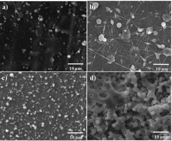
voltage 22 kV, distance 15 cm, rate of polymer solution 0.5 ml/h, and 25 gauge needle. In the case of AA, it was difficult to dissolve a large amount of chitosan. Therefore, the highest chitosan concentration was 5 wt%. In this experi- ment, different chitosan concentrations were made with different AA concentrations. Fig. 1a shows electrospun chitosan from 2 wt% chitosan in 2% AA. The image shows that only a polymer dense film was collected (no beads or fibers). The fibers contained many beads when the chitosan concentration was increased 5 wt% (Fig. 1b). Unfortunately, the same was observed when the AA concentration was increased to 90% and 2 wt% chitosan (Fig. 1c). This was more serious when the chitosan concentration increased to 5 wt% (Fig. 1d). Contrary to AA solvent, good quality fibers were obtained when TFA was used. Fig. 2 shows the SEM morphology of the chitosan electro-spun fibrous membranes with various concentrations. Clearly, beads with a small number of fibers had formed at the lowest concen- tration (2 wt%), as shown in Fig. 2a. Beads and a small proportion of fibers were observed from the solution with a
Fig. 1. SEM morphology of chitosan nano-fibrous membrane; (a) 2 wt% chitosan_ 2 wt % AA, (b) 5 wt% chitosan_ 2 wt % AA, (c) 2 wt%
chitosan_ 90 wt % AA and (d) 5 wt% chitosan_ 90 wt % AA.
slightly higher concentration (5 wt%), as shown in Fig. 2b.
However, a small proportion of fibers were observed under the same electro-spinning and concentration conditions but with 7 wt% chitosan, as shown in Fig. 2c. Ultrafine chitosan fibers were observed when the chitosan concentration was increased from 5 to 7 wt%, as shown in Fig. 2c. Beads appeared instead of ultrafine chitosan fibers with further increases in the chitosan concentration (9 wt%) (Fig 2d).
Interestingly, all chitosan fibers were cylindrical, continuous and randomly oriented at 7 wt% chitosan with 100-1000 nm fiber diameter. When the chitosan concentration was varied slightly, the as-spun fibers were not uniform or cylindrical and there was an increase in the number of beads. From these results, TFA was used as the solvent for fabricating the chitosan membranes during the electro-spinning process.
3.2 Chitosan Electrospun Nanofibers Membrane Treatments
The fibrous membranes were then cross-linked with 25% glutaraldehyde in the chamber, as described in the experimental section. The activity of the aldehyde group in the cross-linked chitosan was quenched by 0.1 M glycine and washed with distilled water. Fig. 3a presents the best chitosan fibrous membrane mentioned in Fig. 2c. Fig. 3b shows a change in morphology of the chitosan fibrous membrane from random, individual fibers and soft mem-
branes to a tie membrane with a random circular morph- ology because cross-linking bonds the individual fibers with each other in all directions. Fig. 3d displays the change in the morphology of the chitosan fibrous membranes from Fig. 3b after using glycine to quench the activity of the aldehyde group of glutaraldehyde, as this group inhibits fibroblast cell division. Fig. 3c shows a sample that had been washed with a 1M NaOH solution. Fig. 3d shows the morphology of the final product of the chitosan fibrous membranes after washing in water. The fibers can be seen more clearly than in Fig. 3c because of the removal of some organic salt resin through the washing step. The individual fibers are interconnected, making a stable chitosan mem- brane that would be viable for biomedical applications.
SEM images showed that the morphology of the CS fibrous membranes changed after each treatment period.
Moreover, after the cross-linking and washing steps, the fiber membranes retained their integrity as long, randomly oriented, cylindrical fibers. However, it is unclear if the GA vapor coated or penetrated into the fibers from the SEM images.
3.3 Characterization of Chitosan Membranes
To determine if the chitosan electro-spun fibers were
successfully crosslinked, we analyzed the FT-IR spectrum
of the bulk chitosan samples (a) and the electro-spun mem-
Fig. 2. SEM morphology of chitosan nano-fibrous membranes depend on chitosan concentration (a) 2 wt%, (b) 5 wt%, (c) 7 wt% and (d) 9 wt%.branes before (b) and after cross-linking with glutaraldehyde (c) and chitosan-glutaraldehyde with glycine treatment (d) (Fig. 4). Fig. 4a showed the transmission spectrum of the bulk chitosan with 75% deacetylation. The peaks were similar to the 78% deacetylation reported elsewhere.
24)In Fig. 4b, the FT-IR spectrum showed new peaks that could be used to determine the level of deacetylation of chitosan.
7)Figs. 4c and 4d show the spectra of the cross-linked chitosan electrospun and cross-linked chitosan electrospun
and washed. the spectra showed C = N stretching or amide I bands at 1655 and 1630 cm
−1, an amide II band at 1560 cm
−1, a bridge oxygen stretching band at 1160 cm
−1, the CH
2group of glutaraldehyde 700-740 cm
−1, and the C- O stretching bands at 1070 and 1030 cm
−1. All fibers were analyzed directly. As a result of the cross-linking reaction, there were significant differences in the FTIR spectra between the as-spun and cross-linked electrospun fibers.
The FTIR spectra of the cross-linked chitosan fibers showed a distinct change in the carbonyl-amide. FTIR showed that the chitosan fibrous membranes were successfully cross- linked; all cross-linked samples were insoluble in water.
3.4 In Vitro Study 3.4.1 Cytotoxicity Assay
The cell viability in the presence of uncrosslinked chitosan, cross-linked chitosan, crosslinked chitosan treated with glycine, and cross-linked chitosan, crosslinked chitosan treated with glycine and then washed in water were examined using a MTT assay. Fig. 5 shows the relative cell viability of the chitosan fibrous membranes in accordance with the diluted extracted solution. The results highlight the importance of the washing step. L-929 fibroblast cells were left to grow in the media for 1 day before adding the diluted extract solution, which resulted in significant varia- tions in the toxicity profiles of the singular chitosan mem-
Fig. 3. SEM morphology of chitosan nano-fibrous membranes; (a) uncrosslinked, (b) cross-linked, (c) cross-linked and treated by glycerin and (d) sample C washed in NaOH.Fig. 4. (a) FT- IR spectrum of chitosan bulk, (b) chitosan nano-fibers membrane, (c) cross-linked chitosan nano-fibers membrane and (d) cross-linked chitosan nano-fibers treated by glycine.
branes. The results showed high toxicity on the chitosan electro-spun membrane even though the chitosan bulk is biocompatible,
1)chitosan electro-spun cross-linked membrane, and chitosan electro-spun cross-linked membrane treated with glycine. In contrast, the chitosan electro-spun cross- linked membrane was washed thoroughly, and showed either low cytotoxicity or high biocompatibility. The cell viability profiles of the cross-linked chitosan membranes and those treated with glycine but not washed by DI water was considerably lower than those of the chitosan cross- linked, treated by glycine and washed in DI water. The cross-linked electro-spun chitosan was insoluble in water
but the chitosan electro-spun membranes displayed the lowest biocompatibility due to the presence of toxic agents, such as aldehyde and acid groups.
17)The chitosan electro- spun membrane showed low biocompatibility and water solubility, even though chitosan is biocompatible and insoluble. This was attributed to the residual TFA in the latter case. The MTT assay showed that carefully washed chitosan fibrous membranes can be used in biomaterial applications. The washing step is an important step because TFA is a strong acid. Although all samples were placed in a vacuum oven at low pressure for several days, some TFA still remained in the samples, as showed toxic.
3.4.2 Cells Attachment and Cells Proliferation
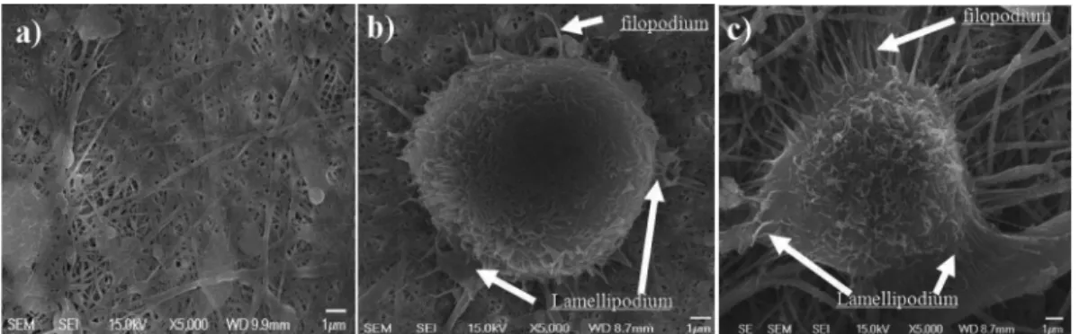
The results of the MTT assay were confirmed by the SEM images of the fibroblast cell L-929 attached to each membrane. The one cell morphology was tested to con- tinually check the biocompatibility of all chitosan mem- branes. Fig. 6a showed non-fibroblast cells attachment on the crosslinked chitosan nanofibers membrane after seeding the cell for 1 hour. The cross-linked chitosan nanofibers membrane with glycerin treatment unwashed with water (Fig. 6b) showed less filopodium and lamellipodium than on those that had been washed with (Fig. 6c). Therefore, the chitosan fibrous membranes after cross-linking and washing have high biocompatibility that is suitable for biomaterial applications.
Fig. 7 shows SEM images of L929 fibroblasts cells
Fig. 6. SEM morphology of fibroblast cells attachment for 1 hour cultured (a) cross-linked chitosan fibrous membrane; (b) crosslinked chitosan membrane treated by glycine; (c) crosslinked chitosan membrane treated by glycerin and washed by NaOH (c).
Fig. 7. SEM morphology of fibroblast cells attachment for 1 day cultured (a) cross-linked chitosan fibrous membrane; (b) crosslinked chitosan membrane treated by glycine; (c) crosslinked chitosan membrane treated by glycerin and washed by NaOH (c).
Fig. 5. Cytotoxicity of uncrosslinked and crosslinked chitosan fibrous membranes depend on glycerin treatment and washing process.
cultured for 1 day on the chitosan membranes. The fibro- blasts attached only to the crosslinked and treated chitosan membranes, but did not adhere to the crosslinked and untreated chitosan membranes. The chitosan electro-spun membranes could not be studied in-vitro because they are water soluble. The crosslinked chitosan nanofibers mem- brane showed non attachment of fibroblast cells (Fig 7a).
However, the cells retained a round shape and showed little activity on the cross-linked chitosan membranes that had not been washed with distilled water (Fig. 7b). These results confirmed that the cross-linked chitosan membrane treated by glycine was still toxic. On the other hand, on the washed cross-linked chitosan membranes, the original morphology of the fibroblasts cells changed from a round shape to an elongated one (Fig. 7c). These results are in accordance with those of the MTT assay. The electro- spun fibrous membranes provided a high specific surface area and high pore density for the cells to attach and proliferate. The SEM images showed that the fibroblasts seeded on the electro-spun chitosan membranes could integrate via the filopodium and lamellipodium.
4. Discussion
The morphology of electro-spun fibrous membranes is affected by a range of parameters, such as applied voltage, solution flow rate, distance between the capillary and collector, and the properties of the polymer solutions including concentration, surface tension, and nature of the solvent.
18)Among the parameters tested for the electro- spinning of chitosan, the conditions of for-spinning were as follows: voltage 22 kV, distance 15 cm, rate of polymer solution 0.5 ml/h, and 25 gauges needle. These conditions were determined previously by fixing each chitosan concen- tration and changing the other parameters. TFA was re- ported to be the most suitable solvent for fabricating chitosan fibrous membranes.
16)The AA is able to fabricate chitosan electrospun as reported by De Vrieze et al.
15)However, it was difficult to determine if the temperature of solution decreased, which resulted in the appearance chitosan bead instead of fibers. Fig. 1 shows SEM images that obtained for first 10-second after the start of injection.
Contrary to AA, TFA shows the fiber appeared stabilized on any environment electrospinning machine. The fibers sizes were approximately 100-500 nm after the cross-linked the fibers had conjugated with each other (Fig. 3d). The cross-linked membranes showed high biocompatibility whenever the aldehyde groups were stopped by glycine
17)and were washed due to the adverse health effects of glutaraldehyde.
19)The SEM images of the fibroblast cells adhesion to the chitosan membranes corresponded to the MTT assay. The fibroblast cells attached only on the cross- linked chitosan membranes in which the aldehyde group
had been stopped by glycine. Moreover, fibroblast cell more density was even higher when the membranes were washed with 1.0 M NaOH and distilled water. The one- cell morphology showed that the fibroblast cells L-929 attached to a final membrane via the filopodium and lamellipodium.
5. Conclusion
This preliminary study showed that TFA is the optimal solvent for fabricating chitosan fibrous membranes. The fabrication parameters, including voltage, nozzle distance, and nozzle gauge, and flow rate were optimized as follows:
voltage 22 kV, distance 15 cm, 25 gauge needle, and polymer solution flow rate 0.5 ml/h. This study demonstrated that water insoluble electro-spun fibrous chitosan membranes were fabricated successfully. The membrane showed high biocompatibility after cross-linking, glycine treatment and washing. FTIR of the cross-linked chitosan fibers showed distinct changes in the carbonyl-amide. The cross-linked membrane washed carefully showed the highest biocom- patibility according to the MTT assay. The cell adhesion and one cell morphology also confirmed that final chitosan product is useful as substrate for skin applications.
Acknowledgements
This work was supported by the Regional Innovation Center (RIC) project of the Ministry of Knowledge and Economy, Republic of Korea. (MKE-RIC060605) References
1. Q. Li, E. T. Dunn, E. W. Grandmaison and M. F. A Goosen, J. Bioact. Compat. Polym., 7, 370 (1992).
2. M. D. Johnson, Human Biology : Concepts and Current Issues, 3rd ed., p.1, Benjamin Cummings, USA (2001).
3. S. Bartnicki-Garcia and E. Reyes, Biochim. Biophys. Acta Gen. Subj., 165, 32 (1968).
4. J. J. Elsner and M. Zilberman, Acta. Biomater., 5(8), 2872 (2009).
5. S. Tokura, M. Itoyama and S. Hiroshi, Partially Sulfated Chitosan Oligomers Immobilized on Chitosan for Antithrombogenic Medical. Goods, Japan Kokai Tokkyo Koho, JP 63,89,167 (1988)
6. T. H. Nguyen and B. T. Lee, J. Mater. Sci. Mater. Med., 21, 1969 (2010).
7. U. S. Sajeev, K. A. Anand, D. Menon and S. Nair, Bull.
Mater. Sci., 31, 343 (2008).
8. C. Kriegel, K. M. Kit, D. J. McClements and J. Weiss, Polymer, 50, 189 (2009).
9. M. P. Prabhakaran, J. R. Venugopal, T. T. Chyan, L. B.
Hai, C. K. Chan, A. Y. Lim and S. Ramakrishna, Tissue.
Eng. A, 14, 1787-1797 (2008).
10. J. Venugopal, S. Low, A. T. Choon and S. Ramakrishna,
J. Biomed. Mater. Res. B Appl. Biomater., 84, 34 (2008).
11. M. N. V. R. Kumar, R. A. A. Muzzarelli, C. Muzzarelli, H.
Sashiwa and A. J. Domb, Chem. Rev., 104, 6017 (2004).
12. J. D. Schiffman and C. L. Schauer, Biomacromolecules, 8, 2665 (2007).
13. J. D. Schiffman and C. L. Schauer, Biomacromolecules, 8, 594 (2007).
14. K. Park, W. S. W. Shalaby and H. Park, Biodegradable Hydrogels for Drug Delivery, 1st ed., p.1, New York:
Technomic, USA (1993).
15. S. De Vrieze, P. Westbroek, T. Van Camp and L. Van
Langenhove, J, Mater. Sci., 42, 8029 (2007).
16. K. Ohkawa, D. Cha, H. Kim, A. Nishida and H.
Yamamoto, Macromol. Rapid Comm., 25, 1600 (2004).
17. S. P. Denyer and W. B. Hugo, Mechanisms of Action of Chemical Biocides : Their Study and Exploitation, p. 23- 28, Blackwell Scientific Publication, Oxford, UK (1991).
18. J. M. Deitzel, J. Kleinmeyer, D. Harris and N. C. Beck Tan, Polymer, 42, 261 (2001).
19. A. M. Rivers, D. J. Stephenson, K. T. Hegmann, D. R.
Lillquist and F. Derosso, Chem. Health Saf., 9(4), 13 (2002).