Nomenclature
C
sys: system resultant thrust ratio
Research Paper DOI: http://dx.doi.org/10.6108/KSPE.2019.23.1.024
이중목 노즐 개념에 기반한 유체 추력벡터제어에 관한 연구
Kexin Wu
a․ 김희동
a, *Study on Fluidic Thrust Vector Control Based on Dual-Throat Concept
Kexin Wu
a․ Heuy Dong Kim
a, *a
Department of Mechanical Engineering, Andong National University, Korea
*
Corresponding author. E-mail: [email protected]
ABSTRACT
Numerical simulations were carried out in a supersonic nozzle to investigate the possibility of using dual-throat nozzle concept in fluidic thrust vector control. Validation of the methodology showed an excellent agreement between the computational fluid dynamics results and the experimental data available, which were based on the well-assessed SST k- ω turbulence mode.
The deflection angle, system resultant thrust ratio, and thrust efficiency were investigated in a wide range of nozzle pressure ratios and injection pressure ratios. The performance variations of the dual-throat nozzle thrust vector control system were clearly illustrated with this two-dimensional computational domain. Some constructive conclusions were obtained that may be used as a reference for further studies in the fluidic thrust vector control field.
초 록
유체 추력벡터 제어에서 이중목 노즐 개념의 이용 가능성을 조사하기 위하여, 초음속 노즐에서 수치 해석을 수행하였다. 수치해석 검증에서 SST k-ω 난류모델을 사용하여 실험결과를 잘 구현하였다. 광범 위한 노즐 압력비와 분사 압력비에서 편향각도, 시스템의 전체 추력비 및 추력 효율을 조사하였다. 본 연구에서 이중목 노즐의 추력벡터제어 시스템의 성능 변화는 2차원 계산영역에서 명확하게 설명되었 다. 본 연구에서 얻어진 결과들은 유체추력벡터제어 분야에 중요한 기초자료를 제공할 것이다.
Key Words: Fluidic Thrust Vector Control(유체 추력벡터제어), Dual-throat(이중목), Supersonic Flow(초음속 유동), Deflection Angle(편향 각도), Shock Wave(충격파)
Received 20 June 2018 / Revised 3 January 2019 / Accepted 6 January 2019 Copyright Ⓒ The Korean Society of Propulsion Engineers pISSN 1226-6027 / eISSN 2288-4548
[ 이 논문은 한국추진공학회 2018 년도 춘계학술대회 (2018. 5. 30- 6. 1, 라마다프라자 제주호텔 ) 발표논문을 심사하여 수정 ․ 보완한 것임 .]
This is an Open-Access article distributed under the terms of the Creative Commons Attribution Non-Commercial License(http://creativecommons.org
/licenses/by-nc/3.0) which permits unrestricted non-commercial use, distribution, and reproduction in any medium, provided the original work is properly cited.
F
ideal: ideal isentropic thrust
F
I,i: ideal isentropic thrust of injected flow F
I,p: ideal isentropic thrust of primary flow F
x: axial force
F
y: normal force H : throat height
H
t1: upstream throat height of the nozzle H
t2: downstream throat height of the nozzle IPR : injection pressure ratio, IPR=P
i/P
bL : length of dual-throat nozzle cavity m
p: mass flow rate of the primary flow m
i: mass flow rate of the injection flow NPR : nozzle pressure ratio, NPR=P
0/P
bP
0: stagnation pressure
P
b: ambient pressure
P
e: area-weighted average static pressure of the dual-throat nozzle exit
P
w: static pressure along the upper wall R : gas constant
T : temperature
T
0: stagnation temperature
X : distance along the horizontal direction
: ratio of specific heats
: thrust efficiency
: deflection angle
: upstream divergent cavity angle
: downstream convergent cavity angle
1. Introduction
In recent decades, the fluidic thrust vector control (FTVC) is growing a more and more important technique to redirect the thrusts of the air vehicles. A lot of benefits are obtained, such as the replacement of complex mechanical parts, better maneuverability and perfect control effect[1-3]. The aircraft with the FTVC technique can take off and land at a very short distance on an aircraft carrier.
Herbst[4] guessed that the FTVC will be the
most promising development direction in the future. Moreover, Chambers[5] illustrated that this FTVC technique can be used to maintain the excellent control effectiveness under stalled operating conditions. A series of methods are utilized in FTVC field to control the deflection degree of primary jet, such as shock vector control (SVC), co-flow or counter-flow thrust vector control (Co- or Counter-FTVC), throat- shifting thrust vector control (TSTVC), and dual-throat nozzle thrust vector control (DTNTVC). Deng et al.[6-7] utilized the shock wave to carry out the studies of the FTVC and reported the effects of some factors as follows: NPR, injection location, and bypass flow ratio. However, the induced shock waves always reduce the system resultant thrust ratio. Deere[8] demonstrated that throat-shifting technique could offer a larger system resultant thrust ratio, but the deflection degree is very less compared with SVC method. Wu et al.[9]
investigated the counter-flow TVC method and illustrated that it can generate very large deflection angle with less secondary mass flow ratio, but it is difficult to address the problems of suction supply sources.
In this paper, the DTNTVC technique is
investigated emphatically due to the higher
thrust vector efficiency without sacrificing
other performance than other fluidic thrust
techniques. Actually, the dual-throat technique
was developed from the throat-shifting method
for improving the boundedness[10]. An
experiment was carried out at the NASA
Langley Research Center and some reliable
experiment data were obtained by Flamm et
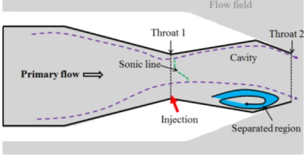
al.[11]. The sketch of the DTNTVC system is
shown in Fig. 1. It can be seen that the
recessed cavity is situated between the
upstream throat (Throat 1) and downstream
throat (Throat 2), and an injector is located at
Fig. 1 Sketch of the dual-throat.
the upstream throat. The primary flow is skewed by the injected flow and separated region is formed below the cavity.
2. Computational domain
The experimental and computational models with detailed geometry dimensions are depicted in Fig. 2. The experimental setups were established at the NASA Langley Research Center and the tests were conducted at static conditions in the Jet Exit Test Facility [11]. As shown in Fig. 2(a), the dual-throat nozzle is installed within the test devices to conduct the experiment. The identical nozzle with detailed dimensions utilized in the numerical simulations is shown in Fig. 2(b).
The second convergent part of the dual-throat nozzle is designed according to the same throat dimension of traditional C-D nozzle and the cavity is formed between two throats. The physical dimensions of upstream and downstream throat heights are Ht1=Ht2=29.21 mm. The length of the cavity L=76.20 mm.
The divergent and convergent ramp angles of the cavity are 10° and 20° respectively. A secondary flow is injected at the upstream throat, which is from an injection slot with the width of 0.55 mm. The injection angle is set as 150° in all simulations.
a) Experimental model
b) Computational model
Fig. 2 Experimental and computational models of the dual-throat nozzle.
The commercial software ANSYS Fluent 17.1 was used as the solver and Gambit was utilized to create the 2D computational domain and mesh. The working gas was air assumed as an ideal gas. Viscous flows were calculated by resolving Navier-Stokes equations. Second order accuracy was selected to reveal the details of the flow-field as much as possible.
The boundary conditions in present numerical simulations are clearly shown in Fig. 3.
Pressure inlet was used to define the
boundaries of the primary flow inlet (P
0) and
injected flow inlet (P
i). The exit boundaries of
the computational domain were set as the
pressure outlet (P
b=1 atm). The stagnation
temperature was kept at 300 K. The mass flow
rates of the pressure inlet and outlet were
monitored. As the difference of the mass flow
rate is less than
, the case can be judged
as the convergent solution.
3. Results and discussions
3.1 Validation
The methodology is validated with the experimental data of Flamm et al.[11] reported in the literature. In compressible gas dynamics field, the SST k- ω turbulence model is recognized as the most suitable to conduct the simulations for various supersonic flows. Deng et al.[6] conducted the simulations of SVC with SST k- ω turbulence model and validated well with the experimental result. Shi et al.[12]
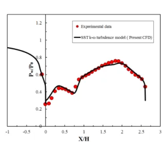
carried out the validation with all kinds of turbulence models and illustrated that the SST k-ω turbulence model gives the best agreement with the experimental data. Thus, the SST k- ω turbulence model is selected to validate the experimental data in this paper. As depicted in the Fig. 4, normalized pressure distribution along the upper wall of the dual-throat nozzle is compared with the experimental data at NPR=4, IPR=7.6. It can be observed that the SST k- ω turbulence model shows an accurate prediction in agreement with the experimental data available. Therefore, the SST k- ω turbulence model is used for further simulations.
In order to provide insight into the internal flow characteristics, Fig. 5 depicts the comparison between the experimental shadowgraph image and density contour from the CFD result at NPR=4, IPR=7.6. The experimental shadowgraph image illustrates that the mainstream attaches to the upper wall of the cavity and shock waves are formed in the vicinity of the upstream nozzle throat. The sonic line is skewed and separation region is formed at the bottom of the cavity, which result in the deflection of mainstream. In addition, some shock waves are existed at the exit of dual-throat nozzle. Compared with the density contour of the present CFD result, it is evident that the present simulations can predict the performance variation accurately.
3.2 DTNTVC performance at various NPRs
In this section, the performances of the DTNTVC system are studied at various NPRs by keeping the IPR constant at 7.6.
In Fig. 6, it depicts the variation of performance parameter in terms of deflection angle by changing the NPR value. At IPR=7.6, Fig. 3 Computational domain and boundary conditions.
Fig. 4 Comparison of upper wall pressure distributions
between the CFD result and the experimental
data.
different NPR values from 2 to 6.5 are varied.
The calculated deflection angle is defined as follow:
tan
(1)
Firstly, present CFD result is compared with the exclusive thrust vector angle acquired from the experimental data [11]. The deflection angle calculated by Eq. 1 is fitting perfectly with the experimental data available. In addition, the deflection angle is found to be decreasing with the increase of NPR value and it reaches the maximum value at NPR=2. The power of primary flow becomes stronger with the increase of NPR value. Moreover, the deflection degree of the skewing sonic line becomes weaker with the increase of NPR value. Hence, the deflection degree is smaller with the increase of NPR at the fixed IPR value.
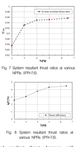
In Fig. 7, it can be clearly seen that system resultant thrust ratio increases with the increase of NPR at IPR=7.6. The system resultant thrust ratio is given as follow:
(2)
Even though the ideal isentropic thrust (F
ideal) increases with the increase of NPR value, the more rapid increase of real resultant thrust results in a larger system resultant thrust ratio at higher NPR value based on the Eq. 2. The lowest level is obtained at NPR=2, but the proportion of real resultant thrust is more than 85% of the ideal thrust. The excellent thrust vector performance is proved
based on the dual-throat nozzle vector control technology.
A comparison on the thrust efficiency at various NPRs is presented in Fig. 8. The definition of the thrust efficiency is given as:
∙
(3)
It means that the effective thrust vector angle caused by per unit injected flow increases with the increase of the NPR value.
In addition, the highest thrust efficiency is gained at NPR=6.5 when the IPR value is fixed at 7.6.
3.3 DTNTVC performance at various IPRs
In this section, the performance of the DTNTVC is studied at various IPRs by keeping the NPR value constant at 4.
The performance of the DTNTVC in terms of thrust vector angle is reported in Fig. 9.
The positive value represents the positive deflection (Y+ direction) and the negative value means the opposite deflection (Y- direction). For the validation of deflection angle, the present CFD result gives an excellent agreement with the experimental data available. For all the operating conditions, deflection angles are positive except for IPR=2.
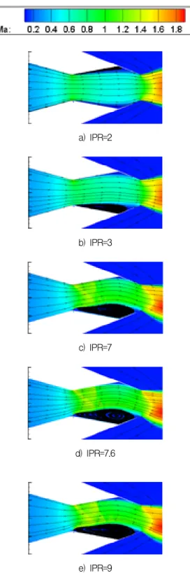
At IPR=0, there is no injected mass flow rate from the injector, which cannot result in any deflection degree. The deflection angle increases rapidly with the increase of IPR value, while 2<IPR<7. Then it follows by a smooth enhancement. Combined with the Mach number contours and streamlines as shown in Fig. 12, these variations can be explained very well. It can be observed that the separation region is located at the top of
∙