Journal of the KSTLE Vol. 27, No. 4, August 2011, pp. 209~212 The Korean Society of Tribologists & Lubrication Engineers
209
정전용량 프로브 크기에 대한 엔진오일 상대 유전율 측정
김기훈†·김영주‡ 홍익대학교 전자 전기 공학과
Measurement Of The Engine Oil Relative Dielectric Constant With Respect To Capacitive Prove Dimension
Ki hoon Kim† and Young ju Kim‡
Dept. of Electronics and Electrical Engineers Hongik University (Received April 12, 2011; Revised June 13, 2011; Accepted June 15, 2011)
Abstract − The capacitive application(prove) can be used to measure the complex permittivity of dielectric material of various thickness and cross section. This paper presents that we designed the analysis system of engine oil permittivity to know the relation between the engine oil deterioration and the prove dimension. Each of the dimension of capacitive prove is changed and then electric capacity is measured by LCR {Inductance(L), Capacitance (C), and Resistance (R)} meter. The engine oil permittivity has extracted in the prove measurement . As the additional research, this paper suggest the best of the prove dimension for the permittivity measurement.
Keywords − capacitive application(정전용량 응용), prove dimension(프로브 크기), oil deterioration(오일 열화), complex permittivity(복소 유전율), engine oil(엔진 오일)
1. 서 론
엔진오일의 내구성을 나타내는 수명이나 사용한계는 산화 및 이물질의 유입에 따라 정해지게 된다. 이는 양질 의 엔진오일이라 할지라도 사용 중에 변질되어 그 성질 이 저하되는 열화현상이 나타나기 때문이다. 엔진오일의 열화 중 가장 큰 원인은 공기 중의 산소에 의한 산화작 용이며, 산화속도는 온도, 촉매, 공기와 접촉하는 엔진오 일의 종류 및 첨가물의 종류에 따라 달라진다. 엔진오일 이 산화되면 케톤, 알데히드, 알코올 등과 같은 유용성의 산소화합물이 먼저 생성되고 다음으로 이것이 유기산으 로 바뀌며, 최후에는 오일에 용해되지 않는 수지상의 물 질이 생성 된다[1]. 실험에 의하면, 엔진 오일이 열화 될 수록 유전율과 전기 전도도가 증가함이 밝혀졌다[2].
엔진 오일의 전기적인 특성인 유전율과 전기 전도도
의 변화와 밀접한 관계가 밝혀 지면서 최근에는 엔진 오일의 전기적 특성을 측정하여 엔진오일의 상태를 감 지하는 연구가 진행중이다[3]. 엔진오일의 열화 정도에 따른 유전율을 측정하는 방법에는 여러 가지 방법이 있 지만 본 실험에서는 정전용량을 이용하여 유전율을 산 출하는 실험을 하였다. 정전용량을 이용한 프로브의 설 계에는 크게 두 가지가 고려된다. 첫 번째로는 프로브 의 형태와 크기, 물질의 전기적인 성질, 필드의 크기 그리고 신호/파워밀도이다. 두 번째로는 입력/출력에서 의 전압, 전류, 주파수, 임피던스이다. 이 두 가지는 실 제적으로 수치해석과 유한 요소 방법을 이용하여 상관 관계를 얻을 수 있다. 본 논문 에서는 프로브의 크기와 전극사이의 간격에 따라서 정전용량과 유전율의 관계가 어떻게 되는지에 대해서 설명한다.
2. 유전율 측정의 이론적 고찰
2-1. 용량성 프로브의 구조
†주저자 : [email protected]
‡책임저자 : [email protected]
210 김기훈·김영주
Journal of the KSTLE
엔진오일의 유전율을 측정하기 이전에 각각 다른 정 전용량을 가지고 있는 프로브를 설계하였다.
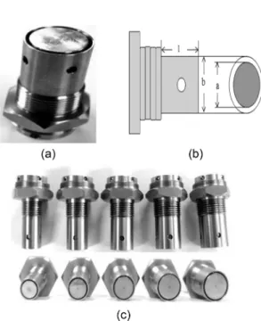
Fig. 1은 프로브의 구조도 이며, Table 1은 프로브의
크기 변화를 나타낸다. 그리고 Fig. 2는 내부 전극 크 기의 변화에 따른 구조도이며, Table 2는 전극거리에 따른 프로브의 크기를 나타낸다.
2. Parallel-plate Applicator of the E-field and Impedance/Admittance Method
평행평판으로 구성된 프로브는 수치적인 기술 중에 하나인 유한요소 방법을 적용하여 분석 할 수 있다. 평 행 평판 모델은 일차 함수 형태의 Laplace equation의 해를 통하여 유전범위에 따른 전위 함수를 산출한다[4].
실제로 프로브가 오일에 삽입 되었을 경우는 Fig. 3
과 유사하다. 하나의 복소 유전 물질 을
가지고 있다는 가정하에, Resistance와 Capacitance를 구하면 다음과 같다.
(1)
(2)
여기서 이다. 만약에 (D=h or β=1)이면
(3) ε ε= 0(εr–jεr)
R d
ε0ε''rwA
--- β 2ε'r(1–β) ε'( r2+ε''r2)1 β--- 1( –β)2
+ +
=
C ε0ε'rA ---d
β 1ε'r
--- 1( –β) ε'r2 ε''r2
( + ) +
β 2ε'+ r2β 1 β( – ) ε'+( r2+ε''r2) 1 β( – )2 ---
•
=
β h d= ⁄
R d
ε0ε''rwA ---
= Fig. 1. The prove of inner and outer electrodes, (a)
capacitive prove, (b) schematic of capacitive probe, (c) differential dimension of prove.
Table 1. The inner and outer different dimension of capacitive probe
probe a(mm) b(mm) l(mm)
1-1 14 16 17.7
1-2 16 18 17.7
1-3 18 20 17.7
1-4 20 22 17.7
1-5 22 24 17.7
Fig. 2. The inner electrode of differential dimension in prove.
Table 2. The inner electrode of differential dimension in prove
probe a(mm) b(mm) l(mm)
2-1 14 24 17.7
2-2 16 24 17.7
2-3 18 24 17.7
2-4 20 24 17.7
1-5 22 24 17.7
Fig. 3. (a) Parallel-plate applicator with partially filled lossy dielectric. (b)Equivalent circuit.
정전용량 프로브 크기에 대한 엔진오일 상대 유전율 측정 211
Vol. 27, No. 4, August, 2011 (4)
단면적 A=2πrl, d=b−a이고, a, b, r, l은 프로브 의 구조로 결정된다.
수식(3)과 (4)에서 Resistance와 Capacitance의 등가 회로로 표현되며 이는 Fig. 3-b에서와 같다. 따라서 식 (4)을 이용하면 물질의 유전율을 계산 할 수 있다.
3. 실험 과정 및 유전율 측정결과 비교
3-1. 실험 과정(experiment)
Fig. 3은 실제 실험에 사용된 LCR미터와 용량성 프 로브를 보여 준다. 프로브는 내부 구조물(황동)과 외부 의 원통(stainless steel)으로 구성되어 있다.
내부 구조물과 외부 구조물 사이에 오일이 채워질 수 있도록 내부 구조물이 외부 구조물 보다 2 mm 작 게 설계 하였다. 전극 간격 사이로 원할한 오일 유입 을 위해 그라운드 구조물에 둘레 4 mm의 원형구멍 4 개를 뚫어 넣었다. Fig. 1의 구조와 같다.
프로브의 정전용량을 측정하기 위해 Delta United Instrument사의 Du-6000 LCR{Inductance(L), Register(R), Capacitance(C)} meter를 사용하였다.
측정한 엔진오일의 상태는 가솔린 엔진으로, 사용하 기 전의 깨끗한 엔진오일(oil A)과 약 1년 정도 사용하 여 교환시기가 된 폐오일(oil B) 2가지 상태의 엔진오일 을 준비하였다. 각각의 오일은 동일한 실온(25oC) 조건 에서 측정 되었으며, LCR{Inductance(L), Register(R), Capacitance(C)} meter의 측정 주파수는 1 kHz로 하 였다.
3-2. 유전율 측정결과
프로브의 크기와 프로브의 내부 구조물의 크기에 따 C ε0ε'rA
---d
=
Fig. 3. LCR meter and capacitive prove.
Table 3. The capacitance related with differential dimension of the inner and outer prove (a) The permittivity realated with differental capacitance (b)
주파수측정 probe C(깨끗한
오일) C(더러운
오일) 오차율
1 kHz 1-1 15.5 pF 17.6 pF ±2%
1 kHz 1-2 18.0 pF 20.1 pF ±2%
1 kHz 1-3 20.4 pF 22.4 pF ±2%
1 kHz 1-4 22.5 pF 24.7 pF ±2%
1 kHz 1-5 24.65 pF 27.14 pF ±2%
(a)
prove 유전율
(깨끗한 오일) 유전율
(더러운 오일)
1-1 1.3628 1.5475
1-2 1.8087 2.0097
1-3 2.3061 2.5322
1-4 2.8262 3.1025
1-5 3.4058 3.7499
(b)
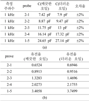
Table 4. electric capacity related with differential dimension of the inner prove (a) The permittivity realated with differental capacitance (b)
주파수측정 probe C(깨끗한 오일)
C(더러운
오일) 오차율
1 kHz 2-1 7.42 pF 7.9 pF ±2%
1 kHz 2-2 8.87 pF 9.47 pF ±2%
1 kHz 2-3 11.75 pF 13 pF ±2%
1 kHz 2-4 16.14 pF 17.32 pF ±2%
1 kHz 1-5 24.65 pF 27.14 pF ±2%
(a)
prove 유전율
(깨끗한 오일) 유전율
(더러운 오일)
2-1 0.6524 0.6946
2-2 0.8913 0.9516
2-3 1.3283 1.4696
2-4 2.0273 2.1755
1-5 3.4058 3.7499
(b)
212 김기훈·김영주
Journal of the KSTLE
라 LCR meter로 측정된 정전용량과 측정된 유전율은 다음과 같다(Table 3, 4).
Resistance값은 상대적으로 큰 값으로 출력되었기 때 문에 정확한 값을 측정할 수 없었다. 따라서 측정된 Capacitance(C)값을 추출하였고, 유전율 계산은 MATLAB[5]을 이용하였다.
식(4)에 따라서 측정된 캐패시턴스 값을 이용하여 오 일의 유전율을 계산한 결과, 구조에 따라 유전율 값이 다르게 산출되었다. 이는 식(4)에 대한 근사식 오차로 생각 되어 지며, 유전율의 차이로 오일의 상태를 측정
할 수 있다고 생각한다.
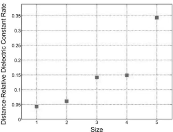
Fig. 4와 Fig. 5는 Table 3과 Table 4에서 측정된 깨끗한 오일의 유전율과 더러운 오일의 유전율의 상대 크기를 그래프로 표현한 것이다.
4. 결 론
본 연구에서는 프로브의 내부 구조물 크기 변화와 프로브 외부/내부 크기 변화에 따라 폐오일과 깨끗한 오일의 상대적인 유전율 크기비에 대한 결과를 보여 준다.
측정된 결과에 의하면, 내부 거리가 가까울수록, 프 로브 크기가 클수록 더러운 오일과 깨끗한 오일의 유 전율 크기비가 커지는 것을 볼 수 있다. 따라서 민감 한 정전용량 프로브를 설계시 더러운 오일과 깨끗한 오일의 상대유전율 크기의비가 큰 것을 선택해야 한다.
정전용량 프로브는 저렴하고, 측정하기 쉬우며, 민감 도가 높은 장점을 가진다.
후 기
이 논문은 2008년도 홍익대학교 학술 연구 조성비 에 의하여 연구되었으며 이에 감사드립니다.
참고문헌
1. C.Pu et al, IEEE Photonics Technol. Letters, Vol. 12, No. 12, pp. 1665-1667, 2000.
2. Jangannathan, S and Raju, GV.S. “Remaining Use- ful Life Prediction of Automotive Engine Oils Using MEMS Technologies,” American Control Confer- ence, 2000. Proceedings of the 2000, Vol. 5, pp.
3511-3512, 2000.
3. Simon S. Wang, and Yingjie Lin, “A New Technique for Detecting Antifrreze in Engine Oil During Early Stage of Leakage,” Sensors and Actuators B: Chemi- cal, Vol. 96, Issues 1-2, 2003.
4. Mehrdad Mehdizadeh, PhD Wilmington,Delaware.,
“Microwave/RF Applicators and Probes For Material heating, sensing and plasma generation,” ELSEVIER, pp.79-81, 2009.
5. MATLAB (matrix laboratory) is a numerical com- puting environment and fourth-generation program- ming language.
Fig. 4. prove dimension related with the deteriorated and clean oil of relative dielectric constant (X: size, Y:
relative dielectric constant).
Fig. 5. prove electrode distance realated with deteriorated oil and clean related relative dielectric constant (X: electrode distance, Y: relative dielectric constant).