• 검색 결과가 없습니다.

Time Complexity Measurement on CUDA-based GPU Parallel Architecture of Morphology Operation

N/A
N/A
Protected

Academic year: 2021

Share "Time Complexity Measurement on CUDA-based GPU Parallel Architecture of Morphology Operation"

Copied!
9
0
0

로드 중.... (전체 텍스트 보기)

전체 글

(1)

Time Complexity Measurement on CUDA-based GPU Parallel Architecture of Morphology Operation

Yonny S. Izmantoko

, Heung-Kook Choi

††

ABSTRACT

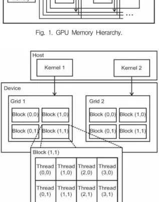
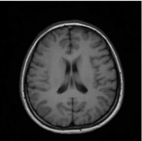
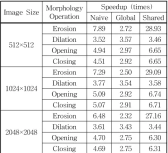
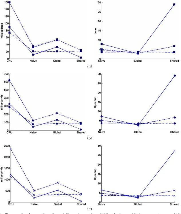
Operation time of a function or procedure is a thing that always needs to be optimized. Parallelizing the operation is the general method to reduce the operation time of the function. One of the most powerful parallelizing methods is using GPU. In image processing field, one of the most commonly used operations is morphology operation. Three types of morphology operations kernel, naïve, global and shared , are presented in this paper. All kernels are made using CUDA and work parallel on GPU. Four morphology operations (erosion, dilation, opening, and closing) using square structuring element are tested on MRI images with different size to measure the speedup of the GPU implementation over CPU implementation.

The results show that the speedup of dilation is similar for all kernels. However, on erosion, opening, and closing, shared kernel works faster than other kernels.

Key words: Time complexity measurement, GPU parallel architecture, Morphology operation, CUDA, MRI images.

※ Corresponding Author : Heung-Kook Choi, Address : (621-749) Dept. of Computer Engineering, UHRC, Inje University, Injero 197, Gim-Hae, Gyeong-Nam, Korea TEL : +82-55-320-3437, FAX : +82-55-322-3107, E-mail

: [email protected]

Receipt date : Dec. 31, 2012, Revision date : Jan. 25, 2013 Approval date : Jan. 29, 2013

††

Department of Computer Engineering, Inje University, Korea

(E-mail: [email protected])

††

Department of Computer Engineering, UHRC, Inje University, Korea

※ This research was supported by Basic Science research Program through the National research Foundation of Korea (NRF) funded by the Ministry of Education, Science and technology (2012-0002646).

1. INTRODUCTION

Morphology operation is an operation that works on image shape and form instead of the pixel intensity. The term mathematical morphology is usually used to express the set theory. Sets in mathematical morphology represent the shapes which are manifested on binary or gray tone images. The set of all the black pixels in a black and white image, (a binary image) constitutes a complete description of the binary image [1]. In im-

age processing and computer vision field, mathe- matical morphology is defined as a set of oper- ations that works on any types of image.

There are two main types of image where mor- phology operations can be applied, gray scale and binary image. Gray scale image is a type of image that has 2

n

intensity level, where n is a range of integer from 2 to 8. Binary image is image that only has two types of pixel value, black and white, which usually expressed as 0 and 1. It is possible to obtain binary image from gray scale image using threshold operation. It works by setting the pixel value below the threshold value to 0 and the pixel value above the threshold value to 1 (1).

(1)

A(x) and B(x) are input image and output image,

respectively, and t is the threshold value. The

threshold value can be determined manually or

automatically. In manual mode, threshold value is

defined and adjusted until the output image is

satisfying. On the other hand, automatic mode

tends to get the threshold value based on parame-

(2)

ters of the image. Several automatic threshold methods have been made introduced; Otsu in- troduced threshold method that minimizes the intra class variance [2], Li introduced minimum cross entropy threshold method [3], JN Kapur, et al. used maximum entropy threshold method [4], and Prewitt, et al. introduced minimum threshold method [5]. Each of this method has its own func- tion and specific application; therefore there is no threshold method that can work well for all types of image.

The morphology operations consist of two basic operations; erosion and dilation. The other oper- ations, opening and closing, that are based on them.

There are many applications field of morphology operation, such as brain segmentation of MR image [6] and cell segmentation [7]. Morphology oper- ations work using structuring element, which is a small binary image used as shape mask in basic morphological operations. Structuring element can be any shape and size, and they must have an ori- gin (usually it is the center pixel). The function of this origin is as reference pixel to write the out- put value. Shapes that are commonly used are square, hexagon, circle and disk [8]. The erosion operation is denoted as A⊖B, where A is the bina- ry image and B is the structuring element. It is expressed by (2). This equation means that erosion is the set of all points z such that B, translated by z, is contained in A.

(2) On contrary, dilation operation is denoted as A⊕

B and expressed by (3). It means that dilation is the set of all displacements z, such that B and A overlap by at least one pixel.

(3) Opening and closing are combinations of erosion and dilation. Opening is erosion operation followed by dilation operation (4), whereas closing is dilation operation followed by erosion operation (5).

(4)

(5)

2. METHODS

2.1 GPGPU and CUDA

Graphics Process Unit (GPU) was commonly used for graphics rendering and display on monitor.

Nowadays, GPU is not only used for display pur- pose but also for computation, which is called as GPGPU (General Purpose Graphic Processing Unit). There are many computations that are al- ready applied on it. GPU is well-suited for prob- lems that can be expressed as data-parallel com- putations–the same program or function that is executed on many data elements in parallel–with high arithmetic intensity. Some specific algorithms such as genetic [9], Smith-Waterman [10] and connected component labeling [11] have been im- plemented using GPU. Because of this parallel computation utility, NVIDIA introduced CUDA (Computed Unified Device Architecture) in 2006 [12]. CUDA is a general purpose parallel computing architecture–with a new parallel programming model and instruction set architecture–that en- ables NVIDIA GPUs to solve many complex com- putational problems more efficiently than CPU. It also comes with programming environment of CUDA C, a C-like programming language that is easier to be understood and learned than many un- familiar rendering code and syntax such as OpenGL or OpenCL.

GPU consists of several types of memory. Their

hierarchy can be seen on Fig. 1. Each memory has

its specific usage and characteristics, such as

speed, size, etc. Fig. 2 shows the hierarchy of

thread, block, and grid. CUDA documentation

made by NVIDIA stated that the fastest memory

on GPU is shared memory, which is located on

GPU chip. This memory is accessible for all

threads in one block [13]. The smallest part of

GPU is called thread and the parallel computation

takes place on it. Kernel, which is a set of com-

(3)

Fig. 1. GPU Memory Hierarchy.

Fig. 2. CUDA Grid-Block-Thread Organization.

Fig. 3. 3×3 structuring element.

mands or functions, will be executed parallel on each thread on GPU.

In this paper, we propose architectures for ero- sion and dilation operation on GPU using CUDA.

There are 3 types of architecture that we propose, naïve, global, and shared. Each of these archi- tectures has different way to access the pixel value of the input image. These architectures are tested on several images with different size to get the speed on each of them. The remainder of this paper is organized as follows: In section 2 we describe the architecture for erosion and dilation. In section 3, we will test the architectures on several images and compare the results. Finally, we conclude this work in section 4.

2.2 PROPOSED ARCHITECTURE

As mentioned in the previous section, morphol- ogy operation works by sliding the structuring ele- ment on every pixel in input image. In sequential mode, the structuring element will slide to the right until the end of row, and then it will go to the lower row and repeat the same sliding process. The mor- phology operation works differently compared by filtering operation where the parallel process is done by separating the filter into row and column operations. In morphology operation, structuring element works as one unit that cannot be separated into row and column operations. Therefore, in par- allel morphology operation, we should make sev- eral structuring element at the same time and do the morphology operations in parallel. To simplify the comparison, a square structuring element and same image were used.

2.2.1 Naïve Kernel

This kernel works only on global memory. Here, the index of pixels must be defined manually.

Therefore, the size of structuring element is also limited to the defined size. For example, if the size of structuring element which is defined only 3×3, 4×4 and 5×5, we cannot use other sizes of structur- ing element, unless we redefine the kernel itself.

This is the limitation of naïve kernel.

Index of a thread is defined by the number of

threads per block, image width, block index for

x-y, and thread index for x-y. Structuring element

which maximum size is 7×7 is defined for this

kernel. Fig. 3 is an example of structuring element

which size is 3×3. Before defining the pixel index,

we need to define 2D index in x and y (6). The

(4)

center pixel index, i4, is defined as (7) and the index of pixels around it is determined by respect of the center pixel index [14]. For example, index of the bottom right pixel, i8, is defined as (8).

(6) (7) (8) In erosion, this kernel checks all pixel values within the structuring element. If all of the pixel values are 1, then this kernel will assign 1 on the center pixel of the output image. In dilation, if the pixel value in input image is 1, then this kernel write assign 1 for all pixels within the kernel size on the output image.

2.2.2 Global Kernel

This kernel also works only on global memory.

The difference between global kernel and naïve kernel is the way to define the index of pixels. 2D index is still defined by (6), but a new parameter, RADIUS, is introduced in order to define the pixel index automatically. Change in RADIUS means change in structuring element size, and it also changes the index of pixels.

For erosion operation, another parameter called COUNTER is introduced. This parameter is used to count the number of pixel which value is 1 in the input image. The global erosion kernel checks the pixel values within the RADIUS. Each time an object pixel (which value is 1) is found, COUNTER will increase its value by 1. After all pixels within the RADIUS are checked, this kernel will assign 1 to the center of the output image if and only if the COUNTER value meets a specific condition.

This condition is described in Fig. 4. This figure shows the erosion kernel that consists of 4 areas with white color, 4 areas with gray color and 1 center pixel which color is black. This is the final condition of COUNTER that must be fulfilled.

Therefore, COUNTER must equal to (9) before as-

signing 1 on the center of the output image.

(9)

Fig. 4. Condition of COUNTER.

Dilation operation works by the simpler way.

This kernel will read all pixels in the input image one by one. If the pixel value is 1, then this kernel will assign 1 within the RADIUS in the output image.

2.2.3 Shared Kernel

Unlike naïve kernel and global kernel that work only on global memory, shared kernel works on both of global and shared memory. Shared memory is often used to hold the portion of global memory data that are heavily used in an execution phase of kernel [15]. In CUDA architecture, loaded input image is always located on global memory.

Therefore, input image must be copied to shared memory first before the morphology operations are applied. In order to copy input image from global memory to shared memory, new 2D index which consists of sx and sy is introduced (10). This new index will be used for accessing shared memory index. Here, RADIUS parameter is the same pa- rameter that is used in global kernel for automatic pixel indexing.

(10)

The size of shared memory is defined by (11),

where TILE_W and TILE_H as width and height

of shared memory, respectively. RADIUS is also

put in shared memory size definition because in

(5)

Fig. 5. Shared Memory Organizations.

Fig. 6. Brain Axial MR Image.

this shared kernel, morphology operations work by reading not only the pixel value within the struc- turing element, but also the pixels around it.

Morphology operations can only be applied on the center of the input image on shared memory unless the RADIUS is put in the size definition. Some im- age information might lose because morphology operation cannot work for the pixels on the edge of shared memory. This edge extension of shared memory can be performed by taking RADIUS into the size definition of shared memory. This shared memory extension is called halo . Fig. 5 shows the shared memory organizations. The white area is part of input image where morphology operation will take place. In order to perform morphology op- erations on the edge of white area, gray area ( halo ) is used.

(11) Erosion operation on shared kernel uses the same method as erosion operation on global kernel.

Similarly, dilation operation also uses the same method as dilation operation on global kernel. The difference is that the input image is located on shared memory, instead of global memory. Never- theless, the final assignment is done on global memory directly.

3. RESULTS

In this paper, an axial MR image (Fig. 6) with 3 types of image resolution (512×512, 1024×1024, and 2048×2048) were used to test the architectures.

The original image (512×512 3T MRI image) was acquired using Philips Medical System MR device from Haeundae Paik Hospital. The other reso- lutions were obtained using bilinear interpolation of the original image. The experiment on the same image with different resolutions was done in order to compare the result for all resolutions.

All tests run on Intel Xeon 2.6GHz processor and NVIDIA Quadro56 graphic card. The working en- vironments were Microsoft Visual Studio 2005 and CUDA Toolkit 4.0. The similar sequential algo- rithm was also applied to obtain the speedup of GPU over CPU. The speedup results were calcu- lated by dividing CPU time by the execution time for each kernel. The time results were summarized in Table 1 and the speedup results were shown in Table 2. Fig. 7 shows the graphical results of the execution time and speedup for each resolution:

512×512, 1024×1024, and 2048×2048, respectively.

Each operation was depicted by different line: solid line for erosion, dash-dot line for dilation, dashed line for opening, and dotted line for closing.

From these results, it can be seen clearly that

the implementation of the algorithm in CPU needs

longer execution time than GPU, regardless of the

(6)

Table 1. Time Results

Image Size Morphology Operation

Time (ms)

CPU Naive Global Shared

512×512

Erosion 89.584 11.352 32.992 3.097

Dilation 73.838 20.95 20.702 21.31

Opening 159.739 32.335 53.763 24.029

Closing 159.661 35.42 54.614 24.026

1024×1024

Erosion 326.545 44.771 130.581 11.226

Dilation 289.739 76.809 81.947 80.843

Opening 621.268 122.076 212.501 92.141

Closing 618.391 122.089 212.578 92.197

2048×2048

Erosion 1226.743 189.297 527.8 45.162

Dilation 1133.518 313.792 330.197 329.672

Opening 2362.877 503.15 857.784 374.922

Closing 2361.636 503.187 858.035 374.296

Table 2. Speedup Results Image Size Morphology Operation

Speedup (times) Naive Global Shared 512×512

Erosion 7.89 2.72 28.93 Dilation 3.52 3.57 3.46 Opening 4.94 2.97 6.65 Closing 4.51 2.92 6.65 1024×1024

Erosion 7.29 2.50 29.09 Dilation 3.77 3.54 3.58 Opening 5.09 2.92 6.74 Closing 5.07 2.91 6.71 2048×2048

Erosion 6.48 2.32 27.16 Dilation 3.61 3.43 3.44 Opening 4.70 2.75 6.30 Closing 4.69 2.75 6.31

type of operation. Sequential processing will works slower than parallel processing because it needs to finish an operation firstly before doing other oper- ations [16]. Therefore time needed in CPU im- plementation is longer. Whereas, among the GPU implementations, shared kernel works faster than naïve and global kernel for erosion, opening and closing operations. However, for dilation, there is no significant difference in performance for all kernels. The execution time needed to perform di- lation is similar for all kernels.

4. DISCUSSION

All dilation kernels work by checking a value on the input image. If the condition on input image is met (the pixel value is one), more values will be written on the output image. There is no differ- ence whether the input image is located on global memory or shared memory, because dilation oper- ation will always write the output values on output image that is located in global memory.

On the other hand, the results of erosion are varied. Shared kernel is the fastest kernel among all erosion kernels, followed by the results of naïve and global kernel. The result variation is caused by the principal difference between erosion and di- lation, which is the way the operation reads the input image and writes the output image. Erosion kernel reads more input values than write the out- put value. In shared kernel, where input image is copied from global memory to shared memory, this kernel will read the input values of image on shared memory and write an output value to global mem- ory for every kernel execution. The low latency of shared memory [12] makes this kernel performs fast.

Both of naïve and global kernel work on global

(7)

(a)

(b)

(c)

Fig. 7. The result of execution time (left) and speedup (right) of the architectures on image which size is: (a) 512×512, (b) 1024×1024, (c) 2048×2048.

memory, but the result shows that naïve kernel is faster than global kernel. This is caused by direct pixel index assignment and checking on naïve kernel. This kernel does not need to traverse within the structuring element to check the pixel values of input image as in global kernel. In global kernel implementation, the process of traversing within the structuring element is not only used in erosion,

but also in dilation. However, the result shows that dilation is faster than erosion. This result states that reading the input image on global memory takes longer time than writing the output image on global memory.

Fast performance of erosion on shared kernel af-

fects the performance of closing and opening oper-

ations directly. Their performances have the sim-

(8)

ilar patterns as erosion, where shared kernel is the fastest kernel, followed by naïve and global kernel.

In our experience, the performance of closing and opening are quite similar because both of them ap- ply the same operations (erosion and dilation), even though the order is reversed.

Our experimental results show that the highest speedup was achieved by shared kernel for erosion operation. This speedup was 29 times faster than the erosion on CPU. However, there was no sig- nificant difference in speedup for different image resolution, as seen in Fig. 7. The speedups for all image resolutions are quite similar with a small variation on each of them.

5. CONCLUSION

3 types of GPU kernels were made to apply the basic morphology operations (erosion, dilation, opening, and closing). CPU implementation was al- so performed as the benchmark. In our experiment, CPU implementation was the slowest compared to other GPU kernels. Dilation operation took almost the same amount of time for all kernels. This was caused by the usage of the same method to read the input image and write some values on output image. Erosion, opening and closing operations on shared kernel performed faster than other kernels because the input image was read from shared memory, which has low latency. Whereas, the tra- versing within the structuring element on global kernel made it performed slower than the naïve kernel, which already defined the index of pixel within the structuring element.

REFERENCES

[ 1 ] R.M. Haralick, S.R. Sternberg, and X. Zhuang,

“Image Analysis using Mathematical Mor- phology,” IEEE Trans. on Pattern Analysis and Machine Intelligence , Vol. 9, No. 4, pp.

532-550, 1987.

[ 2 ] N. Otsu, “A Threshold Selection Method from Gray-Level Histograms,” IEEE Trans. Sys.

Man. , Vol. 9, No. 1, pp. 62-66, 1979.

[ 3 ] C.H. Li and C.K. Lee, “Minimum Cross Entropy Thresholding,” Pattern Recognition , Vol. 26, No. 4, pp. 617-625, 1993.

[ 4 ] J.N. Kapur, P.K. Sahoo, and A.K.C. Wong, “A New Method for Gray-Level Picture Thre- sholding using the Entropy of the Histo- gram,” Graphical Models and Image Pro- cessing , Vol. 29, No. 3, pp. 273-285, 1985.

[ 5 ] J.M.S. Prewitt and M.L. Mendelsohn, “The Analysis of Cell Images,” Annals of the New York Academy of Sciences , Vol. 128, No. 3, pp. 1035-1053, 1966.

[ 6 ] T. Kapur, W.E.L. Grimson, W.M. Wells, and R. Kikinis, “Segmentation of Brain Tissue from Magnetic Resonance Images,” Medical Image Analysis , Vol. 1, No. 2, pp. 109-127, 1966.

[ 7 ] D. Anoraganingrum, “Cell Segmentation with Media Filter and Mathematical Morphology Operation,” Image Analysis and Processing Proc. International Conference on Digital Object Identifier , pp. 1043-1046, 1999.

[ 8 ] R.C. Gonzalez and Robert E. Woods, Digital Image Processing , Pearson-Prentice Hall, New Jersey, 2008.

[ 9 ] K. Wang, “A GPU-Based Parallel Genetic Algorithm for Generating Daily Activity Plans,” IEEE Transactions on Intelligent Transportation Systems, Vol. 13, No. 3, pp.

1474-1480, 2012.

[10] A. Akoglu and G.M. Striemer, “Scalable and Highly Parallel Implementation of Smith- Waterman on Graphics Processing Unit using CUDA,” Cluster Comput , Vol. 12, No. 3, pp.

341-352, 2009.

[11] K.A. Hawick, A. Leist, and D.P. Playne,

“Parallel Graph Component Labeling with GPUs and CUDA,” Parallel Computing, Vol.

36, No. 12, pp. 655-678, 2010.

(9)

[12] J. Sanders and E. Kandrot, CUDA by Exam- ple , Pearson Education Inc., Boston, 2010.

[13] L. Wang and H. Wang, “Implementation of a Soft Morphological Filter based on GPU Framework,” 5

th

International Conference on Bioinformatics and Biomedical Engineering (iCBBE) , pp. 1-4, 2011.

[14] CUDA Documents, http://docs.nvidia.com/

cuda/index.html, 2012.

[15] D.B. Kirk and W.W. Hwu, Programming Massively Parallel Processors , Elsevier, Burlington, 2010.

[16] B. Yu, H. Kim, W. Choi, and D. Kwon.

"Parallel Range Query Processing on R-tree with Graphics Processing Units," Journal of Korea Multimedia Society, Vol. 14, No. 5, pp.

669- 680. 2011.

Yonny S. Izmantoko

He received his bachelor degree at School of Electrical Engin- eering and Informatics of Insti- tut Teknologi Bandung, Indonesia in July, 2011. Currently, he is a master student at Department of Computer Engineering of Inje University, Korea. His research interests are image segmentation, visualization, and parallel computing

Heung-Kook Choi

He has gone Department of

Computer Engineering at Link-

oping University in Sweden for

his BS and MS in 1988 and 1990

respectively and his Ph.D. stu-

dying of Center for Image

Analysis at Uppsala University

in Sweden in1996. Now he is Professor at Department

of Computer Engineering of Inje University in Korea

and life member of Korea Multimedia Society. His re-

search interests are Computer Graphics and Image

Processing

수치

Fig. 2. CUDA Grid-Block-Thread Organization.
Fig. 5. Shared Memory Organizations.
Table 2. Speedup Results Image Size Morphology Operation
Fig. 7. The result of execution time (left) and speedup (right) of the architectures on image which size is: (a) 512×512, (b) 1024×1024, (c) 2048×2048.

참조

관련 문서