압축하중을 받는 마름모 판에 대한 영상처리기법을 이용한 광탄성 응력 해석
Photoelastic Stress Analysis for a Rhombus Plate under Compressive Load Using Image Processing Technique
류관용*, 김명수**, 백태현***✝
Guan Yong Liu*, Myung Soo Kim** and Tae Hyun Baek***✝
초 록 광탄성기법은 주응력 차이와 주응력 방향을 측정할 수 있는 편리한 기법이다. 일반적인 재래식 광탄 성기법에서는 광탄성 파라미터를 측정하기 위해서는 수작업으로 한 지점씩 측정해야 하므로 많은 시간이 소 요되며 광탄성 데이터 측정과 식별에 숙련이 필요하다. 프린지 위상이동법은 최근에 개발되어 광역학분야에 서 프린지 데이터를 측정하고 해석하기 위해 편리하게 사용되고 있다. 이 논문은 photoflex (우레탄고무일종) 재질의 마름모 평판 중심점을 지나는 수평선상의 응력분포를 측정하기 위한 실험적 연구이다. 마름모 평판 시편의 수평선상에서는 등경프린지 또는 주응력 방향이 일정하므로 4-버켓 위상이동법의 적용이 가능하다.
이 방법은 원형편광기에서 검광판을 0°, 45°, 90°, 그리고 135° 회전시켜 얻은 4개의 광탄성 프린지를 필요로 한다. 이 방법으로 측정된 실험 결과는 유한요소해석 결과와 정량적으로 비교하였으며, 두 결과가 근접하게 일치되었다.
주요용어: 광탄성, 주응력, 주응력 방향, 등색선, 등경선, 위상이동법
Abstract Photoelasticity is a useful technique for obtaining the differences and directions of principal stresses in a model. In conventional photoelasticity, the photoelastic parameters are measured manually point by point.
Identifying and measuring photoelastic data is time-consuming and requires skill. The fringe phase shifting method was recently developed and has been found to be convenient for measuring and analyzing fringe data in photo-mechanics. This paper presents an experimental study on the stress distribution along a horizontal line that passes the central point of a rhombus plate made of Photoflex (i.e., type of urethane rubber). The isoclinic fringe and/or principal stress direction is constant on this horizontal line, so a four-bucket phase shifting method can be applied. The method requires four photoelastic fringes that are obtained from a circular polariscope by rotating the analyzer at 0°, 45°, 90° and 135°. Experimental measurements using the method were quantitatively compared with the results from FEM analysis; the results from the two methods showed comparable agreement.
Keywords: Photoelasticity, Principal Stress, Principal Stress Direction, Isochromatics, Isoclinics, Phase Shifting Method
[접수일: 2014. 1. 20, 수정일: (1차: 2014. 2. 25, 2차: 2014. 3. 24) 게재확정일: 2014. 4. 14] *군산대학교 대학원 기계공학과, **군산대학교 전자공학과, ***군산대학교 기계자동차공학부, ✝Corresponding Author: School of Mech- anical and Automotive Engineering, Kunsan National University, Gunsan 573-701, Korea (E-mail: [email protected])
ⓒ 2014, Korean Society for Nondestructive Testing
1. 서 론
실험역학에서 응력 및 변형률을 측정하기 위하 여 광탄성법(photoelasticity)이 널리 이용되고 있다.
광탄성법은 광신호의 이차원 신호처리 특성을 활
용하여 시편에서의 전체 응력장(whole-field stress) 을 가시적으로 관찰할 수 있다[1-4]. 광탄성법에 의하여 시편에서의 응력 해석을 위하여 광탄성 실 험장치인 편광기로부터 얻어지는 등색선(isochro- matic) 프린지(fringe)와 등경선(isoclinic) 프린지를
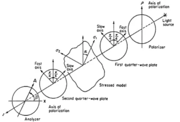
Fig. 1 Circular polariscope (dark-field setup) 이용한다. 등색선은 시편에서의 주응력 차이(differ-
ence of principal stress)에 의하여 나타나며, 등경선 은 주응력 방향(direction of principal stress)에 의하 여 나타난다. 일반적으로 광탄성 시편의 임의의 점에서 응력을 측정하기 위해서는 등색선과 등경 선에 타디 보정법(Tardy compensation method)과 같 은 방법을 이용해야 하며, 전체 응력장을 분석하 기 위해서는 각 점에 대하여 개별적으로 보정하여 측정하여야 하기 때문에 시간이 많이 소요되고 불 편하다는 단점이 있다[5-13].
본 연구에서는 이러한 수정측정에 의한 보정법 의 단점을 극복할 수 있는 4-버켓 위상이동법 (4-bucket phase shifting method)[14]을 이용하여 마름모 평판(rhombus plate)에서의 응력 분포를 해석하고자 한다. 원형편광기를 이용하여 압축하 중을 받는 마름모 평판의 중간 수평선상에서의 응력 분포를 광탄성 실험에 의하여 측정하며, 측 정된 값을 유한요소 상용 프로그램인 ANSYS에 의하여 분석 결과와 비교하여 유효성을 입증하고 자 한다.
2. 실험 광탄성 위상이동법 및 실험
2.1. 광탄성 위상이동 이론
광탄성에서 등색선은 Fig. 1과 같이 편광판 (polarizer), 두 개의 4분파판(quarter wave plate), 그리고 검광판(analyzer)으로 구성된 원형편광기 (circular polariscope)로부터 얻을 수 있다. 응력- 광법칙(stress-optic law)로부터 주응력 차이는 등 색프린지 차수와 다음 관계를 갖는다[2,3].
(1)
위의 식(1)에 나타낸 각각의 기호는 다음을 의미 한다.
: 최대 및 최소 주응력 차이
: 등색프린지 차수 : 광탄성 재료상수(material fringe constant)
: 시편 두께
한편으로, 원형편광기의 암시야배열(dark-field setup)에서 검광판을 임의의 각도 로 회전시켰
을 때 광강도(light intensity)
는 다음의 식(2)와 같다[2].
coscos cossinsin (2)위의 식에서 는 검광판 회전 각도, 는 시편의 등경각, 그리고 는 주응력 차이와 관계되는 시 편에서의 위상지연(relative retardation)을 의미한다.
검광판 회전각 에 대하여 최대 또는 최소 광 강도가 되기 위한 와 값은 다음 식과 같이 계산한다.
sinsinsin (3)
cos sin cossincos (4)
위의 식(3)과 (4)를 동시에 만족하는 와 값은 최소 광강도가 되며 아래 값들과 같은 조건에서 성립된다.
± ⋯ (5)
식(2)에서 광강도
이 되기 위해서는 주응력 방향중 한 축이 편광판의 축과 평행이 되어야 한 다. 즉, ⋯ 이 되어야 한다. 이 경 우, 프린지 차수는 다음과 같다.
±
(6)
위의 식(6)은 타디 보정법의 기본원리이다.
Fig. 2 Geometry of test specimen
Fig. 3 Isochromatic fringes in the dark field polari- scope set-up
Fig. 4 Distribution of light intensity along the hori- zontal line shown in Fig. 3
식(2)로부터 위상이동법에 관한 식을 구할 수 있다. 식(2)에서 배경잡음(back ground noise)
를 고려하고 로 대체시킨 후, 식(2)를 일반적 인 광강도에 관한 일반식으로 변형하여 나타내면 다음 식과 같이 쓸 수 있다.
cos (7)식(7)에서
는 프린지의 광강도를 의미한다. 는 위상차(phase difference)이며, 등색선 프린지 차수 를 구하기 위해 를 0에서 사이 의 값을 택할 수 있다. 원형편광기의 암시야배열 로부터 위상차를 로 변화시 켜가며 이에 해당되는 광강도로부터 다음의 4-버 켓 위상이동법(4-bucket phase shiting method)에 관한 식(8)을 얻을 수 있다[14].
tan
(8)식(8)로부터 에 관한 전체적인 위상도 (whole-field phase map)를 생성할 수 있다. 그러나 식(3)의 arc tangent 함수는 에서 범위 이 내이므로 위상점프(phase jump)가 나타난다. 이를 펼치면 에 관한 위상도(unwrapped phase map)을 얻을 수 있다.
2.2. 광탄성 실험 및 영상처리
프린지 위상이동법의 유효성을 입증하기 위하 여 Fig. 2와 같이 한 변의 길이가 a = 25.4 mm이 고 두께가 t = 5.8 mm인 우레탄 고무의 일종인 photoflex 재료[15]로 가공된 마름모 평판을 원형 편광기 4분파판 사이에 설치된 하중장치(loading frame)에 위치시킨 후, 약 P = 3.32N의 하중을 가 하였다. Photoflex재질의 영탄성계수는 E = 3.1N/
mm2, 그리고 광탄성프린지 상수는 0.16N /mm2/fringe/mm이다[15].
Fig. 3은 원형편광기의 암시야 배열에 설치된 시편에 하중이 가해진 상태에서 등색프린지 패턴 을 나타낸다. Fig. 4는 Fig. 3에 표시된 가로방향 의 수평선상에서 광강도이다. Fig. 4에서 표시된 바와 같이 최대 광강도는 50~60 사이에, 그리고 최소 광강도는 10~20 사이에 분포되어 있다. 이
(a)
(b)
(c)
(d)
Fig. 5 Fringe shifted patterns by rotating analyzer (a) 0 radian (b) π/4 radians (c) π/2 radians (d) 3π/4 radians
Fig. 6 Isochromatic fringe phase map obtained by rotating analyzer 0 radian, π/4 radians, π/2 radians and 3π/4 radians
Fig. 7 Light intensities of fringe phase map along the horizontal line which passes the central point
러한 이유로 하나의 프린지 영상으로부터 육안으 로 프린지 차수를 측정하기 위해서는 최대 및 최 소 광강도 지점을 정확히 측정해야 하는 어려운 점이 있다.
Fig. 5는 원형편광기에서 검광판을 각각 0, π/4, π/2, 3π/4 라디안 회전시켰을 때 나타난 프린지 영상이다. Fig. 6은 Fig. 5의 4개 영상을 식(8)에 적용하여 계산된 등색위상도(isochromatic phase map)이다. Fig. 7은 Fig. 6의 중앙 수평선상에서 광강도 분포를 나타낸다. Fig. 7에서 보인바와 같 이 중앙을 기준으로 양측에서 위상점프(phase jump)가 발생되었다.
Fig. 7에서 위상점프를 없애기 위해 위상이동 에 의한 광강도를 펼치면 Fig. 8과 같이 Fig. 6의 수평선상에서 펼친 위상도(unwrapped phase map)
Fig. 8 Unwrapped isochromatic fringe phase map obtained from Fig. 7
Fig. 9 Distribution principal stress difference meas- ured by photoelastic experiment along the horizontal axis of the specimen
Fig. 10 ANSYS discretization of the rhombus plate model
Fig. 11 Distribution of stress components calculated by ANSYS
에 관한 광강도 분포를 얻을 수 있다. Fig. 8에서 수평축은 픽셀 거리(pixel distance), 그리고 수직 축은 광강도(light intensity)를 나타낸다.
광강도와 프린지 차수, 그리고 픽셀 거리와 실 제치수 사이의 환산계수(conversion factor)를 적용 하면 마름모 판 대각 수평선상에 분포된 등색프 린지 차수 분포를 얻을 수 있다. 등색프린지 차 수로부터 식(1)을 이용하면 주응력 차이를 얻을 수 있으며, Fig. 9와 같이 광탄성 실험에 의한 주 응력 차이 분포(distribution of principal stress dif- ference)를 구할 수 있다.
3. 유한요소 해석
광탄성 실험으로부터 측정된 마름모 시편의 수 평 대각선상에 분포된 주응력 차이의 유효성을 검토하기 위해 상용유한요소 프로그램 ANSYS
[16]를 이용하여 계산하였다. Fig. 10은 Fig. 2에 나타낸 치수 (a = 25.4 mm, t = 5.8 mm)와 같이 상하 지점에서 압축하중을 받는 마름모 평판 해 석을 위한 유한요소 모델을 나타낸다. 사용된 요 소 종류는 Type 1, PLANE 182이며 2601개의 요 소로 분할하여 해석하였다.
Fig. 11의 그래프는 Fig. 10의 중앙 대각 수평 선상에서 해석 결과로부터 얻은 응력성분 분포를 나타낸다. Fig. 11에서 보인바와 같이 중앙 대각 수평선상에서 방향의 응력성분(SY), 즉 가 최대값인 압축응력을 나타내고 있다. 또한 전단 응력성분(S), 즉 는 0에 가까운 아주 적은 값 으로 수평선으로 나타나 있다. 또한 방향의 방 향의 응력성분(SX), 즉 σx는 양(+)의 값으로 대략
값 크기의 1/3정도로 계산되었다. Fig. 11에 나
Fig. 12 Principal stress distribution of FEM analysis along the center horizontal line of the rhom- bus plate under compression
Fig. 13 Comparison of principal stress distribution ob- tained by photoelastic experiment and results calculated by FEM analysis
타낸 응력성분으로부터 마름모 평판 시편 중앙 대각선상에서 유한요소해석으로부터 얻은 주응력 차이( ) 분포는 Fig. 12와 같다.
수직방향으로 하중을 받는 마름모 평판의 주응 력 분포에 대해 위상이동법을 이용한 광탄성 실 험법에 의해 측정된 값과 유한요소법으로 계산한 결과를 비교하면 Fig. 13과 같다.
Fig. 13에서 보인 바와 같이 광탄성(photoelastic experiment) 측정값과 유한요소법(FEM-ANSYS) 계산 결과는 대체적으로 서로 잘 일치하였다. 특 히 마름모 평판이 수직방향으로 하중을 받을 경 우, 양끝 모서리 부분에서 광탄성법으로 측정된 주응력 차이의 분포는 Fig. 13에서 보인 바와 같 이 사용된 유한요소 해석 결과보다 정밀한 분포
를 얻을 수 있었다. 양끝 모서리에 대해 유한요 소법으로 정밀한 결과를 얻기 위해서는 좀 더 조 밀한 요소로 분할하여야 함을 시사하였다.
4. 결 론
광탄성법은 실험역학에서 응력 분포를 측정하 기 위하여 널리 활용되고 있다. 그러나 수작업으 로 측정하기 위해서는 측정하고자 하는 한 점, 한 점에 대해 보정법을 사용해야하므로 숙련을 필요로 하며 많은 시간이 소요된다.
본 논문에서는 기존의 광탄성법에 이용되는 수 작업에 의한 보정법의 단점을 극복할 수 있는 4-버켓 위상이동법을 이용하여 압축하중을 받는 마름모 평판에서의 응력 분포를 분석하였다. 위 상이동법을 적용한 광탄성실험으로부터 측정된 주응력 분포 차이는 유한요소법에 의하여 계산된 결과와 잘 일치함을 확인하였다. 또한 광탄성 위 상이동실험법은 시편의 모든 픽셀에 대해 CCD 카메라의 해상도에 따라 측정이 가능하므로 정밀 한 기계/구조물의 설계 및 해석에 적용이 가능할 것으로 사료된다.
후 기
이 논문은 2013년도 정부(교육과학기술부)의 재원으로 한국연구재단 기초연구사업 지원을 받 아 수행된 것임 (No. 2013070058).
참고문헌
[1] T. H. Baek, M. S. Kim and L. Chen, "Com- parison of full-field atresses around an inclined crack tip by using fringe data of finite element method with photoelastic experiment," Journal of the Korean Society for Nondestructive Test- ing, Vol. 29, No. 6, pp. 557-562 (2009) [2] J. W. Dally and W. F. Riley, "Experimental
Stress Analysis," 3rd Ed., McGraw-Hill, Inc.
(1991)
[3] C. P. Burger, "Chapter 5 Photoelasticity in Handbook on Experimental Mechanics," 2nd Ed., Edited by A. S. Kobayashi, Society for Experi-
mental Mechanics, Inc., Bethel, Connecticut, pp. 165-266 (1993)
[4] G. L. Cloud, "Optical Methods of Engineering Analysis," Cambridge University Press (1995) [5] T. H. Baek, M. S. Kim and S. H. Cho,
"Measurement of isochromatic fringe distri- bution of a TV glass panel by use of photo- elastic 4-step phase shifting method", Journal of the Korean Society for Nondestructive Testing, Vol. 25, No. 1, pp. 1-8 (2005) [6] T. H. Baek, M. S. Kim, Y. Morimoto and M.
Fujigaki, "Separation of isochromatics and isoclinics from photoelastic fringes in a circular disk by phase measuring technique,"
KSME International Journal, Vol. 16, No. 2, pp. 1207-1213 (2002)
[7] T. H. Baek and M. S. Kim, "Computer Simu- lation of Photoelastic Fringe Patterns for Stress Analysis," Systems Modeling and Simulation:
Theory and Applications, Lecture Notes in Computer Science, Issue Vol. 3398, pp. 214- 221 (2005)
[8] T. H. Baek, "Photoelastic stress analysis by use of hybrid technique and fringe phase shifting method," Journal of Experimental Mechanics, Vol. 21, No. 1, pp. 87-95 (2006) [9] L. Chen and T. H. Baek, "Accurate deter-
mination of stress intensity factor of a central crack by digital photoelasticity," Modern Phys-
ics Letters B, Vol. 22, No. 11, pp. 863-868 (2008)
[10] T. H. Baek, L. Chen and D. P. Hong, "Hybrid determination of mixed-mode stress intensity factors on discontinuous finite-width plate by finite element and photoelasticity," Journal of Mechanical Science and Technology, Vol. 25, No. 10, pp. 2535-2543 (2011)
[11] T. H. Baek and M. S. Kim, "Measurement of stress intensity factors of inclined crack in a tensile plate by using hybrid photoelastic tech- nique combined with FEA data," International Journal of Green Engineering and Management, Vol. 2, No. 1, pp. 1-9 (2013)
[12] T. H. Baek, "Development image processing technique for photoelastic isochromatic fringe sharpening," Journal of the Korean Precision Engineering, Vol. 10, No. 3, pp. 220-230 (1993) [13] T. H. Baek and J. C. Lee, "Development of
image processing technique for photoelastic fringe analysis," Trans. of KSME, Vol. 18, No. 10, pp. 2577-2584 (1994)
[14] A. Asundi, "Phase shifting in photoelasticity,"
Experimental Techniques, Vol. 7, No. 1, pp.
19-23 (1993)
[15] Sharples Stress Engineers Ltd. Unit 29, Old Mill Industrial Est., School Lane, Bamber Bridge, Preston, Lancs, U. K. PR5 6SY
[16] ANSYS 14, www.ansys.com, ANSYS, Inc.