DETORQUE FORCE OF TiN-COATED ABUTMENT SCREW WITH VARIOUS COATING THICKNESS AFTER REPEATED CLOSING AND OPENING
Han-Su Kim, D.D.S., M.S.D., Hee-Jung Kim, D.D.S., M.S.D., Ph.D., Chae-Heon Chung, D.D.S., M.S.D., Ph.D.
Department of Prosthodontics, College of Dentistry, Chosun University
Statement of problem. When TiN coating is applied to the abutment screw, occurrence of greater preload and prevention of the screw loosening could be expected due to decrease of frictional resistance. However, the proper thickness of TiN coating on abutment screw has not been yet reported.
Purpose.The purpose of this study is to find out the appropriate TiN coating thickness by evaluating the detorque force and the surface change of titanium abutment screw with vari- ous TiN coating thickness.
Material and methods.
1. Material
Thirty five non-coated abutment screws were prepared for TiN coating. TiN coatings were prepared by Arc ion plating method. Depending on the coating deposition time(CDT), experimental groups were divided into 6 groups(CDT 30min, 60min, 90min, 120min, 150min, 180min) and those of 1 group was not coated as a control group. Each group was made up of 5 abutment screws.
2. Methods
FE-SEM(Field Emission Scanning Electron Microscoper) and EDX(Energy Dispersive X-ray Spectroscopy) were used to observe the surface of the abutment screw. Electric scales was used to measure the weight of the abutment screw after the repeated closing and opening of 10 tri- als. Detorque force was measured with digital torque gauge, at each trial.
Results.
1. As the coating deposition time increased, the surface became more consistent and smooth.
2. As for the abutment screws that were TiN coated for more than 60 minutes, no surface change was found after the repeated closing and opening.
3. The TiN coated abutment screws showed less weight change than the non-coated abutment screws.
4. The TiN coated abutment screws showed higher mean detorque force than the non- coated abutment screws.
5. The abutment screw coated for 60 minutes showed the highest mean detorque force.
J Korean Acad Prosthodont : Volume 45, Number 6, 2007
※ This study was supported by research funds from Chosun University, 2006.
R
ecently, the use of osseointegrated implants has become popular in single tooth restoration, and partially edentulous and fully edentulous restora- tion. Regardless of the type of performed restora- tion, in most cases, a screw connection is used between the abutment and the implant. However, implant abutment screw loosening has remained a problem in restorative practices.1,2Abutment screw loosening was reported in large number of studies and ranged from 2% to 45% of the abut- ment.3-6The screw loosening does not occur when the clamping force of the screw exceeds the joint separating forces acting on the assembly.7-12 Joint separating forces may exceed clamping forces when implant assemblies are subject to non-axi- al loading because of implant position or angu- lation, or excessive occlusal forces.13Cantilever designs may amplify forces on screw joints due to the lever effect and should, when possible, be avoided.14Preload is the term that describes the tension gen- erated in the screw upon tightening and is a direct determinant of clamping force. As the abutment screw is torqued down, preload is generated within the screw, placing the abut- ment/implant assembly under compression.15,16The strength of the preload is a combination of the fric- tional forces in the mating threads and screw head, the metallurgical properties of the screw, and the applied closing torque.16Micromovement, component surface wear, and embedment relax-
ation during functional loading may gradually erode the preload and cause progressive slip- page and screw joint failure.16,17 When torque is applied to a new screw, about 90% of the input torque is used to overcome friction and only 10% to induce preload.18For this reason, a few man- ufactures altered the surface of abutment screws to reduce the friction coefficient and obtain a higher preload.19,20The most well- known abutment screws are Gold-Tite of 3i(3i, Florida, USA) and TorqTite of Steri-Oss(Nobel Biocare, Go¨teborg, Sweden) and WCC of Osstem(Osstem, Busan, Korea). Martin et al reported that Gold-Tite and TorqTite abutment screws with enhanced surfaces helped in reducing the friction coefficient and gen- erated greater rotational angles and preload val- ues than conventional screws.2Drago reported that the use of Gold-Tite square abutment screws, torqued to 32Ncm, maintained a stable abut- ment/implant connection that was successfully used in clinical practice for one year.21
Titanium nitride(TiN) coating is the most gen- eral and popular coating method and used to improve the properties of metallic surface for industrial purposes. This coating layer of 2-3μm thickness renders the surface scratch-proof and is considered to be clinically stable.22TiN is used as a hard coating for metal cutting tools like drills and burs, and forming tools such as dies and punch- es because it has high hardness, low friction coefficient and good resistance to adhesive wear.
Additionally, it has a golden appearance and is use- Conclusion. The coating layer of proper thickness is demanded to obtain consistent and smooth coating surface, resistance to wear, and increased detorque force of the abutment screw. In con- clusion, the coating deposition time of 60 minutes indicated improved mechanical property, when TiN coating was conducted on titanium abutment screw.
Key Words
Detorque force, Abutment screw, TiN
ful for ornamental purposes. TiN coating has been applied to clinical dentistry since early times. Clinical trials in which coated crown, par- tial fixed denture and removable prostheses made from casting dental alloy with TiN had been performed by several dentists.22Kim et al reported that TiN coating of abutment screw helped to reduce the risk of screw loosening and improved the stability of screw joint.23 When TiN coating was applied to the abutment screw, frictional resistance would decrease, and as a result, a greater preload and prevention of the screw loosening effect could be expected. However, the proper thickness of TiN coating on abut- ment screw has not been reported yet.
The purpose of this study is to find the appro- priate TiN coating thickness by evaluating the detorque force and surface change of titanium abut- ment screw with various TiN coating thickness.
MATERIAL AND METHODS 1. Material
Thirty five non-coated GSII abutment screws (Osstem, Busan, Korea) were prepared for TiN coating. They were randomly selected and divid- ed into 7 groups. Depending on the coating deposition time(CDT), experimental groups were
divided into 6 groups: group A(CDT 30min), group B(CDT 60min), group C(CDT 90min), group D(CDT 120min), group E(CDT 150min), group F(CDT 180min). TiN was respectively coated on the specimens of 6 groups, and those of 1 group(group G) was not coated as a control group. Each group was made up of 5 abutment screws(Table Ⅰ, Fig. 1).
2. Methods
1) TiN coating using Arc ion plating
TiN coatings were prepared by Arc ion plating method. To control the coating thickness, each group had the variation of coating deposition time, such as 30, 60, 90, 120, 150, and 180 minutes.
2) Mounting of implant fixtures
The implant fixtures used in this study were GSII of internal conical joint design (diameter 4mm and length 13mm; Osstem, Busan, Korea). Abutments used GS Transfer Abutment of hex standard design(diameter 5mm and gingival height 3mm and abutment height 5.5mm; Osstem, Busan, Korea). Thirty five pairs of implant fixtures and abutments were respectively selected. A specimen was composed of a assembly of a fixture, an abutment and an abutment screw. Each fixture was mounted in liquid unsaturated polyester. After the
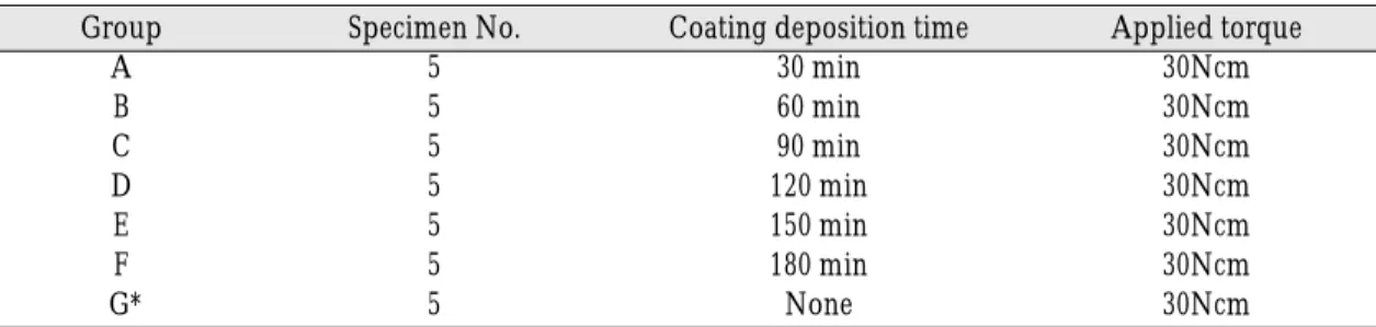
Table I. Classification of groups
Group Specimen No. Coating deposition time Applied torque
A 5 30 min 30Ncm
B 5 60 min 30Ncm
C 5 90 min 30Ncm
D 5 120 min 30Ncm
E 5 150 min 30Ncm
F 5 180 min 30Ncm
G* 5 None 30Ncm
* : Control group
mounting media was completely hardened, the abutment was connected to each fixture(Fig. 2).
3) Surface investigation of the abutment screw by FE-SEM and EDX
FE-SEM(Field Emission Scanning Electron Microscoper) was used to observe changes of surfaces of the abutment screws after the repeat- ed closing and opening of 10 trials. The surface of each abutment screw was observed at 100 mag- nifications, and then screw crest, valley, and slope were observed at higher magnifications:
1,000, 10,000, 100,000 and 500,000 magnification.
Before and after the repeated closing and open- ing, qualitative analysis was conducted by means of EDX(Energy Dispersive X-ray Spectroscopy).
4) Measurement of abutment screw weight In order to compare the wear resistance of var- ious TiN coating thickness on a abutment screw, the weight of the abutment screw was measured by electric scales(GENIUS ME, Sartorius, Germany) before and after the closing and opening of 10 tri- als.
5) Measurement of detorque force
The implant mounted fixture blocks were fixed in a specially devised specimen-holding apparatus before the repeated closing and opening. Each abut-
ment was secured to a implant fixture by abutment screw with recommended torque value(30Ncm) using a finger screw driver(Osstem, Busan, Korea) and a torque wrench(Osstem, Busan, Korea).
The finger screw driver was used to fix the abut- ment screw till thread mating components were slightly contacted. The torque wrench was used to tighten the screw to 30Ncm. It was used to insure that an accurate and reproducible force was applied to each abutment screw. The abutment screws were repeatedly tightened and removed for 10 trials. The number of trials included several try-in of abutment screw up to final setting.
Sample with abutment screw tightened was fixed in the customized jig for the measurement of detorque force. The detorque force was mea- sured with digital torque gauge(Mark-10 Corp., New York, U.S.A., Fig. 3).
3. Statistical analysis
SPSS statistical software for Windows(SPSS Inc., Chicago, U.S.A.) was used for statistical analysis. One-way ANOVA(Tukey test; level of significance, P<0.05) and validity test of Microsoft Excel were used for the comparison of the mean detorque forces and the tendency of detorque force change between the coated groups and the non-coated group.
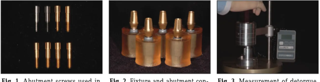
Fig. 1.Abutment screws used in this study.
Fig. 2.Fixture and abutment con- nection.
Fig. 3.Measurement of detorque force.
RESULTS
1. Surface investigation
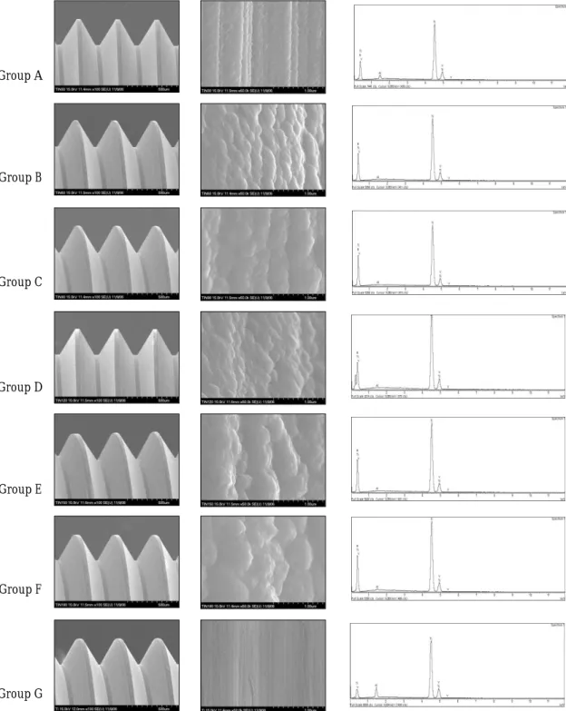
1) Before the repeated closing and opening According to the observation of the surface at the magnifications of 100 and 500,000, the non-coat- ed surfaces of control group(group G) showed a somewhat rough surface, while TiN particles adhered to the surface of the coated groups. As the coating thickness increased, the size of the adhered TiN particles grew bigger at the same magnifi- cation(Fig. 4). As a result of qualitative analysis of coating surface by using EDX, Ti, Al, and V were detected in the non-coated control group(group G), which was verified as Ti-6Al-4V alloy. In the experimental group, other than Ti, Al, and V, TiN was additionally detected. As the coating thick- ness increased, the EDX qualitative analysis showed greater portion of TiN ingredient than Ti, Al, and V ingredient(Fig. 4).
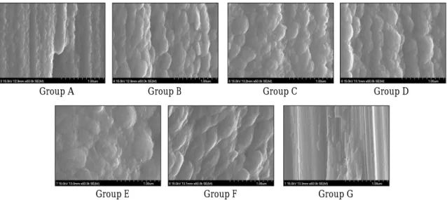
2) After the repeated closing and opening Compared with the surface investigation before the repeated closing and opening, the surface change on all groups was not observed in low mag- nification FE-SEM. However the high-powered FE- SEM analysis of Group A and Group G showed noticeable changes in screw threads after the test. The separation of coated TiN was detected in abutment screws of Group A, and Group G turned out to show wear surface and scratches. On the other hand, the surface change of other groups was not detected by the high-powered FE- SEM(Fig. 5). According to the qualitative analy- sis of coating surface using EDX, the surface ingredient did not show any difference com- pared with the analyzed before the repeated closing and opening.
2. Measurement of the abutment screw weight
According to the measurement of the abut- ment screw weight before and after the repeated closing and opening, Group G represented the most remarkable weight change, and Group A rep- resented the most remarkable weight change among TiN coated groups(Table II).
In comparison with other groups, Group G, showed a statistically significant difference(P<0.05, One-way ANOVA).
1) Statistical significances were tested by one-way of variances among groups
2) The same letters indicate significant difference between groups based on Tukey test 3. Measurement of detorque force
Table III shows the mean detorque forces of each trial. Group B had a higher mean detorque force than other groups. The TiN coated groups showed higher detorque force than group G(Non-coated).
All groups had a increasing tendency of detorque force as the closing and opening were repeated to the 3rd or the 4th trial. Furthermore, in the repeated trials after the 3rd or the 4th trial, the detorque forces showed a decreasing tendency.
In the 3rd or the 4th trial, all groups had maximal mean detorque force(Fig. 6). There was a statis- tically significant difference between Group B and Group G(P<0.05, One-way ANOVA). In the terms of maximal value, minimal value, and all tri- al detorque forces, Group B was higher than Group G. After the 4th trial, although Group B and Group G revealed declining tendency of mean detorque forces, Group G showed a steeper declining slope compared with Group B. In coat- ed groups, such as Group A, B, C, D, E, and F, despite the fact that every absolute mean detorque force was different, the tendency of detorque
Group A
Group B
Group C
Group D
Group E
Group F
Group G
Fig. 4.FE-SEM micrographs & EDX showing the coating surface and the ingredient of each group before the repeat- ed closing and opening (Left : ×100, Middle : ×500,000, Right: EDX).
Group A Group B Group C Group D
Group E Group F Group G
Fig. 5.FE-SEM micrographs showing coating surface of each group after the repeated closing and opening(×500,000).
Table II. The weight difference of the abutment screw between before and after the repeat- ed closing and opening
Group Mean weight difference(g) S2) P-value1)
A 0.000020±0.000016 f
B 0.000012±0.000025 e
C 0.000004±0.000006 b
D 0.000012±0.000022 d <0.05
E 0.000000±0.000010 a
F 0.000008±0.000015 c
G 0.000076±0.000011 a,b,c,d,e,f
1) Statistical significances were tested by one-way of variances among groups 2) The same letters indicate significant difference between groups based on Tukey test
Table III. Mean detorque force of each group
Group Mean detorque force(Ncm) S2) P-value1)
A 26.06±0.51 c,d
B 27.51±0.52
C 26.61±0.44 d
D 25.66±0.44 c <0.05
E 25.19±0.45 b,c
F 24.63±0.57 a,b
G 24.01±0.89 a
1) Statistical significances were tested by one-way of variances among groups
2) The same letters indicate non-significant difference between groups based on Tukey test
force transition was similar. There was a statistically non-significant difference between Group F and Group G(P<0.05, One-way ANOVA). Although the maximal detorque force of Group F was almost the same as Group G, the general ten- dency of detorque force change was different.
Additionally, the mean detorque forces between Group F and Group G, except for the 4th trial, showed considerable large differences.
1) Statistical significances were tested by one-way of variances among groups
2) The same letters indicate non-significant dif- ference between groups based on Tukey test DISCUSSION
The prevalent method to reduce the screw loosening is known as the application of dry lubricant coating on abutment screw.24The pur- pose of the lubricant is to reduce the frictional coef- ficient and obtain a higher preload. The need for coating with lubricant has been introduced long ago. The friction coefficient during the surface con- tact between titaniums gradually increases, as the tightening and loosening are repeatedly per- formed. Such an increase of the frictional coefficient effects the galling and seizing tendency of the tita-
nium. The beneficial properties of TiN film are low friction coefficient, high hardness and good wear resistance. Considering these properties of TiN coat- ing, TiN coating can be an alternative coating method; Koo et al applied TiN coating to abutment screws and examined those surface characteris- tics. As a result, abutment screws revealed salient improvement of mechanical properties.25Also, Kim et al reported that the titanium abutment screw coated with TiN scored a higher mean detorque force than the titanium abutment screw.26 In addition, Lee et al applied TiN coating of various thickness to titanium alloy disks and examined on the mechanical property. In this study, Lee et al reported that CDT(coating deposition time) of 60 min and 180 min indicated coating thickness of 1.05㎛ and 2.10㎛ respectively, suggesting coating thickness greater than 2㎛ showed homogenous and smooth coating surface with high-quality mechanical property.27 However, we consider that the study of Lee et al has a limitation in application of clinical practice due to it’s study based on TiN coated disk, not a TiN coat- ed abutment screw. Therefore, the purpose of this study is to investigate the detorque force and the surface change of titanium abutment screw of various TiN coating thickness.
1. Coating surface investigation
According to the researchers including Mezger, TiN coating showed improvement of the properties on wear-resistance, corrosion-resistance, and surface hardness.22When clamping torque force was applied to a screw surface with micro-rough- ness such as pores or micro-cracks, the loading excelling the yield strength causes plastic defor- mation of the screw surface.
The mechanism of screw loosening is based on the fact that the surface is not completely smooth. Even a carefully machined implant sur- face is slightly rough when viewed with a micro- Fig. 6.Comparison of mean detorque force among
groups.
scope. Because of this micro-roughness, no two sur- faces are in complete contact with one another.
When the screw interface is subjected to the external loads, micromovements occur between the surfaces. Wear of the contact areas might be a results of these motions, thereby bringing the two surfaces close to each other.28The magnitude of set- tling depends on the initial surface roughness and surface hardness as well as the magnitude of the loading forces.19 Rough surface and large external loads increase the settling. When the total settling effect is greater than the elastic elongation of the screw, the screw becomes loose due to lack of contact forces to hold the screw.29 Sakaguchi et al, reported that 2-10% preload dis- appeared by the influence of settling effect.30
Based on the study of Sopwith suggesting that only 3-4 screw thread is enough to fix upper structure, the observation of screw surface was focused on the upper 3-4 screw thread in this study.31
According to the observation of the abutment screw surface before the repeated closing and opening by use of FE-SEM, while Group G(Non- coated) surfaces showed traces of manufacturing process, other coated groups showed relatively con- sistent and smooth surfaces. As the coating thick- ness increased, the size of the adhered TiN par- ticles grew bigger at the same magnification. As the coating thickness increased, the EDX qualitative analysis showed greater portion of TiN ingredi- ent than Ti, Al, and V ingredient. This fact indi- cated that the surface-attached TiN ingredients increased as the coating deposition time increased.
TiN proportion beyond certain thickness level was observed equally, due to the penetrating depth lim- itation of the incident beam from FE-SEM. When the surface of TiN coated abutment screw was observed after the repeated closing and opening, the abutment screws coated with TiN for more than 60 minutes did not show surface change, and the exfoliation of TiN coating was observed at
Group A. In comparison between before and after the repeated closing and opening, the difference of EDX value was not revealed. According to this result, it is considered that the repeated clos- ing and opening did not affect the ingredient composition change of the coating surface.
On the basis of this result, when abutment screw is coated with TiN for homogeneous and consistent coating surface and the decrease of plastic deformation of coating surface at the repeated closing and opening, the abutment screw is required to be coated with TiN for more than 60 minutes.
2. Measurement of abutment screw weight
The major factor causing the screw loosening can be low wear resistance of the coating material, which can also lead to the plastic deformation and the exfoliation of the coating film. Therefore, the coating material of abutment screw requires high wear resistance to minimize screw loosen- ing. Wear resistance was not directly measured on the abutment screw due to it’s small size and thread shape. Thus, this study evaluated the wear resistance by means of the changes of abut- ment screw weight at before and after the repeat- ed closing and opening.
As shown in Table II the reduction of weight at before and after the repeated closing and opening was remarkable in Group G. There was a statis- tically significant difference between all groups (P<0.05, One-way ANOVA). However, the weight difference was too small to appreciate. As for the comparison of the abutment screw among the groups, the TiN coated abutment screws showed less weight change than the non-coated abut- ment screws. Therefore, the abutment screw requires TiN coating for the decrease of abutment screw wear at the repeated closing and open- ing.
3. Measurement of detorque force
In all groups, the detorque force showed an increasing tendency until the 3rd or the 4th trial, and a declining tendency from the 3rd or the 4th trial to the 10th trial. The increasing tenden- cy through the 1st to the 3rd or the 4th trial is due to the gradual decrease of irregular surface between the fixture and the abutment screw by the settling effect. The decreasing tendency from the 3rd or the 4th to the 10th trial is due to the grad- ual increase of friction between the fixture and the abutment screw by mechanical wear. In the analysis of the tendency of the detorque force tran- sition, the settling effect and the mechanical wear were not independent phenomenons. The influence of settling effect was more remarkable up to the 3rd or the 4th trial, while the influ- ence of adhesive or mechanical wear was more remarkable from the 3rd or the 4th trial to the 10th trial. In TiN coated groups, Group B showed maximal detorque force and slight declining ten- dency of mean detorque force. In every trial, the detorque forces of Group B were higher than those of Group G. In addition, Group B had slighter declining tendency than Group G.
This result shows that TiN coated abutment screw has advantages over non-coated titanium abutment screw on every aspect.32The mechan- ical properties of the TiN coated abutment screw such as low friction coefficient and improved hardness are considered to contribute in the increase of the detorque force and the decrease of the loosening of the abutment screw. When applied on the abutment screw, the Group B TiN coating thickness indicated the highest mean detorque force.
CONCLUSION
In this study, for the determination of proper TiN
coating thickness, we used implant system hav- ing internal conical type. Surface change and detorque force of abutment screw with various TiN thickness was measured for evaluating proper coat- ing thickness after the repeated opening and closing. According to the result of this study, we obtained the following conclusions.
1. As the coating deposition time increased, the surface became more consistent and smooth.
2. In abutment screws that were TiN coated for more than 60 minutes, no surface change was found after the repeated closing and opening.
3. The TiN coated abutment screws showed less weight change than the non-coated abut- ment screws.
4. The TiN coated abutment screws showed higher mean detorque force than the non-coat- ed abutment screws.
5. The abutment screw coated for 60 minutes showed the highest mean detorque force.
The coating layer of proper thickness is demand- ed to obtain consistent and smooth coating sur- face, resistance to wear, and increased detorque force of the abutment screw. In conclusion, the coat- ing deposition time of 60 minutes (Group B) indicated improved mechanical property, when TiN coating was conducted on the titanium abut- ment screw. Therefore, the TiN coating can be one of the resolution for the loosening of the abutment screw.
REFERENCE
1. Goodacre CJ, Kan JKY, Rungcharassaeng K.
Clinical complications of osseointegrated im- plants. J Prosthet Dent 1999;81:537-552.
2. Martin WC, Woody RD, Miller BH, Miller AW.
Implant abutment screw rotations and preloads for four different screw materials and surfaces. J Prosthet Dent 2001;86:24-32.
3. Andersson B, Odman P, Lindvall AM. Single- tooth restorations supported by osseointegrated im-
plants : Results and experiences from a prospective study after 2 to 3 years. Int J Oral Maxillofac Implants 1995;10:702-711.
4. Avivi-Arber L, Zarb GA. Clinical effectiveness of implant-supported single tooth replacement : the Toronto study. Int J Oral Maxillofac Implants 1996;11:311-321.
5. Kim NH, Chung CH. A study on the fit of the im- plant-abutment-screw interface. J Korean Acad Prosthodont 2003;41(4):503-518.
6. Jemt T, Petterson P. A 3-year follow-up study on single implant treatment. J Dent 1993;21:203-208.
7. Jemt T, Laney WR, Harris D. Osseointegrated im- plants for single tooth replacement: A 1-year report from a multicenter prospective study. Int J Oral Maxillofac Implants 1991;6:29-36.
8. Naert I, Quirynen M, van Steenberghe D. A six-year prosthodontic study of 509 consecutively inserted implants for the treatment of partial edentulism.
J Prosthet Dent 1992;67:236-245.
9. Goodacre CJ, Bernal G, Rungcharassaeng K.
Clinical complications with implants and implant prostheses. J Prosthet Dent 2003;90:121-132.
10. Wolfinger GJ. Implant prosthodontic and restora- tive complications. Int J Oral Maxillofac Implants 2003;18:766-767.
11. Hebel KS, Gajjar RC. Cement-retained versus screw-retained implant restorations: Achieving optimal occlusion and esthetics in implant dentistry.
J Prosthet Dent 1997;77:28-35.
12. Mcglumphy EA, Mendel DA, Holloway JA. Implant screw mechanics. Dent Clin North Am 1998;42:
71-89.
13. Rangert B, Jemt T, Jorneus L. Forces and mo- ments of Branemark implants. Int J Oral Maxillofac Implants 1989;4:241-247.
14. Brosky ME, Korioth TW, Hodges J. The anterior can- tilever in the implant-supported screw-retained mandibular prosthesis. J Prosthet Dent 2003;89:
244-249.
15. Burguete RL, Johns RB, King T, Patterson EA.
Tightening characteristics for screwed joints in osseointegrated implants. J Prosthet Dent 1994;
71:592-599.
16. Haack JE, Sakaguchi RL, Sun T, Coffey JP.
Elongation and preload stress in dental implant abutment screws. J Oral Maxillofac Implants 1995;10:529-535.
17. Binon PP. The effect of implant/abutment hexag- onal misfit on screw joint stability. Int J Prosthodont 1996;9:149-160.
18. Motosh N. Development of design charts for bolts preloaded up to the plastic range. J Eng Ind 1976:
98:849-851.
19. Binon PP. Implants and components : Entering the
new millenium. Int J Oral Maxillofac Implants 2000;15:76-94.
20. Choi JU, Jeong CM, Jeon YC, Lim JS, Jeong HC, Eom TG. Influence of Tungsten Carbide/Carbon coat- ing on the preload of implant abutment screws. J Korean Acad Prosthodont 2006;44(2):229-242.
21. Drago CJ. A clinical study of the efficacy of Gold- Tite square abutment screws in cement-retained im- plant restorations. Int J Oral Maxillofac Implants 2003;18(2):273-278.
22. Mezger PR, Creugers NH. Titanium nitride coat- ings in clinical dentistry. J Dent 1992;20(6):342- 344.
23. Kim JN, Chung CH, Kim HJ. Surface change and fit of TiN-coated abutment screw after repeated clos- ing and opening. J Korean Acad Prosthodont 2007;45(1):119-130.
24. Burguete RL, Johns RB, King T. Tightening char- acteristics for screwed joints in osseointegrated den- tal implants. J Prosthet Dent 1994;71:592-599.
25. Koo CI, Chung CH, Choe HC. Effects of surface coating on the screw release of dental implant screw. J Korean Acad Prosthodont 2004;42(2):210- 225.
26. Kim HJ. Choe HC, Chung CH. Effect of TiN coat- ing of abutment screw on detorque force. J Korean Acad Prosthodont 2007;45(3):329-344.
27. Lee JY, Chung CH. Mechanical properties of TiN coated film with various coating thickness on ti- tanium alloy. J Korean Acad Prosthodont 2007 under review.
28. Winkler S, Ring K, Ring JD, Boberick KG. Implant screw mechanics and the settling effect : An overview. J Oral Implantol 2003;29:242-245.
29. Jorneus L, Jemt T, Carlsson L. Loads and designs of screw joints for single crowns supported by osseointegrated implants. Int J Oral Maxillofac Implants 1992;7:353-359.
30. Sakaguchi RL, Borgersen SE. Nonlinear contact analysis of preload in dental implant screws. Int J Oral Maxillofac Implants 1995;10:295-302.
31. Sopwith DG. The distribution of load in screw threads. Proc Inst Mech Eng 1948;159:373-383.
32. Weiss EI, Kozak D, Gross MD. Effect of repeated closure on opening torque values in seven abutment- implant systems. J Prosthet Dent 2000;84(2):194-199.
Reprint request to:
CHAE-HEONCHUNG, D.D.S., M.S.D., PH.D.
DEPARTMENT OFPROSTHODONTICS,COLLEGE OFDENTISTRY, CHOSUNUNIVERSITY,
421, SEOSUK-DONG,DONG-GU,GWANGJU,501-825, KOREA [email protected]