1. Introduction
Magnesium and magnesium alloys were introduced into the research community with a lot of promise due to its low density (1.77 g/cm3), good castability as well as work- ability, excellent damping capacity, fatigue resistance and abundant resources [1-4]. However, addition of Al and Zn as alloying elements to magnesium though increases the strength; reduces the corrosion resistance of the alloy significantly [5-10]. AZ31B Magnesium alloy has a mi- crostructure consisting of α (Mg) matrix and intermetallic β (Mg17Al12) phase, where the intermetallics (acts as cath- ode) form numerous micro-galvanic cells with α matrix (as anode) under corrosion environment affecting the pit- ting corrosion resistance. This is due to the fact that mag- nesium and its alloys have a negative open circuit potential (~ -1.5V vs NHE) in neutral pH environment facilitating anodic dissolution.
One of the ways to combat corrosion and its related problems is to employ coatings over the base alloy.
Chemical conversion coatings (anodizing, chromating, etc) are usually employed to improve the surface proper-
ties particularly corrosion, microhardness and thermo-op- tical properties for spacecraft components [11-16]. These coatings provide better adhesion for paints, lubricants and adhesives; to reduce contact resistance in electronic com- ponents, act as solid lubricant to prevent cold welding in space [17]. The black galvanic anodic coatings on mag- nesium alloys possesses high solar absorptance and infra- red emittance [14,15] which helps in reducing temperature variations across electronic components, typically experi- enced in space environment by tailoring the heat radiation characteristics as per the following equation [18].
(1)
where S is the solar constant (average value 1353 W/m2); Ap (cm2) is the projected surface area of the space- craft perpendicular to the sun rays; α the solar absorptance of the projected area; σ the Stefan–Boltzmann constant (5.67 × 10⁻¹² W/cm2 K4); A: the total surface area of the spacecraft in m2; ε the infrared emittance of the exposed surface; and T is the absolute temperature of the spacecraft.
However, the as-deposited black anodic coatings are very soft and harden after drying with the presence of micro-pores as reported in literature [19]. These mi-
Corrosion Resistance and Thermo-optical Properties of Lithium Polysilicate Spray Coated Anodized AZ31B Magnesium Alloy for Space Applications
Rahul Ghosh†, Hari K. Thota, and R. Uma Rani
Thermal Systems Group, U R Rao Satellite Centre, Indian Space Research Organization, Bangalore- 560017, India (Received September 23, 2019; Revised October 29, 2019; Accepted October 30, 2019)
A thin spray coating of inorganic black lithium polysilicate (IBLP) on black anodized AZ31B magnesium alloy was fabricated for better corrosion resistance and thermo-optical properties for thermal control of spacecraft components. The morphology of the specimens with and without IBLP-based spray coating was characterized by SEM-EDS techniques. Impedance and potentiodynamic measurements on the specimens revealed better corrosion resistance for the specimen with a thin coating of lithium polysilicate. This was primarily due to the presence of lithium polysilicate inside the micro-cracks of the black anodized specimen, restricting the diffusion paths for corrosive media. Environmental tests, namely, humidity, thermal cycling, thermo vacuum performance, were used to evaluate the space-worthiness of the coating. The thermo-optical properties of the coating were measured before and after each environmental test to ascertain its stability. The specimen with an IBLP-based spray coating showed enhanced thermo-optical properties, greater than ~0.90. Hence, the proposed coating demonstrated better handling, better corrosion resistance, and space-worthiness during the pre-launch phase owing to its improved thermo-optical properties.
Keywords: Potentiodyamic polarization, Impedance spectroscopy, Magnesium alloy, Coatings, Lithium polysilicate
†Corresponding author: [email protected]
cro-pores may affect corrosion resistance as the spacecraft components are fabricated and stored for long time to meet recurring launch activities. In order to further tailor its surface properties, in this present study the black anodized (chromate conversion coated) components were followed by inorganic black lithium polysilicate (IBLP) based spray coating. Unlike organic coatings, inorganic lithium poly- silicate coatings are friendly to environment and resistant to ultraviolet exposure [20].
Therefore, this study is aimed at fabricating the compo- site coating with IBLP based spray coating and evaluate the corrosion resistance with respect to impedance spec- troscopy and potentiodynamic polarization. SEM-EDS analysis was employed to study surface morphology and chemical composition of the coatings. Also, to ascertain the space worthiness of the coating, thermo-optical proper- ties before and after the environmental tests (humidity, thermal cycling and thermo-vacuum tests) were studied in detail.
2. Experimental
2.1 Materials and methods
For the present study, AZ31B Magnesium Alloy was used in the form of rectangular specimen (50 mm × 50 mm) of 5 mm thickness, having nominal composition Mg-3Al-1Zn (wt%). The specimens were subjected to black anodizing (referred as BA) followed by two cross coats of inorganic lithium polysilicate spray coating having thickness less than 1 μm; this composite coating being referred as ISP-BA throughout the text. The detailed fol- lowing sequence of operations is carried out for the specimens. All reagents used were of laboratory grade, and de-mineralised water was used for the entire processing.
(1) Solvent cleaning ultrasonically with isopropyl alco- hol for 10 min. at 25 °C.
(2) Alkaline cleaning in a solution containing 50 g/L NaOH and 10 g/L, tri sodium orthophosphate for 10 min at 55 ± 5 °C, followed by water rinsing in di-mineralised water (DM).
(3) Acid cleaning in a solution containing 180 g/L chro-
mic acid, 40 g/L ferric nitrate, 4.5 g/L potassium fluoride for 3 - 4 min at 25 °C followed by water rinsing in DM water.
(4) Black Anodizing was obtained as per the reported procedure [21] in an electrolyte system consists of 25 g/L potassium dichromate and 25 g/L ammonium sulphate in stainless steel tank, at room temperature for 45 min.
Anode (sample) was connected to cathode (stainless steel tank) by suitable cable to facilitate the flow of galvanic current (0.8 - 2.4 mA/cm2). The tank containing the sol- ution was under continuous agitation and filtration and the pH was maintained at 5.8 ± 3. The pH was adjusted upward by adding dilute ammonium hydroxide and down- ward by adding dilute sulphuric acid.
(5) Heat treatment for 2 h at 70 °C in an oven under forced hot air circulation. Specimens referred as BA were taken at this stage for further characterization.
(6) To carry out inorganic lithium polysilicate spray coating the paint mixture was prepared by adding 100 mL of DM water with 100 mL IBLP paint. Subsequently, the paint mixture was sprayed in the form of two cross coats on the specimens using a Low Volume Medium Pressure (LVMP) Gravity fed air spray gun under 2 bar pressure.
IBLP is composed of water based lithium polysilicate as binder and carbon black as pigment. It is a self-cured coat- ing [20] and in this present study seven days was given for curing before using for actual applications. Specimens referred as ISP-BA were taken at this stage for further characterization.
2.2 Measurement techniques
The surface morphology of the coating has been inves- tigated by a scanning electron microscope (SEM). The morphological studies and the elemental analysis of the composite coating were carried out with a Carl Zeiss EVO-50 scanning electron microscope (SEM; Carl Zeiss, Oberkochen, Germany) with an EDS attachment.
The thickness of the black anodized film was measured using Fischer Isoscope thickness meter which works on the principle of eddy current, prior to application of paint mixture.
Environmental tests such as humidity, thermal cycling Table 1 Environmental test conditions
Test Test Conditions
Humidity 95% RH at 50 oC; 48 h
Thermal Cycling -45 oC to + 80 oC, 5 min dwell time; 1500 cycles Thermo Vacuum 10-5 torr, -45 oC to + 80 oC, 2 h dwell time; 10 cycles
and thermo-vacuum tests were carried out as per the de- tails shown in Table 1. Subsequently, the specimens (BA and ISP-BA) were evaluated visually under magnification (4X) for any degradation in physical appearance.
The optical properties, such as, solar absorptance and infrared emittance of the BA and ISP-BA specimens; were measured using a solar reflectometer version 50, model SSR-ER and an emissometer model RD1, respectively;
from Devices and Services Co. (USA): both before and after the environmental (humidity, thermal cycling and thermo-vacuum) tests. These instruments provide an aver- age value of solar absorptance (αs) and infrared emittance (εIR) digitally over the entire solar (240 - 2200 nm) and infrared regions (2.5 - 20 μm).
Corrosion resistance of the BA and ISP-BA specimens was evaluated through potentiodynamic polarization and impedance spectroscopy techniques using computer con- trolled using a frequency response analyser (Autolab PGSTAT 302N, Eco-chemie, The Netherlands) driven by Nova 1.4 software. Unstirred 3.5% NaCl solution prepared with distilled water that has been exposed freely to the atmosphere was used as corrosive medium. Tests were
carried out using a standard three-electrode setup with Pt as counter electrode, Ag/AgCl (saturated with KCl) as ref- erence electrode. Potentiodynamic polarization was car- ried out at a scan rate of 1 mVs-1 in the applied potential range of - 0.250 V to + 0.600 V with respect to OCP.
Impedance measurements were carried out on the BA and ISP-BA specimens in the frequency range of 50 kHz to 0.01 Hz with an amplitude of ± 10 mV.
3. Results and Discussion
3.1 Morphological studies
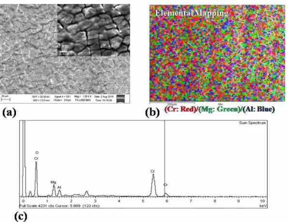
Fig. 1 shows the typical SEM morphology of the mud- cracked pattern of BA specimens after heat treatment;
probably due to shrinkage of the anodic film [14,15,19].
Fig. 1b shows the SEM-EDS spectrum of the anodic coating indicating presence of Mg, Cr, Al and O. The deposition of the coating takes place through controlled redox reaction between the alloy surface and Cr6+ in Cr2O72-
, where the alloy surface is oxidised by Cr6+ which in turn is reduced to Cr3+. Subsequently, a flow of galvanic current starts between the alloy surface (anode) and the Fig. 1 (a) Typical SEM morphology of BA specimen with higher magnification image (as an inset) , (b) elemental mapping of the specimen surface, (c) SEM-EDS spectrum showing presence of Mg, Cr, Al, O (not assigned any color in 1 (b)).
stainless steel tank (cathode) containing the anodizing solution, confirming the start of the anodizing process.
The anodized layer is a thin complex layer of chromium- metal gel comprising of compounds of Cr6+ and Cr3+ [16], which after hardening post heat treatment represents the morphology as indicated in Fig. 1.
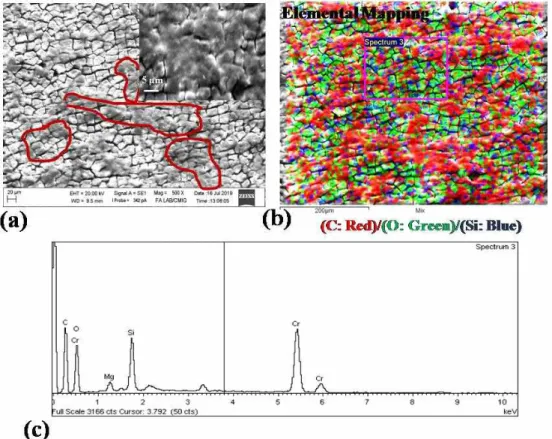
Fig. 2a represents the SEM micrograph of ISP-BA specimen, where dark patches (indicated in red color cir- cles) are seen evenly distributed throughout the anodized surface. One such area containing the dark patches is shown as a higher magnification image (refer inset (Fig.
2a). These dark patches are confirmed as C (refer Fig.
2b) which is the pigment in the paint mixture. One inter- esting observation from Fig. 2b is that the micro-cracks present in the as anodized (BA) specimen are filled with lithium polysilicate (sole binder in the paint mixture) as confirmed by the presence of Si (refer blue color in Fig.
2b) in EDS spectrum (refer Fig. 2c). However, lithium having a low x-ray yield being very light element cannot be detected through SEM-EDS [22]. Hence, it is believed that Si may be present in the form of lithium polysilicate inside the micro-cracks.
3.2 Corrosion studies
Fig. 3 and Fig. 4 represent the impedance data obtained for the base metal, BA and ISP-BA specimens after im- mersion for 0.5 h in 3.5% NaCl. The Nyquist plots shown in Fig. 3 demonstrated single semi-circle for all the samples. The intersections of the real axis in the Nyquist Fig. 2 (a) SEM morphology of ISP-BA specimen with higher magnification image (as an inset), (b) elemental mapping of the specimen surface, (c) SEM-EDS spectrum showing presence of C, Si and O.
Fig. 3 Nyquist plot for ISP-BA, BA and base alloy specimens.
plot is assigned as solution resistance (Rs) at higher fre- quencies, and charge transfer resistance (Rct) at lower frequencies. Hence the corrosion resistance of the coatings increases with increase in the diameter of the semi-circle, with higher Rct values. In Fig. 3, ISP-BA specimen shows the highest corrosion resistance (high Rct values) and base alloy shows the lowest corrosion resistance (lowest Rct
values-depicted as an inset in Fig. 3).
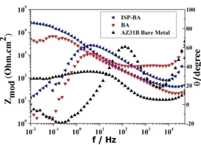
The Bode plots shown in Fig. 4 indicate that the im-
pedance values of the specimens as seen from the low frequency end of the spectrum are higher, intermediate and lowest for ISP-BA, BA and base alloy specimens, respectively. This is further substantiated by the Bode phase angle plot (Fig. 4) where base alloy specimen showed narrow peak and flattening of phase angle maxima for ISP-BA and BA specimens. The experimentally ob- served phase angle maxima for ISP-BA specimen were higher as compared to BA specimen.
The above Nyquist and Bode plots indicate that the (i) corrosion resistance of the ISP-BA specimen is the highest due to the fact that the micro-cracks noticed in as anodized BA specimen are fairly covered by lithium polysilicate present as binder in the paint mixture (refer Fig. 2), there- by restricting direct diffusion paths for corrosive media;
(ii) corrosion resistance of the BA specimen lies in the intermediate region due to the fact that the presence of micro-cracks in anodic coating of 6 μm gives less barrier protection from corrosive media; and (iii) the poor corro- sion resistance of the base alloy is due to fact that the natural oxide film on the magnesium alloy is susceptible to chloride containing environments [6-8] and does not offer barrier protection. The impedance results are further interpreted by fitting the EIS data with valid equivalent circuits. In this work, a single R-C element is proposed (shown as an inset in Fig. 3). The fitting results obtained from the impedance plots within the limits of experimental error (less than 5%) are summarized in Table 2. The equivalent circuit model consists of the solution resistance (Rs) connected in series with single time constant (CPE/Rct), where CPE is the capacitance of the passive film and Rct is the charge transfer resistance. An examina- tion of the Table 2 shows that the composite coating with inorganic lithium polysilicate (ISP-BA) exhibits higher Rct
values (22.83 kΩ.cm2) than BA (3.975 kΩ.cm2) and base alloy (0.182 kΩ.cm2). Correspondingly, the impedance values are 26.19 kΩ.cm2, 5.05 kΩ.cm2, and 0.09 kΩ.cm2 for ISP-BA, BA and base alloy respectively.
The potentiodynamic polarization plots obtained for ISP-BA, BA and base alloy in 3.5% NaCl are presented in Fig. 5. The electrochemical parameters such as corro- sion potential (Ecorr), corrosion current density (icorr) and Fig. 4 Typical Bode impedance plots obtained for the specimens;
Impedance vs. Frequency and Phase angle vs. Frequency.
Fig. 5 Potentiodynamic polarization curves for ISP-BA, BA and base alloy specimens.
Table 2 Fitting results obtained from EIS measurements
CPE (Fcm-2) Rct (kΩ.cm2) Rs (Ω.cm2) n
Base Alloy 9.52E-3 0.182 10.69 0.99
BA 5.79E-5 3.975 36.42 0.99
ISP-BA 3.73E-5 22.83 23.60 0.99
polarization resistance (Rp) obtained from the polarization plots are shown in Table 3. The corrosion current was obtained using the Stern-Geary equation [23].
(1)
where icorr is a corrosion current in μA/cm2; ba and bc
are the anodic and cathodic Tafel slopes, respectively, ex- pressed in V/decade; and Rp is the polarization resistance expressed in Ω.cm2. An examination of the polarization plots indicates that ISP-BA specimen exhibited lower icorr
(0.25 μA/cm2) than BA (3.34 μA/cm2) and base alloy (10.50 μA/cm2) specimens, indicating better corrosion resistance. Close observation of the polarization plots, re- vealed that the slope of the active region for the specimens are in the following order: ISP-BA > BA > base alloy (approaching zero). This can be attributed due to active dissolution at open circuit potential for base alloy; and effective barrier protection for ISP-BA specimen due to anodic coating as well as lithium polysilicate present in- side the micro-cracks, restricting entry of Cl- ions. The corrosion rate in millimetre per year (mm/year) was also evaluated using Tafel extrapolation method, based on Faraday's law [24,25] and tabulated in Table 3.
(2)
where icorr is the corrosion current density (μA/cm2), E.W is the equivalent weight in grams, and D is the den- sity of the metal (g/cm3). The above results evaluated from potentiodynamic polarization are in accordance with the impedance results (Table 2).
3.3 Environmental studies and thermo-optical properties The black anodized coating with lithium polysilicate spray coating (ISP-BA) was examined visually under magnification (4X) for any degradation in physical appear- ance before and after environmental tests. The coating was uniform without any physical defects.
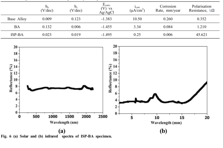
The solar and infrared spectra of ISP-BA specimen are represented in Fig. 6a and Fig. 6b, respectively. Both the spectra demonstrated reflectance values less than 10%
over the entire solar and infrared regions. One of the es- sential requirements for this type of coating to be used for thermal control applications is achieving lower re- flectance values, as depicted in the present study. The re- flectance values in the solar and infrared regions are in accordance with literature data on typical black coatings Table 3 Fitting results obtained from potentiodynamic polarization curves
ba
(V/dec)
bc
(V/dec)
Ecorr, (V) vs Ag/AgCl
icorr
(μA/cm2)
Corrosion Rate, mm/year
Polarisation Resistance, kΩ
Base Alloy 0.009 0.123 -1.383 10.50 0.260 0.352
BA 0.132 0.006 -1.455 3.34 0.084 1.210
ISP-BA 0.023 0.019 -1.495 0.25 0.006 45.621
(a) (b)
Fig. 6 (a) Solar and (b) infrared spectra of ISP-BA specimen.
with high absorptance and emittance values [13].
Considering the samples are opaque and do not allow transmittance, the solar absorptance (αs) of the samples will be inverse to reflectance.
Subsequently, the specimens were subjected to follow- ing tests to ascertain the space worthiness of the coating (refer Table 1).
Humidity test
This test was adopted to validate the resistance of the coating to humidity, since the spacecraft components are likely .to encounter higher humidity during the launch phase at coastal areas. This test was run in a thermostati- cally controlled humidity chamber for 96 h, where the relative humidity was maintained at 95 ± 5% at 323K.
Thermal Cycling
This test was adopted to examine the effect of extreme temperatures encountered during the mission lifetime due to direct solar load on one side and cold deep space on the other side. In this test, a total of 1500 cycles were adopted for the specimens; a cycle consists of lowering the temperature to 228K with a dwell time of 5 min and raising the temperature to 358K with a dwell time of 5 min.
Thermo-vacuum test
This test was adopted to examine the effect of thermal cycling under vacuum of 10-5 Torr (condition spacecraft encounters in outer space). In this test, a total of 10 cycles of hot and cold soaks were adopted for the specimens;
a cycle consists of lowering the temperature to 228K with a dwell time of 2 h and raising the temperature to 358K with a dwell time of 5 min.
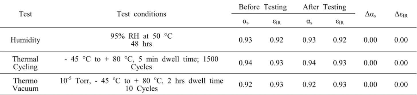
All the specimens after the above tests were examined under magnification (4X) and no degradation in physical appearance was noticed. Table 4 shows the changes in thermo-optical properties before and after environmental tests. The reported values in Table 4 are in accordance
with the spectra presented in Fig. 6.
4. Conclusions
(A) In this present study, spray coating of inorganic black lithium polysilicate (IBLP) on black anodized AZ31B (ISP-BA) Magnesium alloy effectively filled the micro-pores present in as black anodized coating (BA);
as evident from SEM-EDS analysis.
(B) Impedance and potentiodynamic measurements on the ISP-BA specimen revealed better corrosion resistance than BA specimen. This is primarily due to the presence of lithium polysilicate inside the micro-cracks of black anodized specimen, restricting diffusion paths for corro- sive media. The corrosion resistance as evaluated from these experiments was found in the following order:
ISP-BA>BA>Base alloy.
(C) Thermo-optical properties of the coating were measured before and after the environmental tests (humidity, thermal cycling and thermo-vacuum tests) to ascertain its stability. The specimen with IBLP based paint showed enhanced optical properties (αs and εIR), greater than 0.90.
(D) Hence, the proposed coating demonstrated better handling during pre-launch phase owing to its better corro- sion resistance and space worthiness owing to its better thermo-optical properties.
Acknowledgement
The authors express their sincere thanks to Director, URSC for permitting to publish the paper.
References
1. R. F. Decker, Adv. Mater. and Proc., 154, 31 (1998).
2. J. R. Thomas and L. A. Darryl, Adv. Mater. Proc., 145, 28 (1994).
3. F. H. Froes, D. Eliezer, and E. Aghion, J. Miner. Met.
Mater. Soc., 5, 30 (1998).
Table 4 Change in thermo-optical properties before and after environmental tests
Test Test conditions Before Testing After Testing
Δαs ΔεIR
αs εIR αs εIR
Humidity 95% RH at 50 °C
48 hrs 0.93 0.92 0.93 0.92 0.00 0.00
Thermal Cycling
- 45 °C to + 80 °C, 5 min dwell time; 1500
Cycles 0.94 0.93 0.94 0.93 0.00 0.00
Thermo Vacuum
10-5 Torr, - 45 oC to + 80 oC, 2 hrs dwell time
10 Cycles 0.92 0.93 0.92 0.93 0.00 0.00
4. E. F. Emley, Principle of Magnesium Technology, 1st ed., pp. 1 - 1034, Pergamon Press, London, UK (1966).
5. S. R. Agnew and J. F. Nie, Scr. Mater., 63, 671 (2010).
6. X. Chen, G. Li, J. Lian, and Q. Jiang, Appl. Surf. Sci., 255, 2322 (2008).
7. L. Li, Y. Cheng, H. Wang , and Z. Zhang, Trans.
Nonferrous Met. Soc. China, 18, 722 (2008).
8. N. Pebere, C. Riera, and F. Dabosi, Electrochim. Acta, 35, 555 (1990).
9. G. Baril and N. Pebere, Corros. Sci., 43, 471 (2001).
10. G. Baril, C. Blanc, M. Keddam, and N. Pebere, J. Electrochem.
Soc., 150, B488 (2003).
11. M. Dabala, K. Brunelli, E. Napolitani, and M. Magrine, Surf. Coat. Technol., 172, 227 (2003).
12. L. Bai, D. Li, M. Guo, and J. Xin, Material Sci. Forum, 546-549, 555 (2007).
13. A. K. Sharma, R. Umarani, H. Bhojaraj, and H. Narayanamurthy, J. Appl. Electrochem., 23, 500 (1993).
14. A. K. Sharma, R. Umarani, A. Malek, K. S. N. Acharya, M. Muddu, and S. Kumar, Met. Finish., 94, 16 (1996).
15. A. K. Sharma, J. Spacecr. Technol., 7, 49 (1997).
16. J. E. Gray and B. Luan, J. Alloy. Compd., 336, 88 (2002).
17. A. K. Sharma, Trans. SAEST, 30, 1 (1995).
18. B. N. Agarwal, Design of Geosynchronous Spacecrafts, p. 281, Printice-Hall, Englewood Cliffs, NJ (1986).
19. R. Uma Rani, V. Maria Shalini, Hari Krishna Thota, and A. K. Sharma, J. Coat. Technol. Res., 10, 707 (2013).
20. G. Parashar, M. Bajpayee, and P. K. Kamani, Surf. Coat.
Int. Pt. B-Coatings Transactions, 86, 209 (2003).
21. A. K. Sharma, R. Uma Rani, and K. Giri, Met. Finish., 95, 43 (1997).
22. J. Goldstein, D. E. Newbury, D. C. Joy, C. E. Lyman, P. Echlin, E. Lifshin, L. Sawyer, and J. R. Micheal, Scanning Electron Microscopy and X-ray Microanalysis, 3rd ed., pp. 1 - 689, Springer US, Boston (2003).
23. M. Stern and A. L.Geary, J. Electrochem. Soc., 104, 56 (1957).
24. D. A. Jones, Principles and Prevention of Corrosion, 2nd ed., pp. 1 - 572, Prentice-Hall, Upper Saddle River, NJ (1996).
25. K. H. Kim, S. H. Lee, N. D. Nam, and J. G. Kim, Corros.
Sci., 53, 3576 (2011).