J. Korean Soc. of Marine Engineering (JKOSME) ISSN 2234-8352 (Online)
http://dx.doi.org/10.5916/jkosme.2016.40.8.686 Original Paper
This is an Open Access article distributed under the terms of the Creative Commons Attribution Non-Commercial License (http://creativecommons.org/licenses/by-nc/3.0), which permits
† Corresponding Author (ORCID: http://orcid.org/0000-0002-1679-7961): Department of Refrigeration and Air-Conditioning Engineering, Pukyong National University, 365, Sinseon-ro, Nam-gu, Busan, 48547, Korea, E-mail: [email protected], Tel: 051-629-6182
H Vertical size of a plain-fin (mm)
Nu Nusselt number -
Ra Rayleigh number -
s Plain-fin offset (mm)
△T The temperature difference between a tube wall and ambient air (℃)
Ta Ambient air temperature (℃)
Tw Tube wall temperature (℃)
W Horizontal size of a plain-fin (mm)
Numerical analysis of a plain-fin type heat exchanger with two tubes in a crevice-type heat pipe
Eun-Pil Kim†
(Received July 19, 2016; Revised September 2, 2016;Accepted September 28, 2016)
Abstract: This paper employs numerical tools to obtain an optimal thermal design of a heat exchanger with plain-fins. This heat exchanger is located at the condensing section of a crevice-type heat pipe. The plain-fins in the heat exchanger are radi- cally mounted to two tubes in the condensing section. To obtain the optimal design parameters, a computational fluid dynamics technique is introduced and applied to different placement configurations in a system module. Owing to its effects on the heat pipe performance, the temperature difference between the tube surfaces and ambient air is investigated in detail. A greater heat dissipation rate occurs when the plain-fin offsets change from 2 to 3 mm. When this temperature difference is °C, the upper part of the plain-fins undergoes an accumulation of heat. At below 70 °C, the dissipation of heat is accepted. A rec- tangular plain-fin geometry with varying widths and heights does not have a significant impact on the heat dissipation through- out the overall system. In addition, the temperature distributions between different plain-fin pitches show an equal profile even with different fin pitches.
Keywords: Computational fluid dynamics, Crevice-type heat pipe, Heat exchanger, Plain-fin
Nomenclature
1. Introduction
Fins are widely used to enhance the heat transfer within the outside surface area of a surrounding solid medium. In addition, fins can be applied to improve the heat transfer coefficient in an outside tube containing a moving liquid medium. Different types of fins based on the tube arrangement and possible spacious offsets can be selected. In general, fins are coincident to the centroid of a tube in a radial direction. A plain-fin heat exchanger with a single tube is commonly used to transfer heat between a gas and liquid.
This type of heat exchanger is widely used in refrigeration,
air-cooling, and HVAC systems because a low heat transfer on the gas side can be largely increased through the attachment of fins on the outside surface of a tube.
Kundu and Das [1] investigated the optimum dimensions of the fins in a fin-tube heat exchanger, and suggested an optimal pitch length and fin thickness for a specified volume. Nemati and Samivand [2] presented a numerical study on obtaining the optimum efficiency of annular elliptical fins. They in- dicated that conventional methods, including an equivalent fin or sector method, do not achieve sufficient accuracy. They then suggested a simple correlation to improve the fin efficiency. Mon and Gross [3] presented the effects of fin spacing for tube bundles with different tube arrangements.
They found that the development of a boundary layer is highly dependent on the fin spacing to height ratio. Nuntaphan et al.
[4] presented the air-side performance in a cross-flow heat ex- changer with crimped spiral fins, and investigated the effects of the tube diameter, fin spacing, transverse tube pitch, and tube arrangements. Kundu and Das [5] suggested the effi- ciency of non-circular fins circumscribing circular tubes. They showed the results for square, hexagonal, and eccentric annular fins. Kundu et al. [6] investigated the thermal performance of rectangular plate fins circumscribing elliptic tubes. They used
an FEM method using quadratic serendipity elements, and sug- gested optimizing the fin geometry for a given fin surface.
The system used in a high-power vehicle LED package is composed of heat-generated LED sources and a passive cool- ing tool of a crevice-type heat pipe. To obtain a better passive cooling performance in a condensing section of a crevice-type heat pipe (CVCHP), Kim et al. [7] used an experimental method in which a CVCHP with a falling film type geometry design in a vapor chamber was applied to the LED chips, which were mounted in the vertical direction. The stability of the thermal performance and thermal resistance network ach- ieved through this modified design were analyzed. In addition, visualization using a high-speed digital camera was used to show the inner heat transfer characteristics.
In this paper, the optimal dimensions of a plate-fin heat exchanger attached radially to two tubes are studied. The de- sign parameters are investigated to enhance the overall heat dissipation performance in a condensing section of a crev- ice-type heat pipe. To find the optimal parameters, the proper spacing of compact plate fins attached to the upper part of a heat pipe is analyzed when varying the natural convection within a confined space. In addition, the effects of plain-fin offsets circumscribing a circular tube are studied for an opti- mization of the cooling geometry.
2. Thermal modeling
A numerical analysis of vertical plate-fins and a tube-type heat exchanger in a crevice-type heat pipe system is applied to find the optimal design parameters. The heat exchanger is used to cool down the heat generated by a high-power vehicle LED package at the bottom section of a package system. Figure 1 shows an overall schematic diagram of a heat pipe system with a tube-type heat exchanger [7]. This package is catego- rized as having three sections: a heat generating section, an evaporation section, and a condensing section. A plain-fin type heat exchanger is positioned at the condensing section, which is located in the upper part of the heat pipe system, and rec- tangular plain-fins are positioned in the radial direction along two tubes extended from the evaporating section of the vapor chamber. Thus, heat in this condensing section will flow from the inside of the tubes into the ambient air.
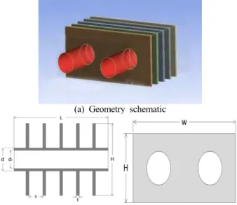
A detailed view of a plain-fin type heat exchanger situated around two tubes is shown in Figure 2. The plate-fin type heat exchanger is attached in the condensing section of the heat pipe, as shown above. The heat dissipation method using a plain-fin type is applied to a passive cooling method through a natural convection simulation. It is difficult to achieve an ac-
changer with two extended tubes if the computational domain is applied as shown in Figure 2. Thus, to analyze the geome- try, the number of fins is reduced to five. A general schematic of the computational domain geometry is shown in Figure 3.
The outer tube diameter (d) is 7.2 mm, and the inner tube di- ameter (di) is 6.8 mm. Based on the geometry, the plate-fin pitches, annular fin arrays, and plate dimensions are inves- tigated to obtain the optimum design parameters.
Figure 1: Schematic of a heat dissipation system
Figure 2: Schematic of a plate fin type heat exchanger
(a) Geometry schematic
(b) Plain-fin configuration geometry
Figure 3: Thermal modeling diagram of 5 plain-fin geome-
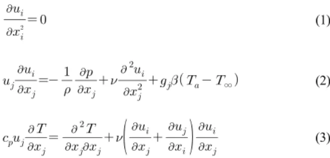
For a fluid domain, 3D governing equations for the con- tinuity, momentum, and energy of the natural convection are used as follows:
(1)
∞ (2)
(3)
where , and T are the velocity components, pressure, gravitational acceleration components, and fluid temperature, respectively. In addition, β, ρ, ν, cp and k are the volumetric thermal expansion coefficient, density, kinematic viscosity, specific heat, and thermal conductivity of a fluid, respectively, each of which is assumed to be a constant. For the fluid den- sity, an incompressible model for natural convection is used.
For a solid domain, a general 3D conduction equation is used. In this geometry, the computational domain contains both the fluid and solid parts. For the calculation, the finite volume element (FVM) of ANSYS Fluent is used for the 3D geometry of the conjugate heat transfer of the natural con- vection and a simulation of the fluid flow characteristics [8].
In the field of hydrodynamics, the pressure spatial discretiza- tion uses a body-force weighted scheme, and energy spatial discretization is used for a second upwind scheme.
Before the numerical results are analyzed, the geometry of a single horizontal bare cylinder is investigated to check the natural convection comparison with varying various grid numbers. The correlations used for a bare tube come from Churchill [9], i.e.,
Pr
(4) and Morgan's correlation [10], i.e., ∙ for ≤≤ (5) where the Rayleigh and Nusselt numbers are defined as follows.
(6)
(7)
The physical properties for calculating the Rayleigh and Nusselt numbers are considered for the film temperature, and where D is the outer diameter of the tube. The tube surface boundary condition assumed for the condensing section of a cylinder is a constant. The heat input through a tube surface equals the total heat transfer rate from a cylinder to the steady state surroundings.
Before conducting the analysis, various nodes are simulated to ensure the grid independence. After more than 0.5 million elements are simulated, the grid independence of the model is considered acceptable. Particularly around a cylinder, a higher grid density is implemented. For a comparison of a single bare tube, over one million elements are used.
Table 1 shows a comparison of theoretical and numerical Nusselt numbers in a single bare cylinder at Ra = × . In Table 1, the heat transfer comparison shows a good agreement. Thus, this single cylinder case is extended to a two-cylinder case in a plain-fin heat exchanger cooling system.
Churchill-
Chu [9] Morgan [10] Numerical
Nusselt number, Nu 22.31 21.95 21.36
Table 1: Comparison of theoretical and numerical Nusselt numbers
3. Results and discussion
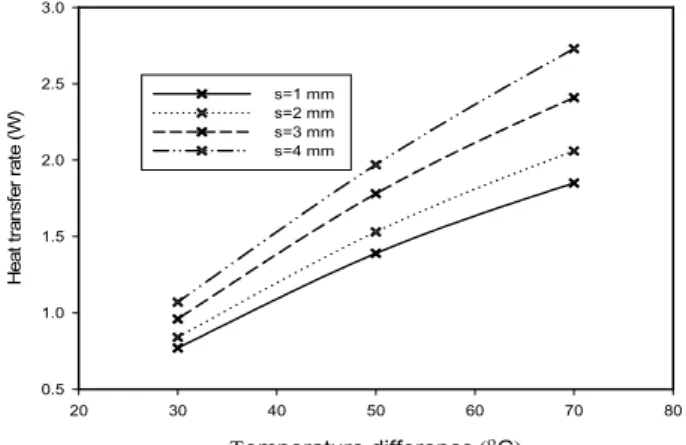
A plate-fin model in the condensing section of a vapor chamber heat pipe with two tubes, used to maximize the heat dissipation system, was investigated. To investigate several op- timal parameters affecting the heat transfer dissipation per- formance in a tube heat exchanger, the various temperature differences between the tube surfaces and ambient air were first considered. Figure 4 shows the heat transfer rates with varying temperature differences between the tube wall temper- ature (Tw) and ambient air temperature (Ta). The experimental boundary conditions of the cylinder surface temperature in the condensing section are shown through a linear profile from the end junction of the evaporating section to the end point of the condensing section [7]. The tube wall surface temperature was assumed to be a constant. The average difference in the base temperature determined through the experimental measurement was about 50 °C. In Figure 4, the temperature difference var- ies from 30 °C to 70 °C based on the tube surface temperature. The results indicate that the overall heat dis- sipation amount increased with increasing temperature differ- ences between the tube walls and ambient air. It appears that the flow characteristics changed from a channel flow to a
boundary layer flow. At 50 °C, the increment rate was 10.1%
for a fin pitch of 1 to 2 mm. The next increment rate was 16.3% when varying the fin pitch from 2 to 3 mm.
emperature differenceC
20 30 40 50 60 70 80
Heat transfer rate (W)
0.5 1.0 1.5 2.0 2.5 3.0
s=1 mm s=2 mm s=3 mm s=4 mm
Figure 4: Heat transfer rate with varying differences in tem- perature difference between the tube walls and ambient air
Next, the increment rate was 10.6% when changing the plain-fin pitch from 3 to 4 mm. Thus, the heat dissipation per- formance was the most effective when the plain-fin pitch was changed from 2 to 3 mm.
(a)∆ ℃
(b)∆ ℃
Figure 5: Cross-sectional temperature distribution around plain-fins and two tubes
Figure 5 shows the cross-sectional temperature distributions around plain-fins and two tubes for two different cases. The plain-fin material had a high thermal conductivity. Thus, the temperature of the plain-fin area itself had the same temper- ature profile with the exception of the bottom side edge of the plate. The top plain-fin area indicates that the overall iso-ther- mal temperature profiles clearly described the natural con- vection effect. When the temperature difference was 30 °C, the heat temperature profile of the upper section illustrates that the area of equal distribution was small. When the temperature difference was 70 °C, the upper section of the plain-fin in- dicates that the equal distribution of the temperature profile in- creased in area. In this case, a heat stagnation area appeared at the very end of the upper section, which is not shown in Figure 5. This indicates that for this particular case, the heat dissipation performance was insufficient. Proper management is therefore required.
Temperature difference (oC)
20 30 40 50 60 70 80
Heat transfer rate (W)
1.0 1.5 2.0 2.5 3.0
H=18 mm H=22 mm H=26 mm H=30 mm
Figure 6: Heat transfer rate with varying vertical plain-fin sizes
Figure 6 shows the heat transfer rates with varying plain-fin heights. The vertical plain-fin dimension was changed from 18 to 30 mm with increments of 4 mm. The changes in dimension are considered a possible plain-fin space occupation. For all changes in plain-fin height, the heat dissipation showed a linear profile when the temperature difference increased. At a temper- ature difference of 30 °C, the amount of heat transfer dissipation was minimal even when the size increased vertically. At temper- ature differences of 50 °C and 70 °C, the heat transfer rate in- creased slightly. However, the change in overall heat transfer rate was not very effective when increasing the vertical di- mensions of the plain-fins at the specific temperature difference.
Temperature difference (oC)
20 30 40 50 60 70 80
Heat transfer rate (W)
1.0 1.5 2.0 2.5
W=36 mm W=40 mm W=44 mm W=48 mm
Figure 7: Heat transfer rate with varying horizontal plain-fin sizes
Figure 7 shows the heat transfer rate with varying horizontal plain-fin sizes. As shown previously in Figure 6, even when the vertical plain-fin sizes increased, the resulting change in heat transfer rate was not large. At 50 °C, the increment varied 4.5%, 4.0%, and 2.1% for each change in width, respectively.
As shown in Figure 6, these changes were 3.2%, 1.9%, and 1.8% for each change in height, respectively. The rate of in- crease in height showed more effective results in terms of heat dissipation. This indicates that for the vertical direction, the generated heat flowed from the bottom of the plain-fins to the upper area through natural convection. Thus, the extended area of the upper area was not effective because the upper flow was already sufficiently hot. For the horizontal direction, the thermal performance of the extended surface area to a fluid area that was insufficiently heated showed a higher rate of increase in terms of the heat dissipation. Thus, a horizontally extended sur- face was shown to be more effective, and it was made clear that a change in the horizontal dimension of the plain-fins in a confined space area is more effective in a plain-fin heat ex- changer with two tubes.
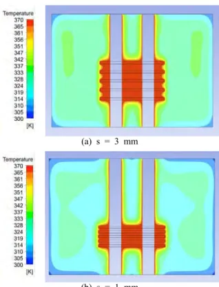
Figure 8 shows the temperature distributions of a cross- sec- tional area with varying plain-fin offsets. In Figure 8 (a), the temperature distribution around the plain-fins shows the same iso-thermal profile. This is a similar to when the plain-fin pitch was 1 mm (see Figure 8 (b)) because the thermal boun- dary layers along the vertical plain-fin direction were overlapped. Thus, the temperature of the heat dissipation of the fluid domain between plain-fins was similar to the temper- ature under changes in the plain-fin pitch.
(a) s = 3 mm
(b) s = 1 mm
Figure 8: Temperature distributions of a cross-sectional area with varying plain-fin offsets
s (mm)
0 1 2 3 4 5
Heat transfer rate (W)
0.5 1.0 1.5 2.0 2.5 3.0 3.5 4.0
(Tw-Ta)=70oC (Tw-Ta)=50oC (Tw-Ta)=30oC
Figure 9: Heat transfer rate of different plain-fin offsets with varying differences in temperature conditions
Figure 9 shows the heat transfer rate of different plain-fin offsets with varying differences in the temperature conditions.
The overall heat transfer rate with an increase in fin-offset dis- tance increased slightly. At ∆ ℃, the incremental ratio was 9.1%, 14.3%, and 11.5% with the respective increases in plain-fin pitch. It can be assumed that when the fin offset is small, the natural convection boundary layers between the
plain-fins will be overlapped. When the fin pitch changed from 2 to 3 mm, the effect on the heat dissipation was larger than for the other two cases. This means that even when con- densed fins were positioned to obtain the maximum heat dis- sipation performance, a 3 mm fin pitch appeared to be the most effective.
4. Conclusions
In this paper, the thermal characteristics of a plan-fin heat exchanger with two cylinders based on a computational fluid dynamics technique were presented. The effects of the temper- ature differences, fin offsets, and plain-fin sizes in confined spatial dimensions were investigated. The heat dissipation showed a maximum effect when the plain-fin pitch was changed from 2 to 3 mm. At ∆ ℃, a heat stagnation area appeared. For this case, the heat dissipation was insufficient. For a plain-fin configuration, the change in the horizontal dimension of the plain-fins is a more effective parameter. The temperature of the heat dissipation of the fluid domain between plain-fins has a similar iso-thermal profile with changes in the plain-fin pitch owing to the overlap in thermal boundary layers.
Acknowledgments
“This work was supported by the Pukyong National University Research Abroad Fund in 2011 (PS-2011-013)”
References
[1] B. Kundu and P. K. Das, “Optimum dimensions of plate fins for fin-tube heat exchangers,” Int. J. Heat and Flow, vol. 18, no. 5, pp. 530-537, 1997.
[2] H. Nemati and S. Samivand, “Simple correlation to evaluate efficiency of annular elliptical fin circum- scribing circular tube,” Arabian Journal for Science and Engineering, vol. 39, no. 12, pp. 9181-9186, 2014.
[3] M. Mon and U. Gross, “Numerical study of fin-spac- ing effects in annular-finned tube heat exchangers,”
International Journal of Heat and Mass Transfer, vol.
47, no. 8-9, pp. 1953-1964, 2004.
[4] A. Nuntaphan, T. Kiatsiriroat and C. C. Wang, “Air side performance at low Reynolds number of cross-flow heat exchanger using crimped spiral fins,”
International Communications in Heat and Mass Transfer, vol. 32, no. 1-2, pp. 151-165, 2005.
[5] B. Kundu and P. K. Das, “Approximate techniques for the performance analysis and optimization of
two-dimensional plate fins circumscribing circular tubes,” Heat Transfer Engeering, vol. 21, no. 2, pp.
19-28, 2000.
[6] B. Kundau, B. Maiti, and P. K. Das, “Performance analysis of plate fins in circumscribing elliptic tubes,”
International Journal of Heat and Mass Transfer, vol.
27, no. 3, pp. 86-94, 2006.
[7] J. S. Kim, J. Y. Bae, and E. Kim, “Analysis on the experimental cooling performance of a high power LED package with a crevice-type vapor chamber heat pipe,” Journal of the Korean Society of Marine Engineering, vol. 39, no. 8, pp. 801-806, 2015.
[8] ANSYS Inc., Ver. 16, www.ansys.com, Accessed August 1, 2015.
[9] S. W. Churchill and H. S. Chu, “Correlating equations for laminar and turbulent free convection from hori- zontal cylinder,” International Journal of Heat and Mass Transfer, vol. 18, no. 11, pp. 1049-1053, 1975.
[10] V. T. Morgan, “The overall convective heat transfer from smooth circular cylinder,” Advances in Heat Transfer, vol. 11, pp. 199-264, 1975.