CSR기반 좌굴 두께 요건을 고려한 이중선체유조선의 종방향 구조부재의 최적설계 연구
조영천
1
․ 이정철1,†
․ 이상복1
․ 신성광1
․ 장창두2
STX조선해양구조기술팀1
서울대학교조선해양공학과
2
Optimum Design for Longitudinal Strength Members of Double Hull Tankers with Central Long'l Bulkhead considering Buckling Thickness Requirement of Plate Panels based on Common Structural Rules
Young-Chun Jo
1․ Jung-Chul Lee
1,†․ Sang-Bock Lee
1․ Sung-Kwang Shin
1․ Chang-Doo Jang
2Structure Technology Team, STX Offshore & Shipbuilding, Changwon, Gyeongsangnam-do, Korea
1Dept. of Naval Architecture & Ocean Engineering, Seoul National University, Gwanak-gu, Seoul, Korea
2Abstract
The buckling assessment of plate panels described in common structural rules (CSR) is to be determined according to the buckling utilization factor with hull girder stresses calculated on net hull girder sectional properties. As the thickness requirement for the buckling assessment of plate panels is not explicitly given in CSR, a lot of time is spent to find the proper thickness of plate panels until reaching to an allowable buckling utilization factor. In this study, in order to reduce time and cost, the thickness requirement of plate panels satisfying buckling assessment was derived. The structural design system included with the thickness requirement for buckling assessment was developed. The system is called as Oil-tanker Automated Structural Investigation System (OASIS). The design result of longitudinal strength members using OASIS was verified by Nauticus Hull which is the rule scantling software of DNV. Finally, optimum design of a double hull tanker for the minimum weight using OASIS was presented.
Keywords : Common structural rules, structural design, oil-tanker; buckling assessment, OASIS, B : moulded breadth, D : moulded depth, L or L s : rule length, s : stiffener spacing, T bal : the minimum design ballast draught, T sc : the maximum design draught for the scantling, z NA-net50 : distance from the baseline to the horizontal neutral axis, σ yd : yield stress of the material
1. Introduction
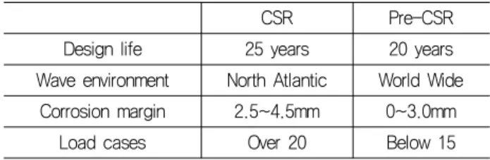
Common structural rules (CSR) applies to double hull oil tankers of 150m length and upward classed with the society and contracted for construction after 1st April 2006 (IACS, 2008). CSR is established by IACS (International Association of Classification Societies) in order to archive the goals of more robust and safer ships. Comparing with the rules of the classification societies before CSR (Table 1), the scantling requirements of CSR are more stringent and its procedures are more complex. The severe scantling requirements cause the increase of hull weight. The complexity of procedure causes the increase of man-hour for structural design.
Table 1 Comparison of CSR and pre-CSR
CSR Pre-CSR
Design life 25 years 20 years Wave environment North Atlantic World Wide
Corrosion margin 2.5~4.5mm 0~3.0mm
Load cases Over 20 Below 15
In design for longitudinal strength members of double hull tankers, the requirements except buckling assessment are expressed as the thickness requirement of plate panels.
However, the buckling assessment is expressed as whether
the buckling utilization factor is lesser than the allowable
buckling utilization factor. The buckling utilization factor is
calculated from hull girder bending stress and slenderness
factor which are obtained from the net thickness of plate panel. If thickness of plate panels doesn’t satisfy with buckling assessment, the following procedures of buckling assessment are repeated until buckling assessment of plate panels is satisfied by the proper thickness of plate panel.
z To assume the net thickness of plate panels
z To estimate hull girder bending stress and slenderness factor
z To calculate buckling utilization factor
In this paper, the thickness requirement of plate panels satisfying buckling assessment was derived. Due to the direct calculation of plate thickness to satisfy buckling assessment, time and cost for the structural design for CSR was reduced.
The CSR requirements of plate panels are also included in the system. The system is called as OASIS (Oil-tanker Automated Structural Investigation System). The result of structural design for the 73K panamax tanker using OASIS was verified by Nauticus Hull which is the software for the rule scantling of DNV. Optimum structural design for the minimum hull weight using OASIS was presented.
2. Scantling Requirements for Plate Panels of CSR
2.1 Corrosion margin and net thickness approach
CSR provides the corrosion margin, t corr , for typical structural elements in the cargo tank region as shown in Fig. 1.
Fig. 1 Corrosion margin for typical structural elements within the cargo tank
In order to assure sufficient strength during the designed life of the ship, the net thickness approach is used. The net thickness approach distinguishes between local and global corrosion. Local corrosion is defined as the uniform corrosion of the local structural elements, such as a single plate or a stiffener. Global corrosion is defined as the overall average corrosion of large areas such as the hull girder.
2.2 Minimum thickness requirement, t
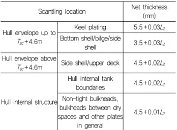
minMinimum thickness, which is independent of material and load, is based on service experience and is typically given in Table 2.
Table 2 Minimum net thickness for plating in the cargo tank region
Scantling location Net thickness (mm) Hull envelope up to
T sc +4.6m
Keel plating 5.5+0.03 L
2Bottom shell/bilge/side
shell 3.5+0.03 L
2Hull envelope above
T sc +4.6m Side shell/upper deck 4.5+0.02 L
2Hull internal structure
Hull internal tank
boundaries 4.5+0.02 L
2Non-tight bulkheads, bulkheads between dry spaces and other plates
in general
4.5+0.01 L
22.3 Proportions of plate panels, t
propThis requirement is non-stress based requirement. The re- quirement was typically defined as maximum allowable slenderness ratio. The thickness requirement is expressed as Eq. 1.
≥
(1)
where, C is slenderness coefficients.
2.4 Contact with q
uay, tquay (side shell)
This requirement applies to the side shell plates in contact with quay. It is to be applied to the extent of the side shell plating as shown in Fig. 2. Longitudinal extent is between a section aft of amidships where the breadth at the waterline exceeds 0.9B, and a section forward of amidships where the breadth at the waterline exceeds 0.6B. Vertical extent is between 0.3m below the minimum design ballast waterline, T bal , amidships to 0.25T sc or 2.2m, whichever is greater, above the draught T sc .
Fig. 2 Extent of side shell plating
The thickness requirement is given in Eq. 2.
≥
(2)
2.5 Requirement considering local pressure, t
localThis requirement is for preventing the yielding of plate panels from local pressure, P, for design load set being considered.
The thickness requirement is expressed as Eq. 3.
≥
(3)
Permissible bending stress coefficient, C a , and hull girder bending stress coefficient, σ hg , for the design load set being considered is expressed as follows.
(4)
(5)
Where,
α p : correction factor for the panel aspect ratio z : vertical coordinate of load calculation point y : transverse coordinate of load calculation point M v-total : design vertical bending moment
M h-total : design horizontal bending moment I v-net50 : net vertical hull girder moment of inertia I h-net50 : net horizontal hull girder moment of inertia
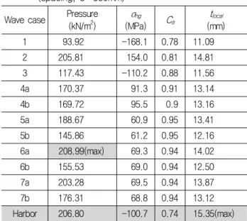
P, C a and σ hg are dependent on the design load set. Thus, the maximum thickness due to the local pressures is not induced at the maximum pressure, but induced by the combination of P, C a and σ hg as shown in Table 3.
2.6 Requirement for sloshing pressure, t
slhThis requirement is similar to the requirement for the local pressure, but the sloshing pressure is used instead of the local pressure. The thickness requirement is expressed as follows.
≥
(6)
Table 3 Example of the scantling requirement for the local pressures at the bottom plating on ballast condition (spacing, s=830mm)
Wave case Pressure (kN/m
2)
σ hg
(MPa) C a
t local
(mm)
1 93.92 -168.1 0.78 11.09
2 205.81 154.0 0.81 14.81
3 117.43 -110.2 0.88 11.56
4a 170.37 91.3 0.91 13.14
4b 169.72 95.5 0.9 13.16
5a 188.67 60.9 0.95 13.41
5b 145.86 61.2 0.95 12.16
6a 208.99(max) 69.3 0.94 14.02
6b 155.53 69.0 0.94 12.50
7a 203.28 69.5 0.94 13.87
7b 176.31 68.8 0.94 13.12
Harbor 206.80 -100.7 0.74 15.35(max)
2.7 Requirement for buckling assessment
This requirement applies to the plate panels subject to axial hull girder compressive stress and it needs to meet the following criteria.
≤
(7)
Allowable buckling utilization factor, η allow , is 1.0 for the plate panels at or above 0.5D and 0.9 for the plate panels below 0.5D.
Buckling utilization factor, η, is obtained as follows.
(8)
Hull girder compressive stress, σ hg-net50 , due to bending for the buckling assessment is to be calculated using the net hull girder sectional properties and is to be taken as the greater of the following.
(9)
(10)
Where,
M sw-perm-sea : permissible still water bending moment for seagoing operation
M wv-v : vertical wave bending moments k : higher strength steel factor
The critical stress of plate panels subject to compression is given as Eq. 11.
(11)
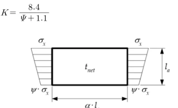
In the case that hull girder compressive stress is applied to plate panels as shown in Fig. 3, buckling factor, K, and reduction factor, C x , are given as Eq. 12 and 13, respectively.
(12)
Fig. 3 Plate penal subjected to compressive stress
(13)
Where, l a is stiffener spacing, α is aspect ratio and ψ is stress ratio.
Reference degree of slenderness, λ, is given as Eq. 14.
(14)
σ E is reference stress including net thickness of plate panel.
(15)
In order to assess buckling of plate panels by CSR, the procedure to calculate buckling utilization factor is summarized as follows. First, the net thickness of plate panel, t net , is determined by the former requirements. Subsequently, reference stress, σ E , and hull girder compressive stress, σ hg-net50 are
calculated according to the net thickness. In addition, buckling factor, K, is calculated by the geometry of plate panel and hull girder compressive stress distribution. Reference degree of slenderness, λ, is also calculated according to reference stress and buckling factor. Finally, buckling utilization factor, η, is obtained according to critical stress which is calculated by reduction factor, C x .
If the buckling utilization factor calculated by the former procedure is greater than the allowable buckling utilization factor, the procedure is repeated until buckling utilization factor satisfy buckling assessment. In other words, the net thickness of plate panels which satisfy buckling assessment is not directly obtained.
2.8 Derivation of thickness requirement for buckling assessment, t
buckThe thickness requirement of plate panel for buckling assessment is derived and suggested in following process.
Eq. 16 is obtained by combining Eqs. 7, 8 and 11.
≤
(16)
Substitute Eq. 13 for C x in Eq. 16, and multiply λ 2 to both sides. It becomes a second order inequality equation as follows.
≤ (17) Let b=η allow σ yd c, then Eq. 17 becomes
≤ (18)
Solve the second order inequality equation, and obtain Eq.
19.
≤ ≤
(19)
Using Eqs. 14 and 15, the equation of thickness requirement for buckling assessment is derived as follows.
≥
(20)
2.9 Determination of net thickness, t
netSteel plate for shipbuilding is typically produced by the 0.5mm. Thus, the required net thickness is determined by rounding the estimated thickness as follows.
First, maximum thickness, t max5 , except buckling assessment is obtained by Eq. 21.
(21)
Next, the net thickness, t net5 , except buckling assessment is given by rounding the calculated net thickness to the nearest half millimeter. For example:
(a) For 10.75≤ t max5 <11.25 mm the net thickness, t net5 , is 11.00 mm
(b) For 11.25≤ t max5 <11.75 mm the net thickness, t net5 , is 11.50 mm
The net thickness, t netb , for buckling assessment is given by rounding the thickness requirement for buckling assessment, t buck , to higher half millimeter. For example:
(a) For 10.00< tbuck ≤10.50 mm the net thickness, t netb , is 10.50 mm
(b) For 10.50<t buck ≤11.00 mm the net thickness, t netb , is 11.00 mm
Finally, the required net thickness, t net , is obtained as the larger value of t net5 and t netb .
(22)
3. Estimation of Cargo Tank Weight
The cargo tank weight, W tank , is the sum of the weight of longitudinals, W longi ., and the weight of transverse structural members, W trans ..
(23)
3.1 Weight of longitudinal structural members
The gross thickness, t gros , is obtained by adding the net thickness, t net , and the corrosion margin, t corr . The sectional area of the mid-ship section, A gros , is calculated based on the gross thickness. The weight of longitudinal members is obtained using the steel density, ρ steel , and the cargo tank length, L tank .
(24)
(25)
3.2 Weight of transverse structural members
Weight of transverse structural members, W trans , which consists of transverse web frames, W web , transverse bulkhead, W BHD and horizontal stringer, W str , as Eq. 26 was calculated by following estimation formula based on data of existing ships.
(26)
Weight of web frames is sum of weight of double bottom floors, side transverse, vertical transverse on longitudinal bulkhead and deck transverse.
(27)
× (28)
× (29)
× (30)
× (31)
×
(32)
× (33)
Where,
h D/B : height of double bottom floor b D/S : breadth of double side transverse s bot : long’l spacing in bottom plate
n web : number of web frames in cargo hold region
4. Oil-tanker Automated Structural Investigation System (OASIS)
4.1 Introduction
OASIS is developed for the structural design of the longitudinal
members to comply with the requirement of CSR. Fig. 4 shows
the main frame of OASIS. This system includes the scantling requirements of CSR and the thickness requirement for buckling assessment.
Fig. 4 Main frame of OASIS
4.2 Input data
Data input for the CSR scantling in OASIS is handled by several dialog boxes. Fig. 5 shows the dialog box for the main dimension input.
The dimensions of the mid-ship section in the cargo tank region are inserted in the dialog box as shown in Fig. 6. In the long’l spacing dialog box shown in Fig. 7, the number of longitudinal stiffeners is determined. When data input is com- pleted, the configuration of the mid-ship section is displayed as shown in Fig. 8.
Fig. 5 Main dimension dialog box
Fig. 6 Dialog box for the dimensions of the mid-ship section
Fig. 7 Long’l spacing dialog box
Fig. 8 Display mid-ship section by inputted data
4.3 Estimate CSR requirements
After data input, the estimation of longitudinal structural members is performed based on CSR. The estimation procedure is shown as Fig. 9.
Fig. 9 Procedure of calculate CSR requirements in OASIS
4.4 Display design results
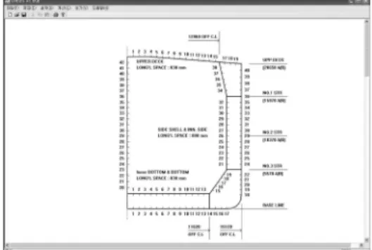
Upon completing the calculation of CSR requirements using OASIS, the design result of longitudinal structural members is displayed on the mid-ship section with the thickness of plate panels (Fig. 10).
OASIS supports GUI. When the left button is clicked on the plate panel, the pop-up window including the detail results of CSR scantling appears as shown in Fig. 11. Similarly, when the left button is clicked on the interested longitudinal stiffener, the pop-up window for the detail results of the stiffener appears as shown in Fig. 12.
Fig. 13 shows the hull girder properties such as cross sectional area, moment of inertia, section modulus and so on.
OASIS presents the plating and the stiffening calculation sheets as shown in Figs. 14 and 15.
Fig. 10 Display design result in midship section
Fig. 11 Display plating requirements
Fig. 12 Display long’l stiffener requirements
Fig. 13 Display hull girder properties calculation sheets
Fig. 14 Display plate calculation sheet
Fig. 15 Display stiffener calculation sheet
5. Design Results using OASIS
5.1 Target vessel
In order to verify the proposed thickness requirement and OASIS, the structural design of the longitudinal structural members for the 73K panamax product/crude oil tanker is performed.
Main dimensions of the vessel are shown in Table 4.
Table 4 Main dimensions of the 73K panamax tanker
Item Dimension Item Dimension
L
s(m) 216.25 T
sc(m) 14.30
B(m) 32.24 T
bal(m) 7.24
D(m) 20.65 V(knots) 15.00
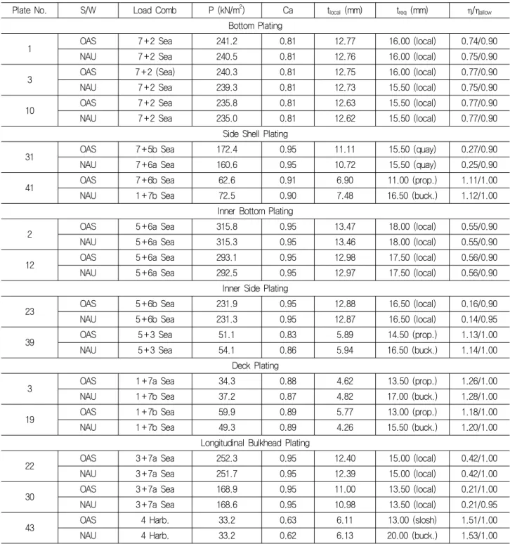
Table 5 Verification of design result without buckling assessment (OAS : OASIS, NAU : Nauticus)
Plate No. S/W Load Comb P (kN/m
2) Ca t
local(mm) t
req(mm) η/η
allowBottom Plating
1 OAS 7+2 Sea 241.2 0.81 12.77 16.00 (local) 0.74/0.90
NAU 7+2 Sea 240.5 0.81 12.76 16.00 (local) 0.75/0.90
3 OAS 7+2 (Sea) 240.3 0.81 12.75 16.00 (local) 0.77/0.90
NAU 7+2 Sea 239.3 0.81 12.73 15.50 (local) 0.75/0.90
10 OAS 7+2 Sea 235.8 0.81 12.63 15.50 (local) 0.77/0.90
NAU 7+2 Sea 235.0 0.81 12.62 15.50 (local) 0.77/0.90
Side Shell Plating
31 OAS 7+5b Sea 172.4 0.95 11.11 15.50 (quay) 0.27/0.90
NAU 7+6a Sea 160.6 0.95 10.72 15.50 (quay) 0.25/0.90
41 OAS 7+6b Sea 62.6 0.91 6.90 11.00 (prop.) 1.11/1.00
NAU 1+7b Sea 72.5 0.90 7.48 16.50 (buck.) 1.12/1.00
Inner Bottom Plating
2 OAS 5+6a Sea 315.8 0.95 13.47 18.00 (local) 0.55/0.90
NAU 5+6a Sea 315.3 0.95 13.46 18.00 (local) 0.55/0.90
12 OAS 5+6a Sea 293.1 0.95 12.98 17.50 (local) 0.56/0.90
NAU 5+6a Sea 292.5 0.95 12.97 17.50 (local) 0.56/0.90
Inner Side Plating
23 OAS 5+6b Sea 231.9 0.95 12.88 16.50 (local) 0.16/0.90
NAU 5+6b Sea 231.3 0.95 12.87 16.50 (local) 0.14/0.95
39 OAS 5+3 Sea 51.1 0.83 5.89 14.50 (prop.) 1.13/1.00
NAU 5+3 Sea 54.1 0.86 5.94 16.50 (buck.) 1.14/1.00
Deck Plating
3 OAS 1+7a Sea 34.3 0.88 4.62 13.50 (prop.) 1.26/1.00
NAU 1+7b Sea 37.2 0.87 4.82 17.00 (buck.) 1.28/1.00
19 OAS 1+7b Sea 59.9 0.89 5.77 13.00 (prop.) 1.18/1.00
NAU 1+7b Sea 49.3 0.89 4.26 15.50 (buck.) 1.20/1.00
Longitudinal Bulkhead Plating
22 OAS 3+7a Sea 252.3 0.95 12.40 15.00 (local) 0.42/1.00
NAU 3+7a Sea 251.7 0.95 12.39 15.00 (local) 0.42/1.00
30 OAS 3+7a Sea 168.9 0.95 11.00 13.50 (local) 0.21/1.00
NAU 3+7a Sea 168.6 0.95 10.98 13.50 (local) 0.21/0.95
43 OAS 4 Harb. 33.2 0.63 6.11 13.00 (slosh) 1.51/1.00
NAU 4 Harb. 33.2 0.62 6.13 20.00 (buck.) 1.53/1.00
5.2 Verification
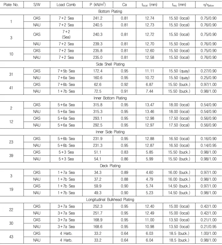
The structural design results from OASIS are verified by the rule scantling of Nauticus Hull. Table 5 shows verification of design results without buckling assessment. Table 6 shows verification of design results with buckling assessment. Whether the buckling assessment is considered or not, the OASIS results are virtually identical to the Nauticus ones. Therefore OASIS is a fully capable tool to carry out the CSR scantling design.
Note that, in some cases, OASIS outperforms Nauticus,
resulting in a better optimized scantling results shown as 1~2
mm less thickness around the deck panels when buckling
assessment is not considered. The reason is that Nauticus
isn’t able to consider the change of hull girder properties such
as cross sectional area, moment of inertia and section modulus
due to the change of plate panel thickness, while OASIS is
able to consider the change of hull girder properties due to
the change of plate panel thickness.
Table 6 Verification of design result with buckling assessment (OAS : OASIS, NAU : Nauticus)
Plate No. S/W Load Comb P (kN/m
2) Ca t
local(mm) t
req(mm) η/η
allowBottom Plating
1 OAS 7+2 Sea 241.2 0.81 12.74 15.50 (local) 0.75/0.90
NAU 7+2 Sea 240.5 0.81 12.73 15.50 (local) 0.76/0.90
3 OAS 7+2
(Sea) 240.3 0.81 12.72 15.50 (local) 0.75/0.90
NAU 7+2 Sea 239.3 0.81 12.70 15.50 (local) 0.76/0.90
10 OAS 7+2 Sea 235.8 0.81 12.60 15.50 (local) 0.75/0.90
NAU 7+2 Sea 235.0 0.81 12.58 15.50 (local) 0.76/0.90
Side Shell Plating
31 OAS 7+5b Sea 172.4 0.95 11.11 15.50 (quay) 0.27/0.90
NAU 7+6a Sea 160.6 0.95 10.72 15.50 (quay) 0.25/0.90
41 OAS 7+6b Sea 62.6 0.92 6.87 15.50 (buck.) 0.97/1.00
NAU 1+7b Sea 72.5 0.91 7.44 15.50 (buck.) 0.98/1.00
Inner Bottom Plating
2 OAS 5+6a Sea 315.8 0.95 13.47 18.00 (local) 0.54/0.90
NAU 5+6a Sea 315.3 0.95 13.46 18.00 (local) 0.54/0.90
12 OAS 5+6a Sea 293.1 0.95 12.98 17.50 (local) 0.56/0.90
NAU 5+6a Sea 292.5 0.95 12.97 17.50 (local) 0.56/0.90
Inner Side Plating
23 OAS 5+6b Sea 231.9 0.95 12.88 16.50 (local) 0.16/0.90
NAU 5+6b Sea 231.3 0.95 12.87 16.50 (local) 0.14/0.95
39 OAS 5+3 Sea 51.1 0.83 5.85 15.50 (buck.) 0.98/1.00
NAU 5+3 Sea 54.1 0.86 5.99 15.50 (buck.) 0.98/1.00
Deck Plating
3 OAS 1+7a Sea 34.3 0.89 4.60 16.00 (buck.) 0.97/1.00
NAU 1+7b Sea 37.2 0.88 4.79 16.00 (buck.) 0.98/1.00
19 OAS 1+7b Sea 59.9 0.90 5.74 14.50 (buck.) 0.97/1.00
NAU 1+7b Sea 49.3 0.90 5.23 14.50 (buck.) 0.98/1.00
Longitudinal Bulkhead Plating
22 OAS 3+7a Sea 252.3 0.95 12.40 15.00 (local) 0.42/1.00
NAU 3+7a Sea 251.7 0.95 12.49 15.00 (local) 0.42/1.00
30 OAS 3+7a Sea 168.9 0.95 11.00 13.50 (local) 0.21/1.00
NAU 3+7a Sea 168.6 0.95 10.98 13.50 (local) 0.21/0.95
43 OAS 4 Harb. 33.2 0.64 6.03 18.5 (buck.) 1.00/1.00
NAU 4 Harb. 33.2 0.64 6.04 18.5 (buck.) 0.98/1.00
5.3 Optimum design
OASIS includes the optimum design module which utilizes the parametric search method. Using this module of OASIS, the optimum design for the minimum weight of the target ship (73K P/C tanker) is performed over the design variables.
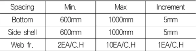
Table 7 shows the dimensions of the frame spaces for the target ship. The ranges of the design variables are shown in Table 8.
Fig. 17 shows the effect of bottom long’l spacing on the cargo hold weight. When bottom long’l spacing is 605mm, the cargo hold weight has the minimum value.
Fig. 18 shows the effect of side long’l spacing on the cargo hold weight. When side long’l spacing is 665mm, the cargo hold weight has the minimum value.
Fig. 19 shows the effect of web frame spacing on the
cargo hold weight. When web frame spacing is 3.9m, that is
equal to 6 web frames in a cargo hold, the cargo hold weight
has minimum value.
Considering all design variables, the minimum weight design is obtained as shown in Table 9. Weight saving is 54.54 tons per cargo hold. Since the panamax tanker has 6 holds, the total weight saving is about 330 tons.
Table 7 Framing spaces of target ship
Bottom Side shell Web frame
Spacing 830mm 800mm 6EA/C.H
Table 8 The ranges of design variable
Spacing Min. Max Increment
Bottom 600mm 1000mm 5mm
Side shell 600mm 1000mm 5mm
Web fr. 2EA/C.H 10EA/C.H 1EA/C.H
Table 9 Result of optimum design
Design Bottom
(mm)
Side (mm)
Web (m)
Weight (ton)
Existing 830 800 3.9 1310.28
Optimum 605 665 3.9 1255.74
Fig. 17 The effect of BTM long’l Sp. on the C/H weight
Fig. 18 The effect of side long’l Sp. on the C/H weight
Fig. 19 The effect of web frame sp. on the C/H weight
6. Conclusions
In the present study, OASIS was developed. OASIS included the requirements of CSR and the thickness requirement for buckling assessment of plate panels.
The main conclusions of this study can be summarized as follows:
z The thickness requirement for buckling assessment of plate panels is derived. It can be applied for the structural design of double hull oil tankers according to CSR.
z OASIS, which is a structural design system for double hull oil tankers, is developed. Since the design results of OASIS are verified by Nauticus of DNV, they satisfy CSR.
z The optimum design for the minimum weight of the 73K panamax tanker was performed, resulting in the reduction of 330 tons.
z OASIS is considered to be useful for the structural design of double hull oil tankers according to CSR.
References
IACS (2008). “Common Structural Rules for Double Hull Oil Tankers,” IACS
Karr, D. G, Beier, K. P., Na, S.S. and Rigo, P. (2002). “A Framework for Simulation Based Design of Ship Structures,”
Journal of Ship Production, Vol. 18, No. 1, pp. 33-46.
Seung-Soo Na and Hyoung-Geun Jeon (2008). “Optimum Structural Design of Mid-ship Section of D/H Tankers Based on Common Structural Rules,” Journal of the Society of Naval Architects of Korea, Vol. 45, No. 2, pp. 151-156.
조 영 천 이 정 철 이 상 복 신 성 광
장 창 두