- 21 -
the spot light into the line light
Kyu-Man Choi*, Hae-Chun Lee**
ABSTRACT
A CCFL which commonly used in the back light units for the LCD, possess very high brightness hence, was widely used as a line light source. However, the use of CCFL, caused for several environmental concerns since it contain highly toxic mercury, gradually replaced into a LED. But the LED is a spot light source, the dark area occurs in the surface of the back light units. In this paper, we proposed the lens that can convert the spot light into the line light and it can remove the dark area in the surface of the back light units. The lens is composed with the light condensation part and the light guiding part. The conditions obtained will be helpful to plan an optimum structure for such preparation.
Key-words : LED, LED Lens, BLU, LGP
Ⅰ. Introduction
The CCFL that possess high brightness has widely been used as a line light source in the back light units. However, the CCFL basically based on the mercury operated source hence, makes several environment concerns because of very high toxicity of mercury. The stringent regulations adopted by the EU, dictated to replace the use of CCFL. One of the possible alternate may be the LED type sources. Indeed, the LED source possess relatively very long life time i.e., about 100,000 hours, which is about 10 times higher than the CCFL.
Therefore, the LED light source may be very suitable light source for an ‘emergency exit’
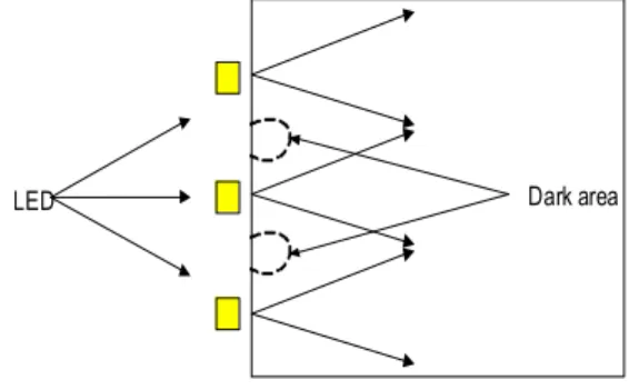
with substantially good reliability. But the use of LED as the light source for the back light, dark areas occurred as shown in fig.1. Hence, to overcome the problem one has to cover the dark area with black material. This may cause for decrease in effective lighting area.
The present investigation deals to propose an idea that can effectively convert the spot light source into the line light source.
LED Dark area
Figure 1: The positions of the dark area in the surface of the back light unit
Ⅱ. The structure of the lens Fig.2 shows the structure of the proposed lens in this paper.
This lens has two parts, one is upper structure which has curvature and the other is the light guide part which guides the light from the LED to the lens part
* 관동대학교 전자정보통신공학부 교수([email protected])
** 한국폴리텍Ⅱ대학 인천캠퍼스 전기계측제어과 교수([email protected])
It was made of PMMA (polymethyl metha crylate), i.e. optical resin materials that had high transparency and reasonable refractive in deres of 1.4.
Figure 2: The structure of the Lens.
Ⅲ. Fabrication and measurement
Three different samples, having different dimensions, were arranged. Using these samples, measured the characteristics of lights passed through the lenses (cf fig. 3).
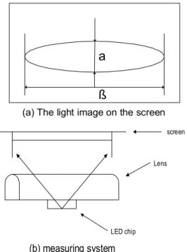
Fig 3(a) shows the light image of the LED passed through the lenses, α means the width of the image that is vertical to the lenses and β is the length of the image that parallel to the lenses.
a
ß
(a) The light image on the screen
screen
Lens
LED chip
(b) measuring system
Figure 3:The light characteristics measuring system
Lens(1) showed the characteristics of the light received from the lens which was 4mm length of the a. Lens(2) showed the characteristics of the lens which was 7.5mm length of the a. Moreover, lens (3) possessed the result of 15mm length of the a. These lenses were having same dimension of the d that is 6mm length and the C was also having same dimension that is 3mm length.
lens (1) lens (2) lens (3) distance
(a) 21
mm
(b) 28
mm
(c) 46
mm
(d) 53
mm
Figure 4: The light image of the different dimensions of the lenses
When the lenses were close to screen, the lens(1) which is 4mm length of the a showed circular like image on the screen and the lens(3) showed line like image on the screen.
When the lenses were moved from the screen, the lens(1) showed two circular image on the screen, and the lens(3) showed the result that the image was split into several line images.
But the lens (2) showed same images irrespective of the distance between the lens and the screen.
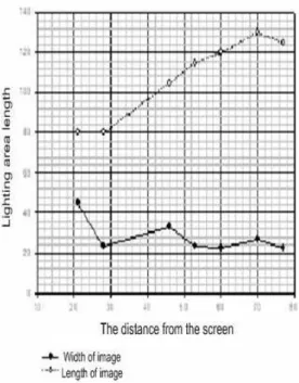
Figure 5: variation of the length and the width of the image on the screen.
Fig.5 revealed the variation of the length and the width of the image on the screen. By using the lens (2) which was 7.5mm length of the a.
The width of the light image came from lens was almost constant by varying the distance from lens to screen. These results indicate that a proper arrangement of the LED with this lens, one can make a line light source like the CCFL.
Fig.5 also showed that the lens structure to embody the lens converting the spot light into the line light must satisfy the conditions, i.e., the d is 6mm, the ais more than 4mm and lower than 15mm.
In this case, the length of the light guide was a-c, hence the relation of the a, c and d was:
The d is equal to 2c, and the relation of the a and the c is
The lens that satisfied the formula (2) possessed the characteristics to convert efficiently the spot light into the line light.
Fig 6 shows an example of the application of this lens.
This was compared with the common ones that using only LED lamps, without using any kinds of optical devices.
We can see the dark area in the fig 7(b) of the common
back light unit. But there is no dark area in the fig 7(a) using the lens developed in this study. It had even brightness uniformity and the brightness characteristics were better than that of common ones.
Figure 6: the back light unit with a developed
(a)
(b)
Figure 7: comparision results of the back light units.
POINT
0 2 4 6 8 10
휘도 cd/m2
240 250 260 270 280 290 300 310
Lens 유 Lens 무
Figure 8: The characteristics of the brightness uniformity
Ⅳ. Conclusion
A suitable arrangement has been proposed for the lens structure to convert efficiently a spot light source into a line light source.
Such arrangement contained two parts; one was light guide part which has the function guiding the light into the lens part.
The other was lens part focusing the light received from the light guide part.
To obtain same light characteristics of the CCFL, the following rule has to be satisfied:
The lens designed obtained by this condition can be used for the LCD back light source that could not have the dark area.
Acknowledgments
This work was supported by grant No. RTI 05-01-02 from the Provincial Technology Innovation program of the Ministry of Knowledge Economy (MKE).
References [1] SERI economic focus , 2007.04.24 [2] Strategies unlimited , 2006. 2007 [3] Digital times, 2008
[4] IT Soc magazine , 2008. vol. 23. pp.32 [5] Ogawa sin do "Side light type back light
units" patent review, 1999. 03. pp.2-4 [6] Noriyuki Nagai. " Light Design for Backlight
of LCD by Monte Carlo Simulation" J.
Illum. Engng. Inst. Jpn. Vol. 82, No.5, 1998.
[7] J.M. Tedesco, L.A.K. Brady, W. S. Colburn Kaiser Optical Systems, 8
[8] SERI economic focus , 2007.04.24 [9] R.Hicks, W. Halstead Lockheed/Sanders,
Nashua, NH "Development of a New Lamp Technology for Backlight Lcds", SID 93 DIGEST, pp. 21~24
[10] M. Anandan, D. C. Ketchum, H. Etlinger Thomas Electronics, PAW.N. Carr Microelectronics Center, JIT, Newark, NJ
"Design of a Multichannel True Fluorescent Lamp for Avionic TFT-LCD Back lighting
"Inc., Middletown, SID 93 DIGEST, pp.25~28.
저자약력
최규만(Kyu-Man Choi)
현재 관동대학교 공과대학 전자정보통신공학부 교수
<관심분야> 전자재료 이해춘(Hae-Chun Lee)
현재 한국폴리텍Ⅱ대학 인천캠퍼스
전기계측제어과 교수
<관심분야> 제어계측