Design of Grid Workflow System Scheduler for Task Pipelining
Lee, Inseon
*작업 파이프라이닝을 위한 그리드 워크플로우 스케줄러 설계
*
이 인 선
*Abstract
The power of computational Grid resources can be utilized on users desktop by employing workflow managers. It also helps scientists to conveniently put together and run their own scientific workflows. Generally, stage-in, process and stage-out are serially executed and workflow systems help automate this process. However, as the data size is exponentially increasing and more and more scientific workflows require multiple processing steps to obtain the desired output, we argue that the data movement will possess high portion of overall running time. In this paper, we improved staging time and design a new scheduler where the system can execute concurrently as many jobs as possible. Our simulation study shows that 10% to 40% improvement in running time can be achieved through our approach.
요 약
워크플로우 관리자는 대량의 계산용 그리드 자원을 데스크탑 컴퓨터에서 개인이 편리하게 워크플로우를 만들고 수행할 수 있게 해주는 유용한 도구이다. 보통 데이터는 스테이지-인, 프로세스, 스테이지-아웃의 순서로 순차적으 로 진행되며 워크플로우 시스템은 이 과정을 자동화해준다. 그러나 최근의 e-science에서는 사용되는 데이터 량이 급속하게 증가하고 있고 원하는 출력물을 얻기 위해 여러 번의 과정을 수행하면서 데이터 이동 시간이 전체 수행시 간의 많은 부분을 차지하게 되어 스테이징 과정의 개선이 중요한 이슈가 되고 있다. 본 논문에서는 스테이징 과정을 개선하고, 이를 이용하여 가능한 한 많은 작업들을 동시 수행시키는 스케줄러를 설계하였다. 또한 모의실험을 통해 제안한 스케줄러의 성능이 10~40%까지 향상됨을 보였다.
▸Keyword : 그리드(grid), 워크플로우(workflow), 작업파이프라이닝(task pipelining), 스케줄러(scheduler)
∙제1저자 : 이인선
∙투고일 : 2010. 04. 13, 심사일 : 2010. 05. 10, 게재확정일 : 2010. 05. 26.
* This work was supported by the Korea Research Foundation Grant funded by the Korean Government(MOEHRD)
(KRF-2007-611-D00027)
I. INTRODUCTION
In some scientific fields such as bioinformatics, biomedical informatics and geoinformatics where large data processing is essential, information technology is the driving force behind its rapid development. Workflow is concerned with the automation of procedures whereby files and data are passed between participants according to a defined set of rules. Workflow systems make complicated middleware infrastructure and common scientific tools easy to use for scientists and allow them to conveniently run their own scientific workflows with simple graphical interface[1]. In these systems, many interesting computations can be expressed conveniently as data-driven task graphs, in which individual tasks wait for input to be available, perform computation, and produce output. Most of the workflow systems have something in common in that the output files of a prior task need to be staged to a remote site before processing the task, and similarly, output files may be required by their children tasks which are processed on other resources. Therefore, the intermediate data has to be staged out to the corresponding Grid sites. The automatic intermediate data movement can be categorized into centralized, mediated and peer-to-peer. These approaches provide the partial or complete automation of intermediate data movement between interconnected tasks. However, if the posterior task require the output of the prior task, the posterior task cannot begin its execution until the prior task finishes its writing output. Furthermore, most of the workflow systems do not launch the posterior task even if the partial or complete result of the prior task is ready to feed to the posterior task.
In most of the scientific workflows, we cannot ignore the intermediate data movement which possesses high portion of running-time for e-science applications. Input/output data are becoming larger and larger time after time. Furthermore, we cannot
ensure that the compute nodes are equipped with large data storage to afford such large data files.
Therefore, we present here a new task pipelining framework for scientific workflow management systems. We took two separate phases in order to provide a fast file staging. First phase is to design a storage layer which helps the workflow manager to schedule several parallel jobs concurrently. A simplified task pipelining framework for workflow systems was developed in [2] and it is a simple distributed file system that supports various legacy applications without modification to the existing applications. It also provides a general framework independently of the workflow management systems being used. The storage layer can be described in a workflow specification and thus, a user is able to construct a task pipelining framework without any further efforts except presenting a workflow specification for the Pipe File System(PFS)[2].
Second phase is to have a job scheduler by utilizing the storage layer so that the total execution time will be reduced by maximizing the concurrency of adjacent jobs. Existing workflow schedulers do not consider the possible pipelining of several jobs. We use PFS's features in order to improve the execution time of the workflow process.
HVEM(High Voltage Electron Microscope)-Grid[3]
is our motivation of this work. HVEM-Grid is a Grid
collaboration framework for researchers to help
conduct biological experiments in a convenient
environment. HVEM-Grid system consists of three
components-Control System, Data Grid, and
G-Render aside from GAMA[4] which is used for
user authentication and authorization. In this paper,
we are interested in the image processing workflow,
G-Render, where the processes are tightly connected
in a sequential pipeline. In this workflow, the
posterior task cannot begin its execution until the
output file of prior step is ready to serve. Our
system can serve as a underlying file system for
each process. At first, PFS will be constructed by
running PFS server components. If a user submits a
rendering process, the job manager will first run the PFS Library so that subsequent file operations will be forwarded to the PFS. After constructing the PFS, for each processing step, the input file will be fed to the next step by writing the data through PFS. The PipeLined Scheduler(abbreviated as PLScheduler) waits for the PFS to trigger the availability of the output file of prior task. If such condition is met, the PLScheduler will launch the next process after receiving the trigger message.
In this paper, we developed a new scheduling algorithm which is called as PLScheduler and our simulation result shows that our scheduler exhibits better performance in most of the experimental settings.
This Paper is organized as follows. Section II gives a overview of the related work that has been studied so far. In Section III, we describe two components of our framework, PFS and PLScheduler in detail. Section IV explains the interaction of the components and we present several simulation results in Section V.
II. RELATED WORK
1. Storage Layer
It is well known that in scientific application executed on the Grid, the data movement as well as the job scheduling should be considered[5]. In fact, there have been several attempts to consider the data movement in the workflow management system.
In [6], when the tasks on the workflow are executed by the same machine the input and output is connected through a pipe. The examples of data streaming between the tasks that are executed by the separate machines are Threaded Data Streaming[7] and Styx Grid Service (SGS)[8]. The former aims at transferring the terabyte-scale simulation data to local analysis visualization cluster. It buffers as soon as the simulation data is
generated, and streams the data in the buffer to local machine through parallel thread. The latter streams the data between two service instances by using Styx protocol. Styx is a message-based protocol. If a SGS client sends request message, then a SGS server attaches the data chunk to the reply message. The simultaneous execution of multiple tasks connected by chain is possible through the latter. However, these two approaches necessitate the modification of the existing application. Therefore, these are not a satisfactory solution. In GriddLeS[9] (Grid applications using Legacy Software), they implemented a File Multiplexer, a module that maps file system primitives into either local or remote files, or allows communication with remote processes. Our framework differs from GriddLeS in that we provide a general framework for various workflow managers.
VLAM-G[10] uses dataflow between simultaneously executing distributed components as an execution driving activity. VLAM-G supports the data streaming by scheduling jobs according to the data flow. Our system is distinguished from VLAM-G in that scheduling strategies of legacy workflow managers can be easily integrated. In [2], a storage layer for e-science workflow management systems, called PFS is designed. PFS makes it easy to integrate IO layer with workflow scheduler through triggering interface.
2. Scheduler
Scheduling of computational tasks on the Grid is a complex optimization problem which is an ongoing research effort followed by many groups. Scheduling has been studied in various communities[11]-[14]. Yu et. al[15]
summarized various workflow scheduling methods according
to scheduling architecture, decision making, planning
scheme, strategies, and performance estimation. Static
scheduler utilizes static information or the result of
performance estimation. Most of the existing workflow
schedulers use static information as their basic
measurement. Dynamic schedulers use dynamic information
Fig. 1. Grid Workflow Architecture with PFS & PLScheduler
in conjunction with some results based on prediction. Since the execution environment becomes different minute by minute, they use monitoring services in order to retrieve dynamic information such as CPU usage, bandwidth, disk usage, etc. The Monitoring and Discovery System (MDS) of Globus Toolkit 4 allows users to discover what resources are considered part of a Virtual Organization (VO) and to monitor those resources. GridRod[16] is a new service oriented workflow-scheduling tool. It leverages the existing flexible IO mechanisms provided by GriddLeS to achieve runtime flexibility.
III. DESIGN
1. Storage Layer: PFS
We considered following properties in designing our system so that it can be adopted to many workflow management systems for various e-Science Grid applications.
First of all, we emphasized on supporting various legacy applications. Within a Grid environment, the vast majority of scientific applications executed by scientists can be considered legacy. Our design choice is to build a virtual storage layer for the existing workflow management systems as well as legacy applications. Since many legacy applications use POSIX API as their basic I/O operations, we support
them by adopting the FUSE as our basic client library. Our system is implemented as a user-level file system using FUSE kernel module. It operates on top of existing file systems such as ext3, reiserFS, etc. In essence, FUSE traps system calls and upcalls to the PFS Manager or PFS Data Server depending on the request. Therefore, users are not required to modify their applications to use our system in running their applications.
Secondly, we place our emphasis on flexibility. We expect to provide a general solution to the problems mentioned in Section I, independently of the workflow management systems being used. Therefore we design a general pipelining framework which can be easily integrated with other existing workflow systems. Our simple triggering interface enables scientists to deploy our system as they deploy their science applications.
Finally, usability is one of our important concerns. Our system is comprised of pure user-level applications. By this, we mean that our system can be described in a workflow specification and thus, a user is able to construct a task pipelining framework without any further efforts except presenting a workflow specification for the PFS.
There have been several researches that can be
applied to our pipelining framework. Our framework
can be implemented in a form of data distribution or data
dissemination middleware such as publish/subscribe
system (pub/sub), resource broker, or distributed file
system (DFS). We choose DFS as our basic framework for the following reasons. Firstly, many legacy applications deal with the I/O operations through POSIX API calls, and in this context, read and write calls are obviously invoked by the applications when users need to read/write input/output data. Pub/sub system simply forwards the published data to the subscribers right after the data arrival. Basically, it lacks the ability to transmit the requested amount of data afterwards.
Furthermore, in these systems, the structured directory management is not a trivial task. In addition, except for DFS, it is hard to avoid the modification of existing application source code.
This may cause a significant code rewriting process to the researchers. Thus, we have chosen DFS as our framework to support task pipelining.
PFS supports primitive operations of distributed file systems such as read, write, open delete, etc.
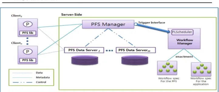
The architecture of PFS looks similar to Google File System in that one PFS Manager manages several PFS Data Servers in which physical files are actually stored. However, we have supplemented important features in order to easily integrate with existing workflow systems. Fig.1 describes Grid workflow architecture with PFS and PLScheduler at a glance. Server-side of a PFS consists of a single PFS Manager and multiple PFS Data Servers, on the other hand, client-side of a PFS consists of clients which access a PFS through FUSE library on behalf of the application. The PFS Manager maintains all DFS-related metadata, such as namespace, directory structure, and the mapping from files to PFS Data Server. A PFS Data Server stores the physical files in its storage and serves read/write requests from the clients. PFS Library includes a FUSE (Filesystem in user space) library and PFS Client, where the former intercepts the file input/output requests and the latter handles the requests interacting with the server-side components of PFS. PFS components are put together as a whole to provide the functionality such as directory
management, global naming, logical to physical file mapping, file archiving and schedule-triggering. The following sections describe the detailed explanation of each component. In section IV, we will illustrate the interaction of these components in detail.
1.1 PFS Manager
The PFS Manager is a resource manager for the PFS Data Servers. When a PFS Data Server is willing to provide its storage space with the users, it participates in the PFS system by registering itself in the PFS Manager. PFS Manager maintains the current PFS Data Server list in its memory. If a user is opening a file in read or write mode, the PFS Manager selects one of the PFS Data Servers and redirects the subsequent read/write requests for that file to the corresponding PFS Data Server. Directory management is another key feature that the PFS Manager provides. Although the physical files are actually distributed over the PFS Data Servers, the PFS Manager supplies a unified view of the current directory structure. To help the clients to view the file system as a single entity, the PFS Manager supports a global file naming scheme.
The PFS Manager is a single access point for the clients. A client can mount the PFS through the FUSE kernel module and manipulate the files as is usual with him. Metadata POSIX operations such as getattr, setattr, open, close are directly handled by the PFS Manager. PFS Manager also provides a triggering interface so that the various workflow managers may schedule the next task right after the redefined amount of data is ready to serve. This interface enables our system to easily integrate with existing workflow systems. In addition, PFS Manager supports data archiving to the underlying storage such as GridFTP. We regard the PFS as a temporary layer for a single scientific workflow.
Therefore, archiving intermediate and final data is an ultimate staging process for the entire job.
1.2 PFS Data Server
The PFS Data Server is responsible for storing
1: S
n← |V|
2: R ← N {number of Resources}
3: C
p← C
pis a subset of |E| {set of parallel edges}
4: C
s← C
sis a subset of |E| {set of sequential edges}
5: procedure schedule(A,i,j) 6: while S
n≠ Ø do
7: S
sj← 0 {set of sorted ready jobs}
8: S
sj← call(getReadyJobs, NULL) {get Sorted Ready Jobs}
9: R ← R + call(relinquishResources, NULL) {relinquish resources from done jobs}
10: SBF ← Ø {set of clustered jobs from BF traversal}
11: CBF ← 0 {total cost units for Breadth First}
12: SDF ← Ø {set of clustered jobs from DF traversal}
13: CDF ← 0 {total cost units for Depth First}
14: call(traverseBF, S
sj, CBF,SBF) 15: for each P
j∈ S
sjdo
16: CSDF ←0 {total cost units for Depth First for single seed}
17: SSDF ← Ø {set of clustered jobs from DF traversal for single seed}
physical files and handling read/write operations from clients. PFS Data Server stores physical files in its storage. When it begins its work, the PFS Data Server first registers itself to the PFS Manager.
When accessing a file for read/write, a client can identify through the PFS Manager the hostname and physical path of the file to access . Then, the PFS library, on behalf of the client, redirects the subsequent read/write requests to the PFS Data Server obtained from the previous step. The PFS Data Server serves the read/write request and transmits the requested data to the PFS Library.
When the predefined amount of data is available for a given file, it notifies the PFS Manager of the arrival of sufficient amount of data so that the PFS Manager may trigger the scheduling of the next task.
1.3 PFS Library
The PFS Library consists of FUSE kernel module and PFS Client. PFS does not deploy the FUSE kernel module since FUSE is being widely deployed in the main Linux distributions recently. When PFS Library first executes, it mounts the PFS on the given mount point so that subsequent file system access may be handled by the PFS system. Every POSIX API call is intercepted by the FUSE kernel module and it is redirected to the PFS Client. When opening a PFS file, the PFS Client first looks up the file by querying the PFS Manager and acquires the proper file handle which contains the PFS Data Server information to contact. This information regarding the open files is maintained by the PFS Client and subsequent requests are redirected to the appropriate PFS Data Server.
2. Workflow Scheduler: PLScheduler
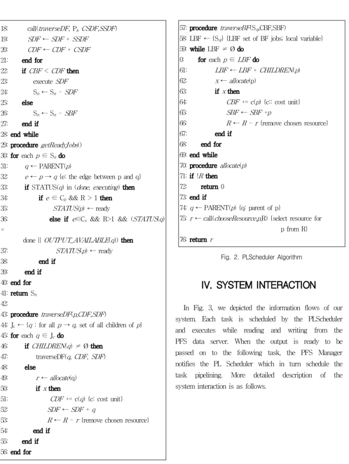
The PLScheduler basically follows GridRod[17], the dynamic workflow scheduler for GriddLeS[9]. In GridRod, they consider two possible concurrency - spatial and temporal concurrency. Spatial concurrency is achieved by executing all the components simaltaneously. This is represented in the workflow graph by breadth first traversal. On the other hand,
temporal concurrency depends on the IO behavior of the jobs. If two jobs can be executed concurrently, for example, they do not have IO dependency,
they are considered to be safe to run simultaneously.
GridRod improves the throughput by exploring both types of concurrency in order to optimize scheduling.
They developed variants of Breadth and Depth First
search approaches, which performs repeated searches
along the orthogonal directions until a halting
condition is encountered. We extended the GridRod
to achieve performance improvement by exploiting
the potential concurrency. Our algorithm begins with
a simple principle - execute jobs as soon as the data
is available. In order to improve performance, we
utilize the triggering interface of PFS. The detailed
scheduling algorithm is shown in Fig. 2.
18: call(traverseDF, P
j, CSDF,SSDF) 19: SDF ← SDF + SSDF
20: CDF ← CDF + CSDF 21: end for
22: if CBF < CDF then 23: execute SDF 24: S
n← S
n- SDF 25: else
26: S
n← S
n- SBF 27: end if
28: end while
29: procedure getReadyJobs() 30: for each p ∈ S
ndo 31: q ← PARENT(p)
32: e ← p → q {e: the edge between p and q}
33: if STATUS(q) in (done, executing) then 34: if e ∈ C
p&& R > 1 then
35: STATUS(p) ← ready
36: else if e∈C
s&& R>1 && (STATUS(q)
=
done || OUTPUT_AVAILABLE(q)) then
37: STATUS(p) ← ready
38: end if
39: end if 40: end for 41: return S
n42:
43: procedure traverseDF(p,CDF,SDF)
44: J
c← {q : for all p → q, set of all children of p}
45: for each q ∈ J
cdo
46: if CHILDREN(q) ≠ Ø then 47: traverseDF(q, CDF, SDF) 48: else
49: r ← allocate(q) 50: if x then
51: CDF += c(q) {c: cost unit}
52: SDF ← SDF + q
53: R ← R - r {remove chosen resource}
54: end if 55: end if 56: end for
57: procedure traverseBF(S
sj,CBF,SBF)
58: LBF ← {S
sj} {LBF set of BF jobs; local variable}
59: while LBF ≠ Ø do 0: for each p ∈ LBF do
61: LBF ← LBF + CHILDREN(p) 62: x ← allocate(p)
63: if x then
64: CBF += c(p) {c:: cost unit}
65: SBF ← SBF +p
66: R ← R - r {remove chosen resource}
67: end if 68: end for 69: end while
70: procedure allocate(p) 71: if !R then
72: return 0 73: end if
74: q ← PARENT(p) {q: parent of p}
75: r ← call(chooseResource,p,R) {select resource for p from R}
76: return r
Fig. 2. PLScheduler Algorithm
IV. SYSTEM INTERACTION
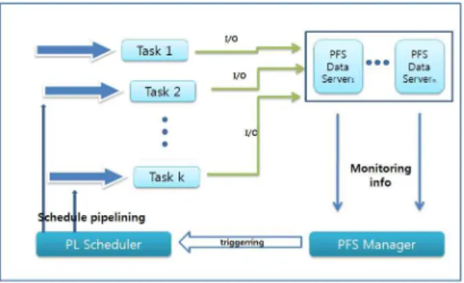
In Fig. 3, we depicted the information flows of our
system. Each task is scheduled by the PLScheduler
and executes while reading and writing from the
PFS data server. When the output is ready to be
passed on to the following task, the PFS Manager
notifies the PL Scheduler which in turn schedule the
task pipelining. More detailed description of the
system interaction is as follows.
Fig. 3. Information Flow between Components
1. Data Server Registration
Every PFS Data Server should inform the PFS Manager of its existence. When a PFS Data Server first starts up, it is initially given the address of the PFS Manager. With this information, it contacts the PFS Manager and sends its IP address. Receiving this information, the PFS Manager inserts an PFS Data Server entry into the data server list. This list is used in PFS Data Server selection during file creation.
2. Job Schedule Triggering
PFS not only acts as a distributed data storage, but also cooperates with a workflow manager to realize task pipelining. A typical workflow manager waits for the current running task to complete after activating the task. This structure makes matters hard to provide task pipelining since the workflow manager does not launch the next dependent task even if the current task has already finished its data writing.
In order to realize this concurrent execution, the workflow manager should notice the readiness of the interesting data. However existing workflow managers cannot determine whether the output file has arrived or not. In our system, since PFS manages all the I/O operations of the client, it can perceive the data arrival that will be provided as an input to the next task. Therefore, PFS Manager notifies the workflow manager of the data arrival
after it receives a predefined amount of data which is consistent throughout the system, which we refer to as schedule-triggering. For existing workflow managers, schedule-triggering is a signal that indicates the readiness of the minimal necessary data. If we incorporated the PFS and workflow manager in a single system, schedule-triggering would be noticed by the workflow manager itself. But we attach importance to the decoupling of workflow manager and PFS layer, otherwise, PFS layer will be dependent on a specific workflow manager, which is not desirable.
3. Read/Write Pipelining
Applications behave in a traditional way in which prior task writes output data and posterior task reads them as an input. In a traditional workflow system, the posterior task cannot execute until the prior task completes its execution and thus, the posterior task always sees the completed view of the data. But in our system, the posterior task begins its execution despite that the prior task is in the middle of writing the output data, once the schedule-triggering is delivered by the PFS Manager.
Therefore, the posterior task should acquire a refreshed view whenever the data is appended by the prior task. It is inefficient to update the posterior task's view whenever the data is written by the prior task. We, therefore, forces the posterior task to periodically update its view during the read process. In this way, prior task's output can be delivered to the posterior task concurrently.
4. Directory Management
Directory in PFS is a virtual resource maintained
for the user's convenience. Actual directory is stored
in PFS Manager's main memory in a hierarchical
structure like Linux directory structure, so that users
can access the directory in a usual way. Internally,
the directory is a hash table of (logical file name,
directory entries) pairs. Therefore, file lookup is a
simple process of retrieving a hash table entry.
V. Evaluation
1. Simulator
We implemented a event simulator that mimics the behavior of two scheduler, GridRod and PLScheduler. In [17], the authors indicate that analyzing the behavior of scheduling models on large and heterogeneous platforms such as a Grid is extremely difficult. A couple of reasons are explained in detail in their paper. They also developed a random workflow graph generator. The generator takes three parameters to construct the random workflow graph. Firstly, aspect ratio defines the ratio of breadth vs. depth in the graph, and is specified as a value between 0 and 1. If the value is 0, the depth of the graph becomes 1. Secondly, streaming factor is a probability measure of the streaming between workflow components. The value lies between 0 and 1, where in the former setting, all the edges are sequential edges and all the edges become parallel edges in the latter setting. The streaming factor specifies the degree of the parallelism that can be achieved.
name value
aspect ratio(ar) 0.2 ~ 0.8
streaming factor(sf) 0.3, 0.7
# of resource 10, 20
Table 1. Parameter values used in the simulation
Finally, number of resources determines how many resources are supplied in the current setting.
We generated a large number of workflow graphs with various parameter settings. We varied the aspect ratio and the streaming factor from 0.2 to 0.8 in order to show that our algorithm works in various workflow graphs. We set the number of resources 10 and 20. Also, we assign IO time to each task, which is extracted with uniform distribution between
95-99% of the processing time. For each setting, we repeated the simulation five times. We averaged and normalized the running time of GridRod and PLScheduler. Table 1 summarizes the parameters we used in the simulation.
2. Simulation Result
ar=0.2 ar=0.4 ar=0.6 ar=0.8
sf=0.3 22% 18% 19% 30%
sf=0.7 15% 13% 12% 40%
Table 2. Speedup of PLScheduler compared with GridRod
(# of resources = 10)
ar=0.2 ar=0.4 ar=0.6 ar=0.8
sf=0.3 24% 17% 21% 29%
sf=0.7 13% 10% 13% 35%
Table 3. Speedup of PLScheduler compared with GridRod (# of resource = 20)