Abstract
Structural bracing concept equipped with a new and efficient friction based energy dissipation device is referred to Friction Slip Brace (FSB) where the behavior of the brace components is elastic until the axial resistant force in the brace exceeds the friction force developed at the frictional interface of the device. In this study, the FSB concept is modified and new type of hybrid energy dissipation device, the Active Friction Slip Braces (AFSB), is described. The FSB is by far improved in the AFSB by inclusion of an active clamping mechanism on the friction interface. The clamping action regulated by the developed algorithm is altered during the response of the building. The results indicate that the action of dissipating vibrational energy in the AFSB impacts on the response at later cycles by keeping the drift amplitudes at much lower levels, revealing overshooting problem due to its early slippage. Providing predetermined constant incremental strengths to the building by AFSB members improves response by reducing drift amplitudes and base shear under small and medium amplitude ground accelerations.
요 지
일정한 크기의 마찰력을 도입한 가새(FSB)는 에너지를 소산시키는 효과적인 구조 부재이며, 가새의 축력 이 마찰력을 넘지 않을 때까지만 탄성 거동을 한다. 본 연구에서는 FSB 개념을 보다 확장시켜서 가새를 죄 는 마찰력의 크기를 능동적으로 변화시킬 수 있는 능동 조임 마찰 가새(AFSB)를 착상하여 단자유도 구조물 에 적용하고 조화 하중으로 기진시켜 그 거동을 시뮬레이션 하여 FSB와 비교 분석해본다. 이를 위해 간단하 고 효과적인 알고리즘을 개발해보았다. 연구 결과, 지반 가속도 값이 그다지 크지 않은 경우, AFSB는 초기 에 오우버슈팅이 발생하는 문제만 제외하고 FSB에 비해 효과적으로 진폭과 밑면 전단력을 감소시켰다.
Keywords : Bracing, Energy Dissipation, Active Clamping Mechanism 핵심 용어 : 가새, 에너지 소산, 능동적 조임 기구
능동 조임 마찰 가새로 보강한 단자유도 구조물의 응답
Vibration Control for a Single Degree of Freedom Structure Using Active Friction Slip Braces
이 진 호* 아크베이-제카이** 김 정 길*** 오 상 균****
Lee, Jin-Ho Akbay Zekai Kim, Jung-Gil Oh, Sang-Gyun
1)
* 정회원, 동의대학교 건축공학과 부교수 ** Chrysler Co. Michigan USA. Chief Engineer *** 정회원, 동의대학교 건축공학과 교수
**** 정회원, 동의대학교 건축공학과 조교수
2)
E-mail : [email protected] 016-9816-8282
•본 논문에 대한 토의를 2006년 2월 28일까지 학회로 보내 주시면 2006년 5월호에 토론결과를 게재하겠습니다.
1. Introduction
Passive Coulomb friction energy dissipation devices are described as a potentially feasible way of improving the structural performances and correcting the deficiencies of existing build-
ings(1,2). Structural bracing concept equipped
with a new and efficient friction based energy dissipation device is referred to Friction Slip Brace (FSB) where the behavior of the brace components is elastic until the axial resistant force in the brace exceeds the friction force de- veloped at the frictional interface of the de- vice(3). The friction force is provided by clamp- ing force normal to the friction interface by tightening the bolts placed in a transverse di- rection to the brace member axis and passing through the friction interface. The FSB devices used in current implementations are designed to operate only during the ultimate limit state re- sponse of the building. There is no functional expectation from these devices during the serv- iceability limit state response. To utilize the FSB device at maximum efficiency, slip loads should duplicate the story shear along the height of the building. Due to the uncertainty in the expected ground motion, distribution of story shear demand along the building profile cannot be accurately predicted. Thus, device oper- ation throughout the structure is uncertain, and damage to the structure may not be prevented.
In this study, the FSB concept is modified and a new type of hybrid energy dissipation de- vice, the Active Friction Slip Brace (AFSB), is described. The improvement in FSB is the in- clusion of an active clamping mechanism on the friction interface. The clamping action is altered during the response of the building in the AFSB. The change in the design will allow the
energy dissipation device to regulate the strength of the AFSB member during earth- quake action. Strength regulation is achieved by changing the clamping force over the friction in- terface to create the desirable axial strength for the AFSB member. This action is repeated throughout the ground motion depending upon the demand, and the response characteristics of the AFSB member are controlled.
2. Objectives
The objectives of this study are to describe the use of AFSB in building structures and to verify its effectiveness and feasibility under har- monic excitations as a preliminary substitute for seismic excitation. The design parameters of AFSB are defined, and the advantages of using AFSB are to be investigated by simulating its oper- ation on a single degree of freedom (SDOF) structure with the developed algorithm. The ef- fectiveness of AFSB during the service and dam- age state levels of the building is to be also verified. The structure is assumed resting on firm soils.
3. Solution Method and Response Characteristics of Active Friction Slip Braces
The Active Friction Slip Brace (AFSB) concept is developed from a Coulomb friction energy dis- sipater used in the Friction Slip Braces (FSB)(3). The AFSB includes a mechanism that can regulate the clamping force on the friction interface during the earthquake action.
3.1 Development of Operational Algorithm and Design Parameters for AFSB
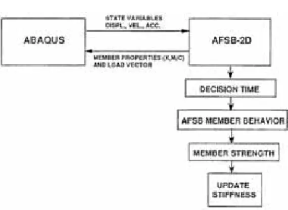
Fig. 1 Strength Increments of AFSB Fig. 2 Flowchart of AFSB-2D In the operational algorithm of AFSB, the
maximum axial load capacity of the brace is divided into predetermined increments as shown in Fig. 1. There are two basic design parame- ters associated with the operational algorithm.
The first design parameter is the decision time interval, ts. This is the minimum time interval be- tween two subsequent actions as dictated by the algorithm. The status of the AFSB is monitored at each ts and the necessary action to lower or increase the clamping force is taken. Two different states of the AFSB are checked at each ts. In other words, the AFSB may be in a state of slippage along the frictional interface device at that time. The other state is the reverse condition where the AFSB may not be in a state of slippage at that particular time. At each time interval ts, a decision is made on the mod- ification of the clamping force depending upon the cur- rent status. The decision in this study is very simple:
if at the time of decision the friction interface is at slip state, then the clamping force is increased one in- crement, ΔR. The clamping force increments are as- sumed to be constant in all cases. The second AFSB design parameter describes the incremental change in
brace strength, and it can be normalized with strength Ry (the level of maximum allowed brace load) of the brace component defining the ratio of strength incre- ment to maximum strength of the brace.
3.2 Development of a Solution Tool
In this study, a numerical analysis tool was developed to model the nonlinear behavior of the AFSB member for verification purpose using the user-defined element capability of ABAQUS.
The nonlinear user elements were defined in a user subroutine UEL(user-defined element li- brary)(4).
The feature of the AFSB requires the monitor- ing of all solution-based variables such as 1) displacement, velocity, acceleration, and axial force, 2) the force-displacement relationship of the AFSB member, and 3) the state (slippage or no-slippage) of the AFSB member throughout the time history analysis.
The basic flowchart for the AFSB-2D interface subroutine is given in Fig. 2. A complete listing of AFSB-2D with explanatory comments on the operations performed is not given here on ac- count of limited space.
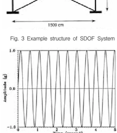
Fig. 3 Example structure of SDOF System
Fig. 4 Constant Harmonic Ground Acceleration
3.3 Response Analysis of SDOF Structure Subjected to Harmonic Excitations and Results
The structure is a portal frame with span of 15.0m, and column height of 5.0m as given in Fig. 3. The beam and column sections chosen were H-300×150×6.5×9 and H-300×150×5.5×8 respectively. The cross sectional area of the brace member is 3.23cm2. Total mass of the building was modeled as two equal concentrated masses at the free joints, moving only in the horizontal direction.
A constant amplitude harmonic ground accel- eration with frequency matching the building was applied as given in Fig. 4. Two different amplitude levels (5% and 20% of the gravita- tional acceleration, g) were used as the input ground acceleration.
The lateral load carrying capacity of the building was designed for a base shear co- efficient of 0.2, which corresponds to an axial load capacity of 65 kN for the braces. Thus, the slippage of the FSB member starts when its axial road reaches 65 kN(3).
Four different values of the decision time in- terval were considered: 0.015, 0.02, 0.03, and 0.06 second. They correspond to 40T, 30T, T20, and 10T respectively, where T is the fundamental period of the structure. The strength increment of the AFSB members were constant and were a fraction of the maximum strength of the AFSB member. Five differ- ent values, R5y, R10y, R15y, R20y and R25y were consid- ered, where Ry is the maximum strength of the AFSB member.
Drift time history of the AFSB and FSB type building subjected to 5% g amplitude harmonic
ground acceleration are compared in Fig. 5.
From this figure, the maximum drift level ach- ieved by the AFSB building was always smaller than the FSB building for all of the different combinations of design parameters, and the AFSB building with minimum strength incre- ment ( R25y) had the best response among the other strength increments for all ts. This effect is also ob- served in the cumulative energy time histories of the AFSB and FSB members given in Fig. 6. During the first second of the response, the FSB member remains elastic and does not dissipate energy. Meanwhile, the AFSB member starts slipping at all levels of the brace axial load as described by the strength increment parameter. During this early energy dissipation, the re- sponse amplitude of the AFSB member overshoots the FSB one as observed in Fig. 5, especially for the cas- es with small strength increments. But the action of dissipating vibrational energy early impacts on the re-
Fig. 5 Drift Time Histories of FSB and AFSB Buildings
Fig. 6 Cumulative Energy Time Histories of FSB and AFSB members
Fig. 7 Drift Envelops of FSB and AFSB Buildings
Fig. 8 Axial Force Time Histories of FSB and AFSB Buildings
sponse at later cycles by keeping the drift amplitudes at much lower levels.
The maximum drift levels of the AFSB build- ing with different design parameters are com- pared with the FSB building in Fig. 7.
Maximum drifts of the AFSB building are al- ways below the FSB drifts. During the slippages of the AFSB member, the effective period of the building is defined by the stiffness character- istics of the frame without structural bracing members. Therefore, during slippage, the effec- tive period of the building is longer than its ini- tial elastic period. This is also true for the be- havior of the FSB building. When the FSB member starts slipping, the bracing does not
contribute to the total stiffness of the building.
When the effective period of the building is in- creased, response amplification is decreased.
Since the FSB building slips less during its re- sponse, the reduction in its amplification is smaller than the AFSB building, which slips more often during the early phases of its response. This mechanism for initiating the ear- ly energy dissipation in the AFSB building en- ables it to complement the elastic range re- sponses of the FSB buildings.
The axial load time history of the AFSB mem- ber are compared to the FSB axial load in Fig.
8. It indicates that the axial loads of the AFSB members are smaller than the FSB members.
Fig. 9 Base Shear Envelops of FSB and AFSB Buildings
Fig. 10 Axial Force-Drift Relationships of FSB and AFSB Buildings
The AFSB building's maximum base shear is compared to the FSB building in Fig. 9. The AFSB building's maximum base shear decreases with decreasing strength increments and in- creasing decision time intervals.
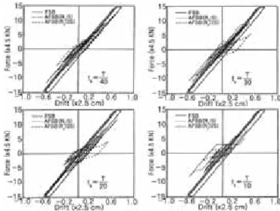
The axial force-lateral drift relationships of the AFSB and FSB members are given in Fig.
10. Five percent g amplitude of the resonant action initiates slippage in small amounts in the FSB members, whereas the AFSB members slip regularly at all axial load levels controlled by the strength increment parameter. The brace axial load maximum level is reduced as the strength increments are reduced and as the de- cision time interval are increased.
Fig. 11 Drift Time Histories of FSB and AFSB Buildings
Fig. 12 Axial Force-Drift Relationships of FSB and AFSB Buildings
Drift time histories of the AFSB and FSB buildings subjected to 20% g amplitude resonant harmonic ground acceleration are compared in Fig. 11. The FSB member slippage starts at 0.02 second. The FSB members slip consid- erably during repeated cycles, as seen in the axial force-lateral drift relationships in Fig. 12.
The multiples slip cycles dissipate significant amounts of energy at the friction interface. The AFSB building's maximum drift levels with vari- ous design parameter values are compared to those of the FSB building in Fig. 13. The AFSB building's maximum drift is below the FSB building as the decision time interval and the strength increment decrease.
Fig. 13 Drift Envelopes of FSB and AFSB Buildings
Fig. 14 Axial Force Time Histories of FSB and AFSB Buildings
The maximum drifts of the AFSB and FSB buildings are equal in order of magnitudes, yet the comparisons of total drift time histories for both buildings indicate the superior behavior of AFSB building. The AFSB building drift exceeds that of the FSB building during the first re- sponse cycle. The FSB building slips within the early phases of the first response cycle and starts dissipating energy. Since the level of ax- ial load is greater than the axial load levels of the AFSB building, the FSB building dissipates more energy within the same cycle. But this early overshooting of the response reduces the amplitudes of the next response cycles. This can be observed in the comparative drift response given in Fig. 11.
Fig. 15 Base Shear Envelopes of FSB and AFSB Buildings
The Axial load time histories of the AFSB member are given and compared with the FSB member in Fig. 14. The axial load amplitudes of the AFSB member are smaller than the FSB member, especially for smaller strength incre- ments and larger decision time intervals.
The maximum base shear levels reached by the AFSB buildings for different buildings for different design parameters are compared with the FSB's base shear level in Fig. 15. The AFSB building's maximum base shear is less than the FSB building's.
4. Conclusions and Future Study
The study shows that the AFSB building be- haves more efficiently compared to the FSB building subjected to harmonic excitations, and its earlier energy dissipation reduces response significantly. The computer simulation indicated that the response amplitudes were more effec- tively controlled for smaller strength increments and larger decision time intervals in the devel- oped algorithm. The AFSB member with the developed algorithm might be a useful tool to upgrade the seismic resistance for both newly constructed buildings and the existing buildings.
However, as mentioned in results of the simu-
lations, early slippage of AFSB members cause overshooting of the response compared to FSB under large amplitude ground excitation. The operational algorithm of the AFSB members should be modified to prevent it, which will be focused on the next phase of this study. Also, the modified algorithm will be applied rigorously to the AFSB members with various magnitude of seismic excitations.
감사의 글
본 연구는 2004년 동의대학교 교내 지원금으로 수행 되었음. Grant No. 2004AA123.
Reference
1. Pall, A.S. and Marsh. C., “Response of Friction Damped Braced Frames.”, Journal of the Structural Division, ASCE, Vol, 108, ST6, June 1982.
2. Austin, M.A., and Pister, K.S., “Design of Seismic Resistant Friction Braced Frames”, Journal of the Structural Division, ASCE, Vol. 111. pp. 2751-2769, 1985..
3. Shittaker, A.S., Bertero, V.V., Aktan, H.M., and Giacchetti, R., “Seismic Response of a DMRSF Retrofitted with Friction-Slip Devices”, Proc. EERI Annual Conference, Feb. 9-12, 1989, San Fransisco, CA.
4. ABAQUS, Users Manual, Version 4.8, Hibbit, Ka4lsson & Sorenson, Inc., 1989.
(접수일자 : 2005년 3월 10일)