硏究論文
고체추진기관의 Al 2 O 3 가 고무내열재에 미치는 영향을 평가하는 시험방법 연구
이형식*
†
․ 강윤구* ․ 임수용* ․ 오종윤* ․ 이경훈*A New Test Method to Evaluate Influence of Al 2 O 3 to Rubber Insulator in Solid Propellant Rocket Motor
Hyungsik Lee*
†
․ Yoongoo Kang* ․ Sooyong Lim* ․ Jongyun Oh* ․ Kyunghoon Lee*ABSTRACT
In solid propellant rocket motors, Al
2
O3
, one of combustion products, can be accumulated inside a combustion chamber. A special rocket motor was designed and tested to simulate thermal reaction of rubber insulator affected by the deposited slag. We successfully demonstrated through a dynamic radioscopy that the slag was deposited at the location as designed. In this paper we present a new test method which can simulate a high temperature and pressure environment in combustion chamber to evaluate material characteristics of rubber insulator and can provide design data to decide its thickness for a new solid rocket motor. The solid rocket motor, which has an average chamber pressure of 770 psia and a burning time of 50 seconds, was tested. The results show that erosion of EPDM insulator is more affected by a gas velocity rather than by the thermal reaction of slag with a high thermal capacity.초 록
고체추진기관의 연소 생성물 중 Al
2
O3
는 노즐목으로 빠져나가지 않고 연소관내부에 침적될 수 있다.침적된 슬래그에 의한 고무내열재의 열반응을 모사하기위하여 특별한 추진기관을 설계하여 시험하였다.
이 특별한 추진기관 시험 중 슬래그 침적양상을 Dynamic Radioscopy로 촬영함으로서 처음 설계한데로 원하는 위치에 슬래그가 침적된다는 것을 입증하였다. 본 논문에서 개발한 시험방법은 새롭게 설계하려 는 추진기관내부의 온도와 압력을 그대로 모사할 수 있어 슬래그에 의한 고무내열재의 재료 특성평가 및 연소관의 내열고무두께를 결정하는 설계자료로 사용할 수 있는 모사시험 방법이다. 연소평균압력 770 psi이고 연소시간 50초인 추진기관을 시험하였다. 시험 결과로부터 EPDM 내열재의 삭마는 열량이 큰 슬래그에 의한 고무 열반응보다는 연소가스 유속에 의하여 더 크게 영향 받는 것을 알 수 있었다.
Key Words: Al
2
O3
(산화알루미늄), Slag(슬래그), Solid Rocket Motor(고체로켓모터)접수일 2010. 12. 6, 수정완료일 2011. 4. 13, 게재확정일 2011. 4. 19
* 정회원, 국방과학연구소 1기술연구본부 6부
†교신저자, E-mail: [email protected]
[이 논문은 한국추진공학회 2010년도 추계학술대회(2010. 11. 25-26, 제주 샤인빌리조트) 발표논문을 심사하여 수정
・
보완한 것임.]1. 서 론
고체추진기관의 추진제 성분중 Al 파우더는
Al 표면에서부터 반응하여 Al
2
O3
가 되는 것으로 알려져있다.[1, 2] 이 Al과 Al2
O3
로 구성된 액적 은 고온에서 액상으로 존재하고 산화반응 하면 서 연소관 내부를 지나 노즐 밖으로 나간다. 연 소관 내에서 이 액적은 서로 뭉치고 부서지면서 노즐목을 통과하고 빠져나가지 못한 것들은 연 소관 내부에 남게 된다. 연소관내부에 남은 이 슬래그는 밀도가 커 성능에 크게 영향을 미치며, 열량이 높아 연소관의 고무내열재에 악 영향을 미칠 것으로 생각할 수 있다.따라서 연소모델링을 통하여 Al의 반응 메 카니즘을 연구하고 액적의 초기 크기분포를 구하고[3, 4] 이것들이 움직이면서 뭉치고 부 서지는 메카니즘을 연구하여 연소관에 침적되 는 메카니즘연구가 활발히 진행되고 있다[5, 6]. 또한 고체추진기관의 연소가스를 포집하여 이연구의 타당성을 입증하고 있으며, 추진기관 에 슬래그가 쌓이는 속도를 측정함으로서 슬 래그가 쌓이는 메카니즘을 증명하고 있다[7-9].
그러나 슬래그 생성과정에 기여하는 모든 인 자를 현재의 기술로 모델링 하는데 한계가 있 어 시험을 통한 확인이 필요하다고 알려져 있 다[10].
연소모델, 반응메카니즘, 유동해석을 통합하 여 슬래그가 쌓이는 과정을 연구하는 것은 차 후 진행하기로 하고 본 연구에서는 연소관에 침적된 슬래그가 연소관 내부 고무내열재에 어 떤 영향을 미치는 가를 연구하였다. 연소가스중 밀도와 모멘텀이 큰 Al과 Al
2
O3
로구성된 액적 이 부딪혀 액상으로 포집할 수 있는 U-tube를 연소관에 장착하여 슬래그를 생성시켰고, 이 슬 래그가 중력에 의하여 아래로 모이게 함으로서 설계하려는 추진기관의 연소온도와 압력에서 슬래그와 고무내열재가 서로 만나도록 설계하 였다. 즉, 설계하려는 추진기관이 작동할 때, 연 소관 내부에 침적된 슬래그가 내열고무에 미치 는 영향을 모사하여 설계에 활용할 수 있도록 하였다.이와 같은 연구는 세계적으로 처음 시도된 것 이며, 새로운 추진기관을 설계할 때 이 모사방법 을 적용하여 보다 타당한 내열고무 두께설계가
가능하다. 즉, 이 시험방법은 연소관내 환경을 거의 동일하게 모사함으로써 실기형 추진기관을 시험하기 전에 고무의 열적환경을 모사할 수 있 다는 장점이 있다.
2. 실 험
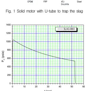
설계하려는 연소압력과 온도하에서 슬래그를 포집하기 위하여 Fig. 1과 같은 고체 추진기관을 설계하였다. End Burning 모터로 설계함으로써 모사 대상 추진기관의 시간/압력을 맞출 수 있 도록 하였다.
Figure 2와 3은 연소평균압력 770 psi이고 연 소시간 50초인 개발 모터를 모사하기위한 연소 압력과 추력설계이다.
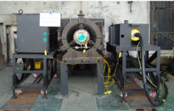
연소시험중 밀도가 큰 슬래그가 포집되는 거 동을 확인하기위하여 Fig. 4, 5와 같이 Dynamic Radioscopy (DR)장비를 설치하였다.
Fig. 1 Solid motor with U-tube to trap the slag
0 10 20 30 40 50 60
0 200 400 600 800 1000 1200 1400
P
C(p si a)
t (sec)
SLAG-0803
Fig. 2 Pressure design of test motor
0 10 20 30 40 50 60 0
50 100 150 200
F (l b f)
t (sec)
SLAG-0803
Fig. 3 Thrust design of test motor
Fig. 4 Top view of installations for test
Fig. 5 Photograph of installations before test
3. 결과 및 고찰
Figure 6과 7은 연소시간을 달리한 두 가지 시 험 결과를 보여주는 것으로서 예측치(Fig. 2, 3) 와 거의 일치함을 알 수 있다.
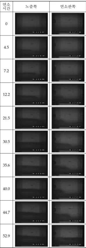
DR 장비의 계측한계로 인해 Fig. 4와 같이 U-tube부위중 절반만 찍을 수 있음으로 노즐쪽 과 연소관쪽으로 나누어 두 번 시험 하였으며, 이두번의 시험 결과를 같은 시간대로 재구성하 여 Table 1에 종합하였다. Table 1은 시간별 슬 래그의 위치를 보여주며 슬래그는 연소시간 4.5 초부터 노즐쪽부터 쌓이고 양이 많아짐에 따라
0 20 40 60 80 100 120 140 160 180 200 220 240
0 5 10 15 20 25 30 35 40
0 100 200 300 400 500 600 700 800 900 1000 1100
1200 SLAG2-0801('08.9.11.)
Pressure
T h rust (lbf)
Pressure(psig)
Time(sec)
Thrust
Fig. 6 Time vs. pressure and thrust curve in the case of 27 sec burning
0 20 40 60 80 100 120 140 160 180 200 220 240
0 10 20 30 40 50 60 70
0 100 200 300 400 500 600 700 800 900 1000 1100 1200
Pressure
Thrust(lbf)
P ressure(p si g)
Time(sec)
Thrust
SLAG2-0802('08.9.11.)
Fig. 7 Time vs. pressure and thrust curve in the case of 54 sec burning
연소
시간 노즐쪽 연소관쪽
0
4.5
7.2
12.2
21.5
30.5
35.6
40.0
44.7
52.9
Table 1. Dynamic radioscopy result of Slag deposition 연소관쪽으로 밀리는 현상을 관측할 수 있었다.
처음 12초 이후에는 절반이상이 슬래그로 쌓이 고 30초 이후에는 유속이 빠른 부위를 제외하고 전면을 슬래그가 덮고 있으며 유속에 의하여 끝 단이 움직이다가 연소가 끝나는 시간인 52.9초 이후에는 슬래그가 전면에 퍼짐을 볼 수 있다.
Figure 8은 의도대로 연소관쪽에는 슬래그가 쌓이지 않았음을 보여준다. Fig. 9는 전방내열재 (I)가 시험시간동안 1차 노즐목 역할 및 연소관 과 U-tube사이 격리 역할을 충분히 수행하였음 을 보여준다. Fig. 10은 시험시간동안 고속의 연 소가스와 부딪히는 부분이 삭마가 일어났지만 의도대로 Al
2
O3
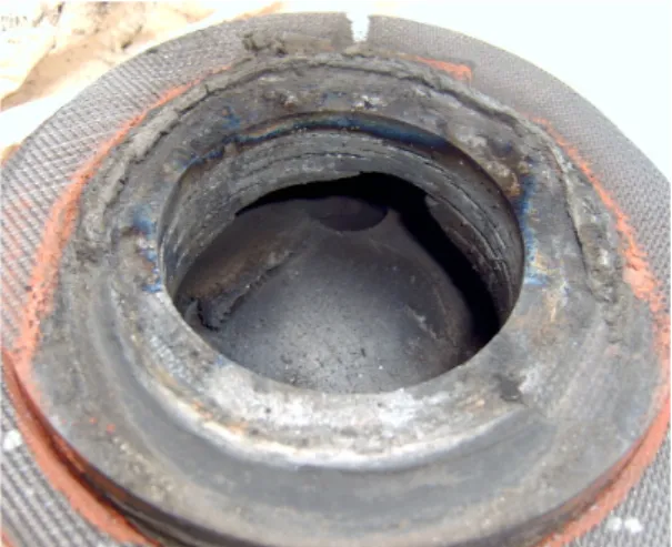
액적이 부딛혀 액상으로 만드는 역할을 충분히 하였음을 알 수 있다. Fig. 11은 시험 후 U-tube내부에 슬래그가 포집된 형상을 보여주고 있으며, Fig. 12는 포집된 슬래그를 꺼 내어 찍은 사진으로서 목적한 바대로 슬래그가 포집되었음을 보여준다.Figure 13은 U-tube추진기관을 해체한 후 시 험구간인 EPDM고무의 삭마량을 측정한 결과이 다. 연소시간이 짧은(27초) 0801, 0802 보다 연소 시간이 긴(54초) 0803, 0804의 경우에서 더 많은 삭마가 일어났음을 볼 수 있다. 특이한 점은 슬 래그가 덮여있던 노즐쪽보다 유속이 빠른 부위 들에서 삭마가 많이 진행되었음을 볼 수 있다.
Figure 13과 Fig. 14를 종합해보면 고무의 삭 마량은 접촉하는 매질의 종류보다는 유속에 의
Fig. 8 Photograph of propellant chamber after test
Fig. 9 Photograph of front ablative part(I) after test
Fig. 10 Photograph of front ablative part(II) after test
Fig. 11 Deposited slag in U-tube after test
Fig. 12 Separated Slag from U-tube
Fig. 13 Erosion shape of rubber insulator
Fig. 14 Mach-number contours in U-tube by CFD
존함을 알 수 있다. Fig. 14와 같은 해석과 연소 관내부의 유속해석 결과를 비교하여 연소관내열 재의 두께를 결정할 수 있는 중요한 시험 수단 을 개발한 것이다.
4. 결 론
연소가스에 포함된 Al
2
O3
가 연소관내에 침적 되었을 때 연소관내부의 고무내열재에 어떤 영 향을 미치는지 모사하기위한 방법으로 U-tube추 진기관을 고안하여 시험 평가하였다. U-tube 추 진기관은 연소시간/압력을 설계하려는 추진기관 과 같도록 할 수 있으며, 그 환경에서 고무의 열 반응을 측정할 수 있다. 측정한 결과 슬래그에 의한 고무삭마는 유속에 의한 영향보다 적음을 알 수 있었다.참 고 문 헌
1. J. C. Melcher, R. L. Burton, and H. Krier,
"Combustion of Aluminum Particles in Solid Rocket Motor Flows," AIAA 99-2630, 1999
2. William A. Dick and Michael T. Heath,
"WHOLE SYSTEM SIMULATION OF SOLID PROPELLANT ROCKETS," AIAA 2002-4345, 2002
3. Y. Fabignon, O.Orlandi, J. F. Trubert, D.
Lambert, and J. Dupays, "Combustion of Aluminum Particles in Solid Rocket Motors," AIAA 2003-4807, 2003
4. Vishal Srinivas and S. R. Chakravarthy,
"Computer Model of Aluminum
Agglomeration on the Burning Surface of a Composite Solid Propellant," AIAA 2005- 743, 2005
5. F.M. Najjar, L. Massa, R. Fiedler, A.
Haselbacher, B. Wasistho, S. Balachandar,
"Effects of Aluminum Propellant Loading and Size Distribution in BATES Motors: A Multiphysics Computational Analysis,"
AIAA 2005-3997, 2005
6. H. Wirzberger, Y. Macales and S. Yaniv,
"Prediction of Slag Formation in a Solid Rocket Motor," AIAA 2005-4488, 2005 7. T. L. Jackson, F. Najjar, and J. Buckmaster,
"New Aluminum Agglomeration Models and Their Use in Solid-Propellant-Rocket Simulations," JOURNAL OF PROPULSION AND POWER, Vol. 21, No. 5, September–
October 2005, pp.925-936
8. F. M. Najjar, J. P. Ferry, A. Haselbacher, and S. Balachandar, "Simulations of Solid-Propellant Rockets: Effects of Aluminum Droplet Size Distribution,"
JOURNAL OF SPACECRAFT AND ROCKETS, Vol. 43, No. 6, November–
December 2006, pp.1258-1270
9. Jay K. Sambamurthi, "Al
2
O3
Collection and Sizing from Solid Rocket Motor Plumes,"JOURNAL OF PROPULSION AND POWER Vol. 12, No. 3, May-June 1996, pp.598-604
10. Joseph H. Koo, Dave W.H. Ho, and Ofodike A. Ezekoye, "A Review of Numerical and Experimental Characterization of Thermal Protection Materials–Part I.
Numerical Modeling," AIAA 2006-4936, 2006