Innovative Geostationary Communication and Remote Sensing Mutli-purpose Satellite Program in Korea-COMS Program
Myung-Jin Baek1 and Jaewoo Park2
요 약
통신해양기상위성은 다목적 정지궤도위성으로서 Ka대역 통신탑재체, 기상센서 및 해양센서를 하나의 위성플랫폼에 탑 재한 복합위성이다. 본 논문에서는 한국정부의 자금으로 개발되는 첫번째 혁신적인 정지궤도 통신해양기상위성 프로그램 에 대해서 소개하고자 한다. 위성플랫폼은 아스트리움의 EUROSTAR 3000 통신위성을 기반으로 하고 있으며, 세 개의 다 른 탑재체를 효과적으로 수용하기 위하여 화성탐사선 Express를 일부 활용하였다. 세개의 탑재체 중 통신탑재체는 스위칭 다중빔 기술을 검증하고 광대역 멀티미디어 통신서비스를 시험하는데 목적이 있다. 기상센서임무는 고해상도 멀티분광 센서로 지속적으로 한반도 기상데이타를 산출하는데 있으며, 세계 최초의 정지궤도 해양센서는 한반도의 어류자원정보 및 장단기 해양정보의 모니터링을 목적으로 하고 있다. 통신임무와 원격탐사임무를 동시에 수행해야 하므로 위성체의 요 구사항은 매우 복잡하여 이를 만족시키기 위한 설계 및 조립/시험의 난이도는 매 우 높다고 할 수 있겠다.
ABSTRACT
COMS satellite is a multipurpose satellite in the geostationary orbit, which accommodates multiple payloads of the Ka band Satellite Communication Payload, Meteorological Imager, and Geostationary Ocean Color Imager into a single spacecraft platform. In this paper, Korea’s first innovative geostationary Communication, Ocean and Meteorological Satellite (COMS) program is introduced which is fully funded by Korean Government. The satellite platform is based on the Astrium EUROSTAR 3000 communication satellite, but creatively combined with MARS Express satellite platform to accommodate three different payloads efficiently for COMS. The goals of the Ka band satellite communication mission are to in-orbit verify the performances of advanced communication technologies and to experiment wide-band multi-media communication service. The Meteorological Imager mission is to continuously extract meteorological products with high resolution and multi-spectral imager, to detect special weather such as storm, flood, yellow sand, and to extract data on long-term change of sea surface temperature and cloud. The Geostationary Ocean Color Imager mission aims at monitoring of marine environments around Korean peninsula, production of fishery information (Chlorophyll, etc.), and monitoring of long-term/short-term change of marine ecosystem. The system design difficulties are in the different kinds of payload mission requirements of communication and remote sensing purposes and how to combine them into one to meet the overall satellite requirements. In this paper, Ka band communication payload system is more highlighted.
Key Words : COMS Satellite, Satellite communications, Meteorological mission, Ocean Monitoring
I. Introduction
COMS program is a national program of Korean government to develop and operate the COMS, a pure civilian satellite of practical-use for the compound missions of meteorological observation and ocean monitoring, and space test of experimentally developed communication payload, on the geostationary orbit. The target launch of COMS is scheduled in June of 2009.
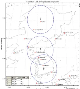
The mission orbit for COMS will be selected either 116.2° East or 128.2° East at the end of 2007.
The operational life of the COMS shall be no less than 7 years from the end of the IOT(In-Orbit-
Test) period, but the design life of the COMS shall be no less than 10 years. Unlike spin type weather satellite, COMS is 3-axis stabilization type spacecraft so that communication and remote sensing services can be accomplished at the same time. The spacecraft shall be designed to be compatible with at least the following launch vehicles and be compliant with all the constraints (configuration, weight, etc.) imposed by the launch vehicle agencies. The COMS shall be designed to survive all launch environments imposed by the launch vehicle, such as Arian launch vehicle families, Delta launch vehicle families, Atlas launch vehicle families, Proton launch vehicle, H-IIA launch vehicle and Sea-
* 1 COMS Program Office, Korea Aerospace Research Institute 45 Eoeun Dong, Yusung, Daejeon, KOREA 305-333 Email: [email protected] and [email protected]
* 2 Global Area Wireless Technology Research Group, Electronics Telecommunications Research Institute 161 Gajeong-dong, Yuseong-gu, Daejeon, 305-700, KOREA. Email: [email protected]
Launch vehicle.
The station-keeping accuracy of the COMS shall be ±0.05° in longitude and latitude of the nominal orbital location throughout the operational lifetime to provide good quality of communication services. The COMS will use the Ka band for the communication mission, and L-band, S-band frequencies for the meteorological and ocean data transmission. The S-band frequency, also, will be used for the transfer orbit operation to move the spacecraft into the mission geostationary orbit and for the normal operation in the mission orbit.
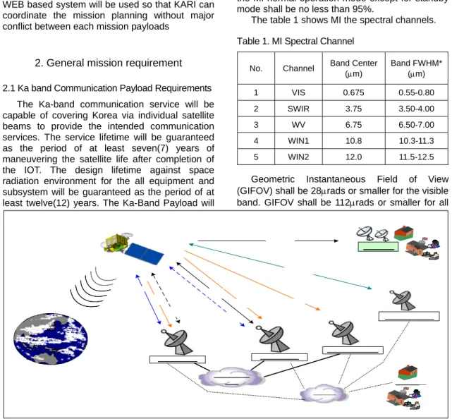
Figure 1 describes the COMS system architecture.
KARI is responsible for the satellite control, and each mission users(KMA, KORDI and ETRI) posses its own ground station. The COMS mission planning will be coordinated between each ground stations through dedicated line and WEB based system will be used so that KARI can coordinate the mission planning without major conflict between each mission payloads
2. General mission requirement
2.1 Ka band Communication Payload Requirements The Ka-band communication service will be capable of covering Korea via individual satellite beams to provide the intended communication services. The service lifetime will be guaranteed as the period of at least seven(7) years of maneuvering the satellite life after completion of the IOT. The design lifetime against space radiation environment for the all equipment and subsystem will be guaranteed as the period of at least twelve(12) years. The Ka-Band Payload will
provide multibeam functions for Korea. The Ka- Band Payload will provide the beam switching function for high speed multimedia services including the internet via satellite in the public communication network for all coverage. The Ka- Band Payload will provide a bent-pipe type function for communication services of natural disaster in government communication network of South Korea. The Ka-band payload system consists of one transponder subsystem and one antenna subsystem.
2.2 Meteorological Imager (MI) Requirements The operational life of the MI shall be no less than 7 years from the end of IOT. The MI shall be designed to be compatible with the COMS satellite storage requirement. The duty cycle of the MI normal operation mode except for standby mode shall be no less than 95%.
The table 1 shows MI the spectral channels.
Table 1. MI Spectral Channel
No. Channel Band Center (μm)
Band FWHM*
(μm)
1 VIS 0.675 0.55-0.80 2 SWIR 3.75 3.50-4.00 3 WV 6.75 6.50-7.00 4 WIN1 10.8 10.3-11.3 5 WIN2 12.0 11.5-12.5
Geometric Instantaneous Field of View (GIFOV) shall be 28μrads or smaller for the visible band. GIFOV shall be 112μrads or smaller for all
Figure 1. COMS System Architecture
IR bands.
2.3 Geostationary Ocean Color Imager (GOCI) Requirements
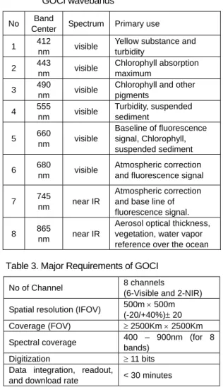
The spectral channels and their primary uses of GOCI are summarized in Table 2 and the major requirements of GOCI are specified in Table 3.
Table 2. Spectral characteristics and applications of GOCI wavebands
No Band
Center Spectrum Primary use 1 412
nm visible Yellow substance and turbidity
2 443
nm visible Chlorophyll absorption maximum
3 490
nm visible Chlorophyll and other pigments
4 555
nm visible Turbidity, suspended sediment
5 660
nm visible
Baseline of fluorescence signal, Chlorophyll, suspended sediment 6 680
nm visible Atmospheric correction and fluorescence signal
7 745
nm near IR
Atmospheric correction and base line of fluorescence signal.
8 865
nm near IR
Aerosol optical thickness, vegetation, water vapor reference over the ocean Table 3. Major Requirements of GOCI
No of Channel 8 channels (6-Visible and 2-NIR) Spatial resolution (IFOV) 500m × 500m
(-20/+40%)± 20 Coverage (FOV) ≥ 2500Km × 2500Km Spectral coverage 400 – 900nm (for 8
bands) Digitization ≥ 11 bits Data integration, readout,
and download rate < 30 minutes
The GOCI shall be operated on a fixed target area covering the Korean Seas and surrounding oceans. The duty cycle of GOCI requires 8 images during daytime and 2 images during night- time.
2.4 COMS Satellite Platform Requirements COMS satellite platform consists of several subsystems to support mission payloads. The Meteorological & Ocean Data Communication Subsystem (MODCS) shall comprise all signal
paths used for transmitting the meteorological and ocean data to MODAC and relaying the processed meteorological data to end users: raw Imager and Ocean Sensor Data (SD) including the MI/GOCI telemetry data and the attitude data for Image Navigation and Registration (INR); The TC&R subsystem shall provide the capability to communicate between ground station and spacecraft, to control and monitor the spacecraft so that it meets all performance requirements and is suitable for controlling the spacecraft at all expected attitude and attitude rate.
The Electrical Power Subsystem (EPS) shall generate, store, control and distribute electrical power as required by the various loads of satellite over all mission phases and the expected modes of operation. The Attitude and Orbit Control Subsystem (AOCS) shall determine and control the attitude of spacecraft during the spacecraft design life including the orbit control. Also, the performance of the Propulsion Subsystem(PS) shall be compatible with the attitude and orbit control requirements for the COMS satellite operation. The Thermal Control Subsystem(TCS) shall be designed to maintain all equipments and structures within the design temperature ranges under all the expected worst case conditions. The Structure and Mechanism Subsystem (SMS) shall provide the support, alignment and protection for the payloads and all spacecraft subsystem components. Finally, the FSW subsystem shall provide the capability to manage and control the overall spacecraft and payloads.
3. Coms satellite description
3.1 Overall Descriptions
The single-wing 2-panel solar array provides the electrical power to the satellite and allows keeping a free space for the MI radiant cooler field of view towards the North.
This asymmetrical configuration results in unusually large external disturbing torques due to solar pressure. However the length of the wing is kept small.
All the required fields of view are easily provided to the instruments, AOCS sensors and antennas, whatever the orbital position is in the specified range 116 E / 138 E. Adequate canting of the GOCI and of the Ka band Communication Payload antenna and sources will be accurately defined after freezing of the reference orbital position. The specified possible drift of the satellite on the orbit will be compensated through adequate pointing bias around pitch axis, which will remain well within the maximum biasing
capability. The solar array is free from any shadowing from the satellite main body on station.
+X Velocity +Z
Earth +Y
South
+X Velocity +Z
Earth +Y
South
Figure 2. COMS On-Orbit Configuration The platform electrical architecture provides an optimum performance and heritage of the Eurostar 3000 model. Centralized spacecraft computer and fully regulated power bus architectures have been employed based on ASTRIUM Eurostar in term of design robustness, Failure Detection Isolation and Recovery (FDIR) strategy, and operation ease. The Telemetry, Command and Ranging and Data Handling function has been designed to provide full compliance with a wide range of spacecraft control approaches (4 kbps telemetry, send-verify- execute sequence, shadow mode, large telemetry channels growth margin, etc). The data transmission between the central spacecraft computer and the other key units is performed via a serial 1553B digital data bus. This provides a very flexible and standard data transmission system, which can be easily adapted and tested to specific needs, with no hardware modification.
The interface of the spacecraft units to the data bus is performed either via the modular payload interface unit and the actuator drive electronics, or directly to the bus for some attitude control equipment’s or power subsystem regulator. Any unit connected on that bus can be switched off if it disturbs the bus itself.
A reliable and flexible Electrical Power Subsystem (EPS) provides the spacecraft units with a fully protected, double insulated 50 V power bus, fully regulated in sunlight and eclipse.
Maximum spacecraft robustness is provided: the power consumptions are strictly monitored by the on-board software & hardware protections. The COMS solar array is a standard Eurostar gallium arsenide 2-panel. The batteries are based on Li- Ion technology. The battery management in orbit is fully autonomous, automatic, safe and can be either modified or reconfigured by ground after a failure.
The COMS Attitude and Orbit Control System (AOCS) reuses to a very large extent the Eurostar
E3000 AOCS, as far a hardware and functional architecture are concerned. The Transfer and Acquisition phase is identical to Eurostar E3000 and is based on three axes stabilization. It allows simple operations of the spacecraft, without loss of safety. Station Keeping phases permit to maintain the spacecraft orbit inclination and eccentricity and are automatically managed with a high level of on board security. East/West maneuvers and pitch momentum off-loading are automatically managed by pulsed sequences in normal mode. Table 4 shows the summary table of the COMS satellite platform configuration and heritage which is a mostly dedicated adaptation of the Eurostar E3000 platform, that is the standard ASTRIUM platform developed for telecommuni- cation satellite and adapted for COMS.
3.2 Ka band Communication Payload
The payload provides the four 30/20 GHz RF channels for communications service and includes two antenna and on-board switching microwave transponder hardware in order to receive, switch, amplify, and transmit microwave signals within the required coverage area as fig 3.
Figure 3. Coverage of Ka-band Payload
The following types of transmission will be possible for any of the RF channels :
• Digital Transmission for the communication services against natural disaster:
- Single carrier wideband digital burst, for data rates upto 10 Mbps using TDM - M-ary PSK.
- QPSK(and/or BPSK) – TDM – TDMA digital two-way subscriber service with Hub control
station and remote terminals.
- PCM-QPSK-FDMA digital two-way subscriber service with VSAT user ground terminals.
- Communication type services such as prediction, prevention, recovery service for natural disaster.
• Digital Transmission for the high speed multimedia services:
- Single carrier narrowband digital burst, for data rates upto 155 Mbps using TDM – 8 PSK.
- QPSK(and/or BPSK) –TDMA digital two-way subscriber service with Hub control station and remote terminals.
- Multimedia type services such as Internet via satellite, remote medicine, distance learning etc.
• Analog Transmission
The performance requirements will be applied to the relevant services under the following conditions over the whole design lifetime unless otherwise specified:
• All operating conditions including the worst case antenna pointing and station- keeping maneuvers.
• All environmental conditions specified in the environmental conditions of paragraph
• With telemetry, command and tracking carriers present.
• For any combination of operating channels,
signal types, and over the operating RF channel bandwidth.
• During the eclipse period.
• For both fixed gain and automatic level control modes.
• In primary and redundancy modes of operation.
• Over the defined coverage area.
The payload is designed to prevent the occurrences of multipaction and the passive intermodulation products falling into the passband of receivers operating nearby and its redundancy switching is designed to minimize the communications outage when switching into redundant elements.
The payload system is met by the provision of double frequency conversion communications subsystem with intermediate frequency of S-band.
Figure 4 shows its block diagram. The main characteristics for switching are as followings;
• Each antenna comprises one single offset reflector assembly, two feed assemblies, interconnecting waveguides, deployable mechanisms, and restraint mechanisms.
• The antenna provides three beam coverage of South Korea, North Korea, and Dongbei area as backup.
• Each IF/RF channel filter isolates its transmission channel from other three S-band channels.
• The onboard switch is designed for multi-beam
Figure 4 Block Diagram of Ka-band Payload
switching. The onboard switch consists of microwave switch matrix(MSM) and digital control unit(DCU). MSM is provided for a means of beam switching between three uplink channels and three downlink channels.
• IF switching network provides the required interconnectivity between the primary and redundant MSM paths. Two IF switching networks is connected to the input and the output of the MSM, respectively.
• RF switching network provides the required interconnectivity between the operating channels and the primary and redundant amplifier paths. Two RF switching networks are connected to the input of channel amplifiers and another RF switching network is connected to the output of the TWTAs, respectively.
• Output multiplexer assembly is provided for a means of multiplexing the two RF channels and filtering the other two RF channels to the corresponding transmit antenna beams.
• Beacon assembly generates CW types of Ka- band beacon signal for testing Ka-band rain attenuation and for assisting the operation of ground antenna.
The performance of communication payload is expected as table 4.
Table 4 Performance of Ka-band payload Receive G/T 14.38dB/K
EIRP 59.99dBW G>T variation at normal
mode(overlife) 3.31dBp-p SFD variation at normal
mode(overlife) ± 2.67dB EIRP variation (overlife) 1.92dBp-p
3.3 Brief Description of MI and GOCI
The MI is a visible and infrared imaging radiometer that measures energy from Earth’s surface and atmosphere. It can be considered as the quantitative observer in a system to supply environmental data and data products. The MI for the COMS satellite is an off-the-shelf model of ITT’s Commercial Advanced Geo-Imager (CAGI).
The MI collects radiometric data in 5 spectral channels ranging from the visible to the thermal infrared, and useful for cloud and pollution detection, storm identification, fire location, cloud height measurement, water vapor wind vectors, ozone measurement, and surface and cloud top temperatures. It produces 10 bit digital numbers spanning the signal range of the channel linearly
proportional to the radiance at the input aperture.
The GOCI is the second core instrument of the COMS system. It acquires data in 8 visible wavebands with a spatial resolution no larger than 0.5 km over the Korean seas. The ocean data products that can be derived the measurements are mainly the chlorophyll concentration, the optical diffuse attenuation coefficient, the concentration of dissolved organic material or yellow substance, and the concentration of suspended particulates in the near-surface zone of the sea. In operational oceanography, satellite derived data products are used in conjunction with numerical models and in situ measurements to provide forecasting and now casting of the ocean state. Such information is of genuine interest for many categories of users.
The instrument will be designed and manufactured in ASTRIUM in house. The time required to acquire a full image, comprising the 16 slots in all 8 wavebands, is lower than 30 min, including image integration and readout time and filter wheel motion. The acquired data are directly transferred to the data communication system for immediate downlink in L Band to the ground segment.
4. Conclusion
In this paper, Korea’s first geostationary Communication, Ocean and Meteorological Satellte (COMS) program is introduced. COMS satellite is a hybrid satellite in the geostationary orbit, which accommodates multiple payloads of MI(Meteorological Imager), GOCI(Geostationary Ocean Color Imager), and the Ka band Satellite Communication Payload into a single spacecraft platform. The Ka-band payload will be used for testing Ka-band propagation, especially rain attenuation. The test will give the useful data for formulating the rain attenuation environment of the Korean peninsula and for defining VSAT terminals which will be used in multimedia communication. The MI mission is to continuously extract meteorological products with high resolution and multi-spectral imager, to detect special weather such as storm, flood, yellow sand, and to extract data on long-term change of sea surface temperature and cloud. The GOCI mission aims at monitoring of marine environ- ments around Korean peninsula, production of fishery information (Chlorophyll, etc.), and monitoring of long-term/short-term change of marine ecosystem. The goals of the Ka band satellite communication mission are to in-orbit verify the performances of advanced communica- tion technologies and to experiment wide-band multi-media communication service.
Acknowledgement
This work was partly supported by MOST for COMS Development Program and, also partly supported by IT R&D Program of MIC/IITA[2007- S301-03 Development of Satellite Communication System for COMS].
REFERENCE
[1] KARI, Request for Proposal for the Communication, Ocean and Meteorological Satellite(COMS) of Korea, 2004
[2] Feasibility Study on the Development of Communication Broadcasting and Meteorolo- gical Satellite, 2002.
[3] COMS Kickoff Meeting, EADS Astrium, 2005 [4] COMS System Requirement Data Packages,
EADS Astrium, 2005.
[5] COMS Critical Design Review Data Package, ASTRIUM SAS, 2007
[6] Final Design Review Data Packages of Ka- band Payload, ETRI, 2006.
저 자 백 명 진(Myung-Jin Baek)
1984년 2월: 한양대학교 기계 공학과 졸업 1987년 6월: Drexel Univ.
기계공학과 석사 1992년 10월: Drexel Univ.
기계공학과 박사 1993년 3월∼현재: 한국항공 우주연구원 통신해양기상위 성 책임연구원 재직
<관심분야> 자동제어공학, 인공위성시스템 개발
박 재 우(Jae Woo Park) 정회원 1990 년 2 월:한국전자통신
연구소
위성관제시스템 연구원 1997 년 7 월:러시아 과학 아카데미 우주연구소
박사
2000 년 4 월~현재:
한국전자통신연구원 통신위성시스템연구팀 책임연구원
< 관 심 분 야 > 위 성 임 무 분 석 , 위 성 체 시 스 템 설 계