* Dept. of Computer Engineering, Kwangwoon University, Seoul, Korea
※ This research has been supported by Nano IP/SoC Promotion Group and the Research Grant of Kwangwoon University in 2007.
An adaptive MAC protocol exploiting multiple paths in wireless mesh networks
Hyungkeun Lee
*, Joonhwan Yi
*([email protected], [email protected])
ABSTRACT
In recent years, the wireless mesh network (WMN) has been an emerging technology to provide Internet access to fixed and mobile wireless devices. The main goal of this paper is the design and simulation of a new MAC protocol based on the multi-path routing information for wireless mesh networks. The information about multiple paths discovered in the network layer is exploited by the MAC layer in order to forward a frame over the best hop out of multiple hop choices. The performance of our approach is compared with conventional 802.11 MAC through the simulation. The results show that our scheme exhibits a significantly better performance rather than conventional 802.11 MAC protocol in terms of packet overhead, end-to-end throughput and delay.
Key words : wireless mesh networks, cross-layer design, MAC protocol, multi-path routing
Ⅰ. Introduction
Wireless mesh networks (WMNs) appear as a promising technology to offer broadband wireless access to the Internet. Wireless mesh networks consist of gateways, mesh routers and mesh clients. Each node in such a network operates not only as an endpoint but also as a router that has the functionality to forward data over the next hop while maintaining route information. Wireless mesh networks are self-organized and self-configured in dynamic fashion where mesh routers self organize themselves in order to form a wireless backbone.
This feature brings many advantages to WMNs such as low installation cost, easy network maintenance, robustness, and reliable service coverage [1].
WMNs are able to provide Internet access to mesh
clients by means of standard radio interfaces.
Therefore, the delivery of data between two nodes is much more complex and challenging in WMNs.
For successful communications in such networks, a routing protocol should deal with the typical characteristics, such as limited bandwidth, high error rate, limited power capacity and node mobility. In this paper, we address a cross-layer technique between the MAC layer and routing layer and develop an adaptive MAC protocol that exploits such an interaction.
In WMNs, the state of a link between two mesh
routers is governed by the channel impairments
such as the interference plus noise and the fading
at the receiver. The channel impairments could be
time-varying, and significant changes in fading and
interference levels may lead to a transient link
failure. This link failure is often sufficient for
routing and transport protocols to react, which
causes operational inefficiencies. Therefore, there is
a need to devise an adaptive mechanism that can
tolerate this type of link failure at short time
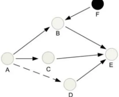
scales. Furthermore, intermediate mesh routers shared by others may cause data transmission to defer or even fail, called link blocking. The effect of link blocking as well as link failure can be alleviated by forwarding frames via an alternative path reaching the destination. An example is shown in Figure 1. The routing protocol decides a transmission path between mesh routers A and E, while the mesh router B is being accessed by another mesh router F and the link, A-D, is temporally broken due to the high level of fading.
The transmission via the B or D mesh routers leads to transmission retries, wasting bandwidth, deferring transmission and increasing delay. An improved approach would be choosing the next hop, A-C, on an alternate possible path, A-C-E, by the cross-layer coordination between the routing and MAC layers.
Fig. 1. MAC protocol based on path-diversity routing
We present a new approach called anycasting [2], where multiple route information is provided to the MAC layer which is in charge of the decision on which link to forward the frame and the MAC layer must take advantage of a multiple path routing protocol. Typically, the routing protocol in the network layer decides one route out of the several paths for data forwarding, and then the MAC layer is responsible to deliver frames to the next hop along the decided route. However, let the network protocol compute multiple routing paths from the source and also from the intermediate routers to the destination. A better approach in the MAC layer is to decide the next hop among the multiple next hops by the link status. This MAC protocol based on the link status improves
performance, requiring some coordination between the routing and MAC layers [3]. The goal of this paper is to develop a cross-layer technique of the MAC layer, where multi-path routes are discovered in the routing protocol and the virtual carrier sense mechanism is improved in the MAC protocol.
Our routing protocol is based on the Signal Power Adaptive Fast Rerouting (SPAFAR) protocol [4]
which consists of two phases namely the route discovery phase and the route maintenance phase.
We modify a route discovery algorithm to find multiple paths at the source and the intermediate nodes. While such a MAC layer protocol can be designed in many ways, a proper way to design is an extension of the widely-used IEEE 802.11 [5]
MAC protocol.
The remainder of this paper is organized as follows. Section 2 presents the multi-path routing protocol based on SPAFAR and the overview of the 802.11 MAC protocol. The scheme of the proposed MAC layer in ad hoc networks is described in Section 3. In Section 4, the simulation results and performance comparison is shown.
Finally, concluding remarks are given in Section 5.
Ⅱ. Related Work
In this section, we start by briefly reviewing the multipath routing protocol to design an adaptive MAC protocol based on path-diversity routing information. Then, the 802.11 distributed coordination function (DCF), the MAC layer functionality, is briefly described.
2.1 Multipath Routing Protocol
Each node of ad hoc networks keeps a Neighbor_Table (NT) which has an updated list of its neighbors. The NT can be easily obtained by periodic broadcasts of the beacon. A node is deleted from the NT, when that node moves out of the transmission range or ceases operation.
Likewise, a new node is added to the NT, when it
enters the transmission range of the node under
consideration. Each node also keeps a
Routing_Table (RT) which has an updated list of
all the possible routes to all the potential
destinations. The RT is constructed by an
on-demand routing algorithm. Each element in the RT is a five-tuple of the form <src, dst, nxt1, cnt1, nxt2, cnt2, …>. The src and dst fields contain the unique addresses of the source and the destination node, respectively. The nxt field contains the address of the neighbor node to which data packets need to be forwarded. The cnt field contains the number of intermediate nodes from the source to the destination node on this route.
The SPAFAR protocol consists of two distinct phases, the route discovery and maintenance phases. We modify the route discovery mechanism to find multiple paths from a source and intermediate nodes to a desired destination node.
When a source wants to send data to a destination and its RT does not have route information to the destination, the source initiates the route discovery mechanism to find all possible paths to the destination. The route discovery mechanism is based on request-reply operations.
An R_Request packet is used for the request operation from the source node and carries <src, dst, rq_id, int_node, hop_cnt> information. The src and dst fields contain the addresses of the source and destination respectively. The rq_id field contains a unique identifying number generated locally to distinguish it from the other R_Request packets. The int_node field keeps a sequence of all the intermediate nodes from the source to destination, while the packet traverses to the destination. The hop_cnt field contains the number of intermediate nodes between the source and destination. In response to a R_Request packet, a R_Reply packet is sent from the destination node and carries <src, dst, rq_id, int_node, hop_cnt>
information. The source field contains the address of the node that sends the R_Reply packet. The destination field contains the address of the node which sent the R_Request packet. The fields, rq_id, int_node and hop_cnt, contain the packet identifier, sequence of nodes from the destination to the source and the number of hops, respectively.
The int_node field in the R_Reply packet is the reverse of that received in the R_Request packet.
z
Processing a R_Request : when a source wants to find multiple disjoint paths to a destination, the source broadcasts a R_Request packet to its
neighbors. When a node receives a R_Request packet, the following procedures are invoked.
z
Processing a R_Reply : Upon receiving a R_Request packet, the destination sends a R_Reply packet which corresponds to the received R_Request packet along int nodes in the R_Reply packet. When a node receives the R_Reply packet, the following procedure is invoked.
Based on the procedures above, multiple R_Request packets which are not discarded at nodes are guaranteed to reach the destination along a loop free sequence of nodes. Also multiple R_Reply packets are sent back to the source, if there are multiple paths between the source and destination nodes. Other parts of the route discovery phase and the route maintenance phase are utilized without any modifications. The detailed operation of the SPAFAR routing protocol is described in [4].
2.2 IEEE 802.11 DCF
The 802.11 MAC protocol defines two modes of
operation: Distributed Coordination Function (DCF)
which allows contention access for wireless media
and Point Coordination function (PCF) which
requires centralized access points. DCF uses a
channel access mechanism known as Carrier Sense
Multiple Access with Collision Avoidance
(CSMA/CA) as shown in Figure 2. Carrier sense is
performed by a combination of physical and virtual
carrier sense mechanisms. A node with packets to
transmit first senses the medium. If the medium is
idle for at least a certain period, DIFS, it will
immediately request the channel by sending a
control frame, Request to Send (RTS), to the
receiver node. If the receiver correctly receives
RTS, it will reply with a short control frame Clear
to Send (CTS). Once the transmitter receives CTS,
it will start to transfer a data frame. After the
successful reception of the frame, the receiver
sends an ACK to the transmitter. The exchange of
RTS/CTS prior to the actual data transmission
reduces the collision probability in a distributed
manner and copes with the hidden terminal
problem [5].
Fig. 2. Operation of 802.11 DCF
Ⅲ. Next-Hop Selection Based on Path-Diversity Information
The MAC layer can acquire the information about possible next-hop options from the upper layer, and its responsibility is to transmit frames to any one of these receivers successfully. The modification of 802.11 DCF still uses the CSMA/CA algorithm, but takes advantage of multiple receivers with the goal to transmit the frame to any one of them successfully. The routing protocol computes multiple routes between the source and destination.
At each hop, the routing layer passes on the multiple next hop information to the MAC layer.
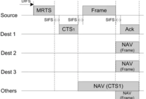
The transmitter now broadcasts the RTS to these multiple next hops, which is referred to the multicast RTS as MRTS; it contains all the MAC addresses of next hop receivers. Because of practical implementation considerations such as RTS frame size and time delay, we limit the number of next hops to use to a maximum of three as shown in Figure 3 and Figure 4.
Fig. 3. Case of the first mesh router's response in the next-hop selection
Fig. 4. Case of the third mesh router's response in the next-hop selection
By positioning the addresses of three next hops onto the MRTS frame, we can assign a priority order to each next hop. The priority can come from the routing or any lower layer. In the case that a shorter path to the destination gets higher priority, the routing decision in the network layer is the crucial metric for the priority. On the other hand, the information from the physical layer can be utilized to decide the priority based on the next hop that has less number of packets waiting in the queue or that has better signal strength. A combination of the above can also be used.
When the MRTS frame is broadcast to all the neighbors and all intended receivers receive the MRTS packet, the receivers respond by CTS.
These CTS transmissions are intentionally delayed in time in the order of their priorities. The first receiver in the priority order tries to transmit the CTS after an SIFS if possible as shown in Figure 3. The second transmits the CTS after the period equal to the time to transmit a CTS, an SIFS and a PIFS if there is no transmission on the channel from the transmitter due to the failure of the first CTS transmission. When the first and second receivers fail to transmit the CTS to the transmitter, the third receiver transmits the CTS after the period equal to the time to transmit a CTS, two SIFSs and two PIFSs as shown in Figure 4. CTS transmissions are separated by one PIFS period in order to avoid collisions.
When the transmitter receives the CTS from the
first receiver in the priority order, the transmitter
transmits the DATA frame after an SIFS interval
to the sender of this CTS, the first receiver, as
shown in Figure 3. This ensures that other, lower
45 m
45 m
priority receivers hear the DATA before they send CTS and suppress any further CTS transmissions.
If the first and second receivers fail to transmit the CTS and the third receiver transmits the CTS, the transmitter finally forwards the DATA frame to the third receiver as shown in Figure 4.
All the receivers hearing a CTS from any intended receiver then set their NAV until the end the ACK instance. These receivers successfully sense the carrier with the exact value of NAV. Any receiver hearing only the MRTS may not set the NAV value with the MRTS, because the total time to deliver a DATA frame cannot be guaranteed. In [2], any other receivers that hear the MRTS (exposed routers), set their NAV for the entire duration mentioned in the MRTS packet. This duration depends upon the number of receivers (which is a maximum of three in Figure 3 and Figure 4) to which MRTS is being sent. In this paper, however, the value of NAV is set by CTS and DATA not MRTS, since the size and transmission time of control frames such as the MRTSs and CTSs are relatively are smaller than the DATA frames. The any other receivers that received the MRTS may also try to sense the carrier under the assumption that the first receiver received the DATA frame successfully.
Furthermore, the usage of both MRTS and CTS help any other receivers identify themselves the exposed routers or hidden routers, and the any other receivers hearing only the MRTS set the NAV value by the DATA frame.
If none of the CTSs are received successfully, the transmitter goes into a random backoff and then retries again with the same receivers as in 802.11 DCF. Note that the protocol reduces to the DCF operation when there is only one next hop receiver, and that when multiple next hops are indeed available and the CTS from the highest priority receiver is received successfully, this would be exactly the same as 802.11.
Ⅳ. Performance Evaluation
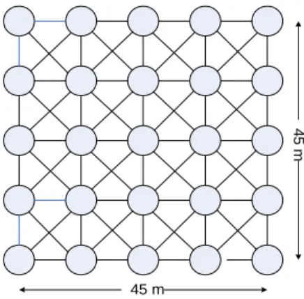
For the simulation, the grid topology consisting of 25 mesh routers over a 45m
☓45m terrain was
considered. The maximum transmission power range is assumed to be 15m between nodes. Mesh routers were placed with a regular distance within the fixed-size physical terrain. The source and destination routers are selected at the middle locations of leftmost and rightmost columns, respectively, during the whole simulation.
Fig. 5. Network topology for simulation
The traffic model used between source and destination routers is a constant bit rate (CBR) traffic with a rate of 20 frames/sec (512 byte for a frame). Other two more traffic were generated from leftmost routers to rightmost routers with CBR of 10 frames/sec in the simulation. Simulation parameters are shown in Table 1.
Tab. 1 .Simulation Parameters
Parameters Values
Network Size 45m
☓45m
Transmission Range 15m
Frame Size 512 byte
Traffic Model CBR
No. of Traffic 3
The priority is decided according to the number of hops from the source and the destination. The next hop link on the shortest path has highest priority.
In order to consider the temporal changes of link
status, a link is marked down and the next
shortest alternative is used when the number of
transmissions on the link exceeds the maximum
retry count. A route error is generated only when
all alternatives are exhausted.
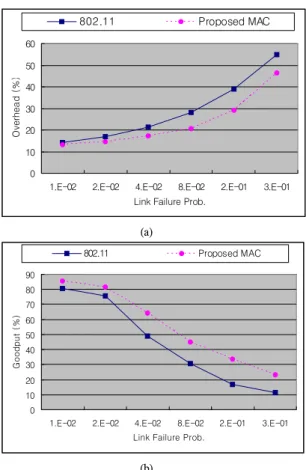
0 10 20 30 40 50 60
1.E-02 2.E-02 4.E-02 8.E-02 2.E-01 3.E-01 Link Failure Prob.
Overhead (%)
802.11 Proposed MAC
(a)
0 10 20 30 40 50 60 70 80 90
1.E-02 2.E-02 4.E-02 8.E-02 2.E-01 3.E-01 Link Failure Prob.
Goodput (%)
802.11 Proposed MAC