Vol.21, No.2, (2019), pp.15~21 https://doi.org/10.9714/psac.2019.21.2.015
```
1. INTRODUCTION
Mine water treatment is required accompanied with mine exploration. Mine water is groundwater from the site where underground resources are mined or from the abandoned mine [1]. Because mine water contains heavy metal ions harmful to the human body, it is necessary to remove them from mine water.
The mechanism of generation of the mine water is described by Equation (1). Here, the generation mechanism of mine water containing iron ion, one of the heavy metal ions, is shown.
2FeS2 + 7O2 + 2H2O → 2Fe2+ + 4SO42- + 4H+ (1)
Iron contained minerals (FeS2) react with oxygen in the air and water. And then, iron ions and hydrogen ions are dissolved into mine water, and acidic mine water is generated. Moreover, the acidic condition promotes the dissolution of heavy metals from the minerals [2]. Thus, sustainable treatment system of mine water is required.
Conventional mine water treatment methods are coagulation sedimentation, precipitation by neutralization and sand filtration. TABLE Ⅰ shows the advantages and disadvantages of each method. Coagulation sedimentation method has an advantage of efficient precipitation, but it has disadvantages of high cost and the necessity of sludge disposal. On the other hand, sand filtration method has an advantage of low power consumption, but filter materials need to be replaced periodically. Based on these, a sustainable treatment system of mine water with energy saving and minimized chemical additives are required.
Various kinds of heavy metals are contained in the mine water. In many cases, mine water contains highly-concentrated iron ions about 10 to 12000 mg/L [3].
Therefore, a study on iron removal method is important among the heavy metals.
We propose the system combining air oxidation method using solid catalyst modified magnetite and magnetic separation method. The conceptual diagram of the system is shown in Fig. 1.
This system consists of the precipitation process and the separation process. The precipitation process is utilizing air
TABLE Ⅰ
COMPARISON OF EXISTING MINE WATER PURIFICATION METHODS. Advantages Disadvantages Coagulation
sedimentation / Neutralization
Efficient precipitation
- High cost
- Necessity of additives - Necessity of sludge disposal
Sand filtration Low power consumption
Necessity of periodical replacement of filter material
Fig. 1. The proposed system of mine water treatment.
Fundamental study on sustainable treatment system of mine water using magnetized solid catalyst
Chisato Mukuta, and Yoko Akiyama*
Graduate School of Engineering, Osaka University, Osaka, Japan
(Received 21 January 2019; revised or reviewed 15 March 2019; accepted 16 March 2019)
Abstract
In the mine exploration sites, sustainable treatment system of mine water with energy saving and minimized chemical additives is required. Since most of the mine water contains highly-concentrated ferrous ion, it is necessary to study on the removal method of iron ions. We propose the system consisting of two processes; precipitation process by air oxidation using solid catalyst-modified magnetite and separation process combining gravitational sedimentation and magnetic separation using a permanent magnet.
Firstly, in the precipitation process (a former process of the system), we succeeded to prepare solid catalyst-modified magnetite. Air oxidation using solid catalyst-modified magnetite using Fe2(SO4)3 as a starting material showed high iron removal capability.
Secondly, in the separation process (latter process of the system), solid catalyst-modified magnetite using Fe2(SO4)3 as a starting material can be separated by a superconducting bulk magnet and a permanent magnet.
Keywords: mine water, iron removal, solid catalyst, modified magnet, air oxidation, magnetic separation, permanent magnet
* Corresponding author: [email protected]
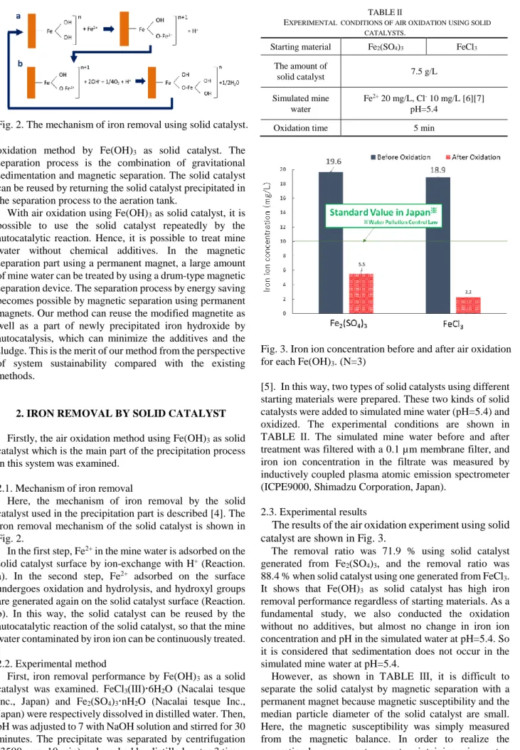
Fig. 2. The mechanism of iron removal using solid catalyst.
oxidation method by Fe(OH)3 as solid catalyst. The separation process is the combination of gravitational sedimentation and magnetic separation. The solid catalyst can be reused by returning the solid catalyst precipitated in the separation process to the aeration tank.
With air oxidation using Fe(OH)3 as solid catalyst, it is possible to use the solid catalyst repeatedly by the autocatalytic reaction. Hence, it is possible to treat mine water without chemical additives. In the magnetic separation part using a permanent magnet, a large amount of mine water can be treated by using a drum-type magnetic separation device. The separation process by energy saving becomes possible by magnetic separation using permanent magnets. Our method can reuse the modified magnetite as well as a part of newly precipitated iron hydroxide by autocatalysis, which can minimize the additives and the sludge. This is the merit of our method from the perspective of system sustainability compared with the existing methods.
2. IRON REMOVAL BY SOLID CATALYST Firstly, the air oxidation method using Fe(OH)3 as solid catalyst which is the main part of the precipitation process in this system was examined.
2.1. Mechanism of iron removal
Here, the mechanism of iron removal by the solid catalyst used in the precipitation part is described [4]. The iron removal mechanism of the solid catalyst is shown in Fig. 2.
In the first step, Fe2+ in the mine water is adsorbed on the solid catalyst surface by ion-exchange with H+ (Reaction.
a). In the second step, Fe2+ adsorbed on the surface undergoes oxidation and hydrolysis, and hydroxyl groups are generated again on the solid catalyst surface (Reaction.
b). In this way, the solid catalyst can be reused by the autocatalytic reaction of the solid catalyst, so that the mine water contaminated by iron ion can be continuously treated.
2.2. Experimental method
First, iron removal performance by Fe(OH)3 as a solid catalyst was examined. FeCl3(Ⅲ)6H2O (Nacalai tesque Inc., Japan) and Fe2(SO4)3nH2O (Nacalai tesque Inc., Japan) were respectively dissolved in distilled water. Then, pH was adjusted to 7 with NaOH solution and stirred for 30 minutes. The precipitate was separated by centrifugation (3500 rpm, 10 min) and washed by distilled water 3 times
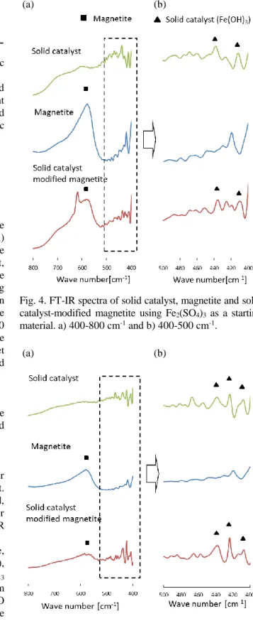
TABLEⅡ
EXPERIMENTAL CONDITIONS OF AIR OXIDATION USING SOLID CATALYSTS.
Starting material Fe2(SO4)3 FeCl3 The amount of
solid catalyst 7.5 g/L
Simulated mine water
Fe2+ 20 mg/L, Cl- 10 mg/L [6][7]
pH=5.4
Oxidation time 5 min
Fig. 3. Iron ion concentration before and after air oxidation for each Fe(OH)3. (N=3)
[5]. In this way, two types of solid catalysts using different starting materials were prepared. These two kinds of solid catalysts were added to simulated mine water (pH=5.4) and oxidized. The experimental conditions are shown in TABLE Ⅱ. The simulated mine water before and after treatment was filtered with a 0.1 µm membrane filter, and iron ion concentration in the filtrate was measured by inductively coupled plasma atomic emission spectrometer (ICPE9000, Shimadzu Corporation, Japan).
2.3. Experimental results
The results of the air oxidation experiment using solid catalyst are shown in Fig. 3.
The removal ratio was 71.9 % using solid catalyst generated from Fe2(SO4)3, and the removal ratio was 88.4 % when solid catalyst using one generated from FeCl3. It shows that Fe(OH)3 as solid catalyst has high iron removal performance regardless of starting materials. As a fundamental study, we also conducted the oxidation without no additives, but almost no change in iron ion concentration and pH in the simulated water at pH=5.4. So it is considered that sedimentation does not occur in the simulated mine water at pH=5.4.
However, as shown in TABLE Ⅲ, it is difficult to separate the solid catalyst by magnetic separation with a permanent magnet because magnetic susceptibility and the median particle diameter of the solid catalyst are small.
Here, the magnetic susceptibility was simply measured from the magnetic balance. In order to realize the separation by permanent magnet maintaining mine water
TABLEⅢ
MAGNETIC SUSCEPTIBILITY AND PARTICLE SIZE OF SOLID CATALYST. Fe2(SO4)3 FeCl3 Magnetic
susceptibility[-] 2.8×10⁻⁵ 4.4×10⁻⁵
Median particle
diameter [µm] 13.2 14.9
Minimum particle
diameter [µm] 6.7 5.9
treatment capacity, it is necessary to increase the magnetic susceptibility and particle size.
Thus, we focused on the magnetic susceptibility of solid catalyst and examined a method to increase the apparent magnetic susceptibility by preparing solid catalyst-modified magnetite, in which the ferromagnetic material is coated with a solid catalyst.
3. PREPARATION OF SOLID CATALYST-MODIFIED MAGNETITE 3.1. Preparation method
Solid catalyst-modified magnetite was prepared by the following method. FeCl36H2O (Nacalai tesque, Inc, Japan) and Fe2(SO4)3nH2O (Nacalai tesque, Inc, Japan) were respectively dissolved in distilled water. After that, magnetite was added so that the mass ratio of magnetite (Primary particle size 100 nm, Sample 2, MITSUI Mining
& Smelting Co., Japan) to Fe(OH)3 was 1:1, and then ultrasonic dispersion was carried out for 10 minutes. The pH was adjusted to 7 with NaOH solution and stirred for 30 minutes to obtain solid catalyst-modified magnetite. The objective product was separated by a permanent magnet and washed with distilled water 3 times to prepare solid catalyst-modified magnetite.
3.2. Evaluation of solid catalyst-modified magnetite FT-IR and weight measurements of the products were carried out, in order to confirm that magnetite was modified with the solid catalyst.
3.2.1. FT-IR measurement
FT-IR measurement was performed to confirm whether the magnetite surface is modified by the solid catalyst.
Initially, we considered to use XRD for analytical method, but peaks could not be detected because of the poor crystallinity of the prepared solid catalysts. Thus, FT-IR was used as an analytical method in this experiment.
In FT-IR measurement, 5 types of products; magnetite, solid catalyst (Fe2(SO4)3 or FeCl3 as a starting material), and solid catalyst-modified magnetite (Fe2(SO4)3 or FeCl3
as a starting material) were analyzed. Fourier Transform Infrared Spectrometer (FT/IR-470 Plus, JASCO Corporation, Japan) was used for the measurement. The measurement was carried out by potassium bromide disk method (wavelength number range: 399-4000 cm-1, cumulative number: 256). The FT-IR spectra are shown in Fig. 4 and 5.
From Fig.4 and 5, solid catalyst-modified magnetite (Fe2(SO4)3 or FeCl3 as a starting material) separated by permanent magnet showed the peaks of both solid catalyst and magnetite. This shows the magnetite was modified with solid catalyst.
(a) (b)
Fig. 4. FT-IR spectra of solid catalyst, magnetite and solid catalyst-modified magnetite using Fe2(SO4)3 as a starting material. a) 400-800 cm-1 and b) 400-500 cm-1.
(a) (b)
Fig. 5. FT-IR spectra of solid catalyst, magnetite and solid catalyst-modified magnetite using FeCl3 as a starting material. a) 400-800 cm-1 and b) 400-500 cm-1.
TABLE Ⅳ
THE RESULT OF WEIGHT MEASUREMENT.
Starting material Fe2(SO4)3 FeCl3
Before modification
Fe(OH)3 1.21 g 1.51 g
Fe3O4 1.50 g
After modification
Attracted to
magnet 2.66 g 3.35 g
Not attracted to
the magnet 0.03 g 0.04 g
3.2.2. Weight measurement
Weights of magnetite, solid catalyst (Fe2(SO4)3 or FeCl3
as a starting material), and solid catalyst-modified magnetite (Fe2(SO4)3 or FeCl3 as a starting material) was also measured to confirm quantitatively whether the magnetite was modified with the solid catalyst.
In the weight measurement, the weight of the particles attracted and not attracted the permanent magnet (maximum surface magnetic flux density 0.4 T, length 2.5 cm, width 2.5 cm, height 1.2 cm) were measured, and modification of magnetite by solid catalyst was evaluated.
The results of the weight measurement are shown in TABLE Ⅳ.
About 100 % of solid catalyst-modified magnetite attracted to the magnet. The result of FT-IR measurement and weight measurement show that we succeeded to prepare the solid catalyst-modified magnetite.
3.3. The properties of solid catalyst-modified magnetite The particle size distribution of the prepared solid catalyst-modified magnetite was measured using laser scattering particle size distribution analyzer (LA-920, HORIBA, Ltd., Japan). The median diameter measured by the particle size distribution measurement is shown in TABLE Ⅴ. The particle size of solid catalyst-modified magnetite for Fe2(SO4)3 and FeCl3 as a starting material were respectively about 39.8 µm, 41.0 µm. In addition, the particle size of solid catalyst-modified magnetite is larger than that of the pure solid catalyst. In addition, the primary particle diameter of magnetite is 100 nm. It is considered that the prepared solid catalyst-modified magnetite is not consisting of single magnetite particle with solid catalyst coating, but the mixture of several solid catalyst particles and magnetite particles.
4. IRON REMOVAL BY SOLID CATALYST-MODIFIED MAGNETITE
4.1. Experimental method TABLE Ⅴ THE RESULT OF PARTICLE SIZE.
Fe2(SO4)3 FeCl3
Solid catalyst 13.2 µm 14.9µm
Magnetite 2.6 µm
Solid catalyst-modified
magnetite 39.8 µm 41.0 µm
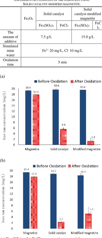
TABLE Ⅵ
EXPERIMENTAL CONDITION OF AIR OXIDATION USING
SOLID CATALYST-MODIFIED MAGNETITE.
Fe3O4
Solid catalyst
Solid catalyst-modified
magnetite Fe2(SO4)3 FeCl3 Fe2(SO4)3 FeC
l3
The amount of
additive
7.5 g/L 15.0 g/L
Simulated mine water
Fe2+ 20 mg/L, Cl- 10 mg/L Oxidation
time 5 min
(a)
(b)
(a) Fe2(SO4)3, (b) FeCl3 as a starting material.
Fig. 6. Iron ion concentration before and after air oxidation using pure magnetite, pure solid catalyst and solid catalyst-modified magnetite. (N=3, N=4 for only modified magnetite using FeCl3.)
Air oxidation experiment was carried out using two types of solid catalyst-modified magnetite (Fe2(SO4)3 or FeCl3 as a starting material) in order to examine whether the prepared solid catalyst-modified magnetite has iron removal capability. Air oxidation using pure magnetite was also carried out as the reference, and the results of air oxidation using two types of pure solid catalysts (Fe2(SO4)3
or FeCl3 as a starting material) was used for comparison. In the same method with Chapter 2, simulated mine water was adjusted to 20 mg/L of Fe2+[6] and 10 mg/L of Cl- [7] using FeSO4(Ⅱ)7H2O ((Nacalai tesque, Inc., Japan) and NaCl (Kishida Chemical Co., Japan). The experimental conditions are shown in TABLE Ⅵ.
The simulated mine water before and aftertreatment was filtered under reduced pressure with 0.1µm membrane filter, and then iron ion concentration in the filtrate was measured by ICP-AES.
4.2. Experimental results
The result of air oxidation experiment using solid catalyst-modified magnetite is shown in Fig.6. The removal ratio was shown in TABLE Ⅶ.
Air oxidation using solid catalyst-modified magnetite (Fe2(SO4)3 or FeCl3 as a starting material) showed both iron removal capability, whereas air oxidation using pure magnetite did not show iron removal capability. This result shows that the solid catalyst on the magnetite surface also has iron removal capability.
4.3. Discussions
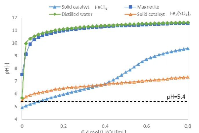
In the comparison of the oxidation reaction, the solid catalyst using FeCl3 as a starting material showed higher iron removal capability than that using Fe2(SO4)3. In order to investigate the reason why the iron removal capability differs depending on the starting material, potentiometric titration was carried out. It is possible to quantify released and adsorbed amount of H+ from the solid catalyst by potentiometric titration. 0.4 mol/L KOH solution was added to a suspension of 1.0 g of the solid catalyst in 100 mL of distilled water, and the change in pH was monitored.
Titration experiments were conducted on four conditions;
distilled water, pure magnetite suspension, pure solid catalyst suspension (Fe2(SO4)3 or FeCl3 as a starting material). The results are shown in Fig.7.
At the pH of the simulated mine water (pH=5.4), the solid catalyst using FeCl3 as a starting material showed higher pH drop relative to the blank curve (distilled water), compared with that using Fe2(SO4)3. It is considered that the solid catalyst using FeCl3 as a starting material has a higher buffer capacity than that using Fe2(SO4)3. This suggests that the solid catalyst using FeCl3 as a starting material released more H+ than that using Fe2(SO4)3. It is considered that Fe2+ was efficiently removed from the simulated mine water by ion exchange of H+ and Fe2+ in simulated mine water using FeCl3. It indicates that the solid catalyst using FeCl3 as a starting material shows higher iron removal capability than that using Fe2(SO4)3.
Fig. 7. Potentiometric titration of distilled water, pure magnetite and pure solid catalyst (Fe2(SO4)3 or FeCl3 as a starting material).
TABLE Ⅷ
pH CHANGE IN SOLID CATALYST AND SOLID CATALYST MODIFIED MAGNETITE TO SIMULATED MINE WATER.
Simulated mine water
FeCl3 Fe2(SO4)3
Solid catalyst
Modified magnetite
Solid catalyst
Modified magnetite
5.37 4.51 4.96 5.42 6.06
Fig.7 also shows that the titration curve of magnetite and blank were almost the same. It indicates that magnetite has no buffering capacity. It indicates that iron removal capability by ion exchange cannot occur with magnetite.
On the other hand, in the comparison of the oxidation reaction using solid catalyst-modified magnetite shown in Fig.6 (a) and (b), the solid catalyst-modified magnetite using Fe2(SO4)3 as a starting material showed higher iron removal capability than that using FeCl3. This is considered because of pH change by the addition of solid catalyst-modified magnetite. It is reported that the oxidation reaction is promoted by an increase in pH [8].
TABLE Ⅷ shows the pH change of simulated mine water after addition of solid catalyst-modified magnetites. After the addition of the solid catalyst-modified magnetite, the pH in the case of using FeCl3 as a starting material was decreased, whereas that in the case of using Fe2(SO4)3 was increased. Because the pH in the case of Fe2(SO4)3 as a starting material (pH=6.06) is higher than that in FeCl3
(pH=4.96), oxidation reaction was promoted and iron removal capability was improved.
Fig. 6 shows that the iron removal capability of solid catalyst-modified magnetite using FeCl3 as a starting material was lower than that of the pure solid catalyst using FeCl3. This is considered because the surface hydroxyl group relating to solid catalyst activity was partly used for the bind with magnetite.
On the other hand, solid catalyst modified-magnetite using Fe2(SO4)3 as a starting material showed higher iron removal performance than that of the pure solid catalyst using Fe2(SO4)3. As same as the solid catalyst-modified magnetite using FeCl3 as a starting material, it is considered that the surface hydroxyl group was partly used for the bind TABLE Ⅶ
THE REMOVAL RATIO OF IRON ION USING MAGNETITE, SOLID CATALYST AND SOLID CATALYST-MODIFIED MAGNETITE.
Fe3O4 Solid catalyst Solid catalyst-modified magnetite Fe2(SO4)3
7.7 %
71.9 % 93.4 %
FeCl3 88.4 % 72.1 %
with magnetite. However, the pH increased up to about 6 by adding solid catalyst-modified magnetite to the simulated mine water. In the case of Fe2(SO4)3, it is considered that promotion of the oxidation reaction due to an increase in pH was a greater influence than that the surface hydroxyl group of the solid catalyst was used for binding of magnetite. Therefore, it is considered that the solid catalyst-modified magnetite using Fe2(SO4)3 as a starting material has higher iron removal capability than the solid catalyst using Fe2(SO4)3.
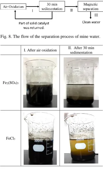
5. CONSIDERATION OF SEPARATION PROCESS In order to construct a mine water treatment system, it is necessary to consider a method for separating the solid catalyst-modified magnetite and oxidation product of iron ion from the suspension after the air oxidation. Fig.8 shows a flow chart starting from air oxidation process to the supply of clean water.
After air oxidation, as shown in Fig.8, we propose the method combining gravity sedimentation and magnetic separation to separate the solid catalyst-modified magnetite.
TABLE Ⅷ shows the state before and after sedimentation (Ⅰ) for 30 minutes after air oxidation. Fig.9. shows that most of the solid catalyst-modified magnetite was precipitated by 30 minutes sedimentation. Hence, the magnetic separation method is used for further separation of the solid catalyst-modified magnetite from the simulated mine water.
In this chapter, we examined the possibility of separation using a magnetic separation method.
5.1. Experimental method
As in Chapter 4, the air oxidation experiment was carried out using two types of solid catalyst-modified magnetite.
After air oxidation (Ⅰ), sedimentation was carried out for 30 minutes and the state after sedimentation (Ⅱ) was observed.
After the sedimentation for 30 minutes, the supernatant of the simulated mine water was sampled, and the solution (Ⅲ) was attracted to the superconducting bulk magnet or permanent magnet to carry out the batch type magnetic separation of the solid catalyst-modified magnetite. The maximum surface magnetic flux density of superconducting bulk magnet was 3.2 T and maximum at the separation area was about 2.5 T (3 mm above the cryostat). The superconducting bulk magnet consists of GdBaCuO bulk superconductor (Nippon Steel Co.), the shape is cylindrical with 60 mm in diameter and 20 mm in thickness. The superconducting bulk magnet was installed on the refrigerator core stage (CS) and cooled to a temperature to 30 K CS temperature using GM refrigerator (high-temperature superconducting bulk cooling system (Aisin Seiki Co., Ltd.)). On the other hand, the size of permanent magnet was 25 mm × 25 mm ×12 mm, maximum surface magnetic flux density was 0.4 T and maximum at the separation area was about 0.25 T (3 mm above the magnet surface).
The turbidity was measured using a turbidity meter (TR-55, Kasahara Chemical Instruments) for the solutions (Ⅱ, Ⅲ) before and after magnetic separation.
Fig. 8. The flow of the separation process of mine water.
Ⅰ. After air oxidation Ⅱ. After 30 min sedimentation
Fe2(SO4)3
FeCl3
Fig. 9. Suspension before and after sedimentation for 30 minutes.
TABLE Ⅸ
TURBIDITY AND ITS REDUCTION RATIO BEFORE AND AFTER MAGNETIC SEPARATION OF SOLID CATALYST-MODIFIED MAGNETITE USING Fe2(SO4)3 OR FeCl3 AS A STARTING MATERIAL.
Ⅱ Before separation
Ⅲ After separation Superconducting
bulk magnet
Permanent magnet Fe2(SO4)3 47.9 0.54
(98.9 %)
20.2 (57.8 %)
FeCl3 60.4 25.4
(57.9 %)
33.1 (45.2 %)
5.2. Experimental result
The results of turbidity before and after magnetic separation using a superconducting bulk magnet and a permanent magnet are shown in TABLE Ⅸ. Regardless of the starting material, high turbidity reduction ratio was obtained in the case of using a superconducting bulk magnet than that using a permanent magnet. In the supernatant after magnetic separation, it seems that isolated iron hydroxides that have small particle size and magnetic susceptibility are remained. From the estimation based on the magnetic force and drag force acting on the particles calculated from Table III assuming the particle size and magnetic susceptibility of isolated particles, almost all the
particle can be captured when the flow velocity is about 6 to 8 mm/s, using HGMS (high-gradient magnetic separation) at 5T with 100 µm ferromagnetic wire. The processing speed depends on the magnetic field and wire diameter, so the higher magnetic field and smaller wire diameter will realize more rapid processing.
In both case of using a superconducting bulk magnet and a permanent magnet, the turbidity of the solid catalyst-modified magnetite using Fe2(SO4)3 as a starting material was lower than that of solid catalyst-modified magnetite using FeCl3. This is considered that because of the difference in the properties of particles to be separated.
The solid catalyst using Fe2(SO4)3 as a starting material has a structure composed of a binuclear body, and there are a lot of hydroxyl groups on the surface. On the other hand, the solid catalyst using FeCl3 as a starting material has long pores, and the hydroxyl groups are aligned in pores and Cl is present therein [5]. Fig.7 indicates that the solid catalyst using Fe2(SO4)3 as a starting material has more hydroxyl groups than that using FeCl3. It is considered that the solid catalyst-modified magnetite using Fe2(SO4)3 as a starting material has more bond with magnetite than that using FeCl3. Therefore, the solid catalyst-modified magnetite using Fe2(SO4)3 as a starting material was easily separated because of the little solid catalyst not bonded to magnetite.
However, the solid catalyst-modified magnetite using FeCl3 as a starting material has weakly bonded to magnetite, solid catalyst-modified magnetite using FeCl3 as a starting material could not be separated even by a superconducting bulk magnet.
From the results of iron removal capability and turbidity, it was shown that it is better to adopt the solid catalyst-modified magnetite using Fe2(SO4)3 as a starting material to realize the system. The turbidity reduction ratio was about 98.9 % when the superconducting bulk magnet was used, whereas a turbidity reduction ratio was only 57.8 % when the permanent magnet was used. However, for the construction of a sustainable treatment system, it is necessary to consider a separation method using a permanent magnet. In the future, we are planning to increase the magnetic field gradient by attaching the magnetic filter on the permanent magnet [9] and study the method to realize the separation using a permanent magnet.
6. CONCLUSION
The objective of this study is the construction of the system of mine water with energy saving and minimized chemical additives.
We succeeded to prepare the solid catalyst-modified magnetite. It was also shown that the solid catalyst-modified magnetite has iron removal capability as high as the simple solid catalyst. Comparing the solid catalyst-modified magnetite using Fe2(SO4)3 and FeCl3 as the starting materials, it is suitable to introduce the solid catalyst-modified magnetite using Fe2(SO4)3, showing higher iron removal capability.
In the separation process, the combination of gravitational sedimentation method and magnetic separation method was examined. It was suggested that the solid catalyst-modified magnetite could be separated by combining the gravitational sedimentation and the superconducting bulk magnet. However, for the construction of a sustainable treatment system, we are planning to examine more efficient method with permanent magnets.
ACKNOWLEDGMENT
This research was partly supported by JSPS KAKENHI Grant Number JP17K00598 “Development of separating method of heavy metal ion without chemical additives using solid catalyst and magnetic separation.”
REFERENCES
[1] Japan Oil, Gas and Metals National Corporation, Principle of mine water treatment.
http://www.meti.go.jp/policy/safety_security/industrial_safety/san gyo/mine/portal/kaisetsu/kaisetu-1.pdf
[2] Y. Endou, T. Ogino and S. Norota, "Outline of passive treatment and its application," Report of the geological survey of Hokkaido, vol. 86, pp. 25-35, 2014.
[3] M. Sengupta, “Environmental impacts of Mining,” Lewis Publishers, 1993.
[4] T. Takai and H. Nakanishi, "The removal method of Fe and Mn ions from water," fourth edition, Journal of Water and Waste, 2015, pp.
140-142.
[5] K. Liu, T. Fujita, S. Matsuo, J. Sadaki, A. Shibayama and K.
Nakanishi, "Removal and elution of arsenic (Ⅲ) ion from artificial wastewater by adsorbent containing Fe (Ⅲ), The Mining and Materials Processing Institute of Japan, vol. 121, pp. 240-245, 2005.
[6] T. Nagayasu, T. Taki and S. Fukushima, “History and current situation of mine water treatment in Ningyo-toge uranium mine,”
JAEA-Technology, pp. 2016-031, 2017.
[7] Ministry of Land, Infrastructure and Transport, Japan, Chloride ion.
http://www.mlit.go.jp/river/shishin_guideline/kasen/suishitsu/pdf/
s08.pdf
[8] H. Tamura, K. Goto and M. Nagayama, “Air oxidation of ferrous ion in aqueous solutions,” Journal of Japan Society of Colour Material, vol. 45, no. 11, pp. 629-636, 1972.
[9] T. Anzai, Y. Matsuura, T. Sugawara and O. Miura. “Removal of Humic Acid in Water by Rice Hull Magnetic Activated Carbon and Magnetic Separation,” IEEE Transactions on Applied Superconductivity, vol. 26, no. 4, 2016.