• 검색 결과가 없습니다.

Temperature-Compensative Displacement Sensor based on a Pair of Fiber Bragg Gratings Attached to a Metal Band

N/A
N/A
Protected

Academic year: 2021

Share "Temperature-Compensative Displacement Sensor based on a Pair of Fiber Bragg Gratings Attached to a Metal Band"

Copied!
4
0
0

로드 중.... (전체 텍스트 보기)

전체 글

(1)

82 J. Sensor Sci. & Tech. Vol. 27, No. 2, 2018 Journal of Sensor Science and Technology

Vol. 27, No. 2 (2018) pp. 82-85 http://dx.doi.org/10.5369/JSST.2018.27.2.82 pISSN 1225-5475/eISSN 2093-7563

Temperature-Compensative Displacement Sensor based on a Pair of Fiber Bragg Gratings Attached to a Metal Band

Kwang Taek Kim

+

and Dong Geun Kim

Abstract

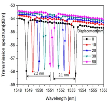
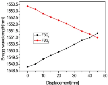
This paper proposes a new temperature-compensative displacement sensor with a pair of fiber Bragg gratings (FBG) attached to the inner and outer surfaces of an elastic metal band. The sensor can be also used as a temperature sensor with high sensitivity. The FBG pair shifted Bragg wavelengths in the same direction according to changes in the temperature. However, because the pressure of the metal band shifted a pair of Bragg wavelengths in the opposite direction, the displacement sensor could compensate for the effect of the temperature change in the proposed FBG pair. Results of the experiments showed that the two FBG displacement sensors responded linearly and symmetrically with respect to the displacement, and the displacement could be obtained using the difference between the two Bragg wavelengths.

Keywords: Displacement sensor, Fiber Bragg grating, Temperature compensation, elastic metal band

1. INTRODUCTION

A periodic change in the refractive index of the fiber core, and in turn produce the highest reflectivity at a certain wavelength.

The ambient temperature change and strain upon the optical fibers cause a change in the grating period and refractive index. Various sensors are used based on Bragg wavelength shift, which is caused by the changes in the grating period and refractive index due to the temperature change and strain on the fiber [1]. Of the various applications of fiber gratings, sensors using high-elastic cantilevers with the capability of temperature compensation have been largely reported [2-5]. The arc-shaped temperature- independent load sensor using a pair of FBGs has been also reported [6].

However, we experimentally demonstrated that an elastic circular band with grated fiber firmly attached can be used as a bending or displacement sensor instead of a cantilever. The proposed sensor and cantilever sensors are almost the same in terms of the principles of operation; however, the structural

variation of our system could provide other useful applications.

Because the structure of the cantilever and circular band are different, the investigation of the behavior of FBG sensors based on the circular band is essentially necessary for various sensor applications, including displacement sensors, weight gauge, accelerometers, and force sensors. For the evaluation of the sensor, the characteristics of our sensor, specifically, the linear relation between the response and displacement of the circular band and the sensitivity of the Bragg wavelength due to the position on the band at which the grated fiber is attached, should be determined. As fiber gratings are affected by both the temperature and strain experienced by the fiber, the displacement obtained should be compensated to reject the effects of temperature.

To remove the temperature effects, we proposed a method using two different fiber gratings as a pair, and demonstrated the feasibility of the method. The schematics and operational mechanism of our system are as follows: Two different grated fibers are firmly attached to the inner and outer surfaces of the elastic circular band. When the band is pressed, the grating periods of the gratings are changed and the Bragg wavelength shifts [7].

In this research, we are concerned with whether the Bragg wavelength shifts at the inner fiber gratings and whether the outer fiber gratings show symmetrical behaviors. Both Bragg wavelengths show the same temperature characteristics. If both the Bragg wavelengths shift at the same rate with respect to the Department of Electromic Engineering , Honam University 417, Eodeung-

daero, Gwangju 62399, Korea

+

Corresponding author: [email protected]

(Received: Jan. 30 2018, Revised: Mar. 20, 2018, Accepted: Mar. 20, 2018)

This is an Open Access article distributed under the terms of the Creative Commons Attribution Non-Commercial License(http://creativecommons.org/

licenses/bync/3.0) which permits unrestricted non-commercial use, distribution,

and reproduction in any medium, provided the original work is properly cited.

(2)

Kwang Taek Kim and Dong Geun Kim

J. Sensor Sci. & Tech. Vol. 27, No. 2, 2018 83 change in ambient temperature, the displacement of the band can be measured absolutely using only the two Bragg wavelength shifts without any further work.

2. Device Structure and Operational Principle

The Bragg wavelength shift due to bending of the fiber is known to be almost zero, but the grated fiber firmly attached to the elastic body can be used as various sensors. Fig. 1 shows the proposed sensor system. The sensor consists of grated fiber attached firmly on an elastic band made of a long, narrow, and thin elastic metal plate. The grating period of the fiber gratings attached to the band can decrease or increase according to the relation between the direction of displacement and position of the grated fiber on the band. As depicted in Fig. 1, the grating period of the fiber grating on the outer surface may increase, and the Bragg wavelength is expected to increase. The grating period on the inner surface may decrease, and the Bragg wavelength is expected to decrease in turn.

Generally, the grating period increases with increasing temperature and the Bragg wavelength, in turn, increases with increasing grating period. In the proposed sensor, because the grated fibers are firmly attached to the bent surfaces, the behaviors of these grated fibers can be different from the grated fiber without any constraint. To form a temperature-compensated sensor, both grated fibers on the inner and outer surfaces of the band should have the same temperature profiles.

Fig. 2 shows the fabricated sensor. The elastic band was made of a stainless-steel plate, which was 0.1 mm thick and 10.0 mm

wide. The stainless-steel plate is utilized as a spring. First, we fixed the fibers on either side of the plate using epoxy. We then connected both ends of the plate using epoxy. The radius of the elastic circular band was 52 mm.

3. RESULTS AND DISCUSSIONS

We fabricated the device and measured its transmission spectrum for various displacements using an optical spectrum analyzer. A pair of FBGs are designed such that the Bragg wavelength of the inner FBG is 4 nm longer than that of the outer one. The inscribed gratings span 10 mm along the fiber.

Fig. 3 shows the experimental results. FBG1 was attached to the

Fig. 1. Structure of displacement sensor using elastic metal band with a pair of FBGs attached.

Fig. 2. Image of fabricated displacement sensor using two FBGs attached on a metal band: (a) overall view: (b) view of a FBG attached on a metal band.

Fig. 3. Transmission spectrum of the two FBGs in accordance with

displacement.

(3)

Temperature-Compensative Displacement Sensor based on a Pair of Fiber Bragg Gratings Attached to a Metal Band

84 J. Sensor Sci. & Tech. Vol. 27, No. 2, 2018 outer surface and FBG2 was attached to the inner surface of the

band, as depicted in Fig. 1. The Bragg wavelengths of FBG1 and FBG2 shifted to the opposite directions at approximately the same rate with respect to the displacement. When the displacement was 40 mm, the Bragg wavelength of FBG1 shifted 2.2 nm to the longer wavelength and the Bragg wavelength of FBG2 shifts 2.1 nm to the shorter wavelength. Fig. 3 shows that the sharpness of the transmission spectrum remained constant during the bending of the metal band, unlike that in the cantilever-based FBG sensor [2-4]. This phenomenon results in uniform bending of the FBG.

Fig. 4 shows that both wavelength shifts are almost linearly proportional to the displacement. The displacement sensitivity of the Bragg wavelength was 0.055 nm/mm for FBG1 and 0.0525 nm/mm for FBG2. A thicker elastic metal meant greater sensitivity [8]. Because the proposed sensor uses the difference between the two Bragg wavelengths of the two FBGs, the sensitivity is actually 0.1075 nm/mm.

Research on sensitivity improvement was not performed in this study. The characteristics of the proposed sensor could depend on parameters such as thickness and properties of the metal plate and diameter of the band. The temperature change creates a change in the grating period, which results in a shift in the Bragg wavelength. Therefore, sensor applications of FBGs, aside from temperature sensing, require temperature compensation. We measured the response of the sensor for various temperatures under the same displacement. The ambient temperature rise may cause thermal expansion of the elastic band, and the expansion of the band, in turn, causes the expansion of the fiber gratings. The fiber expansion may cause Bragg wavelength shift.

Fig. 5 shows the transmission spectra from 40°C to 100°C with

the same displacement condition. A hotplate was used as the heater of the band. Fig. 5 shows the 1.18-nm and 1.12-nm shifts in both Bragg wavelengths between 40°C and 100°C. The temperature sensitivity of the Bragg wavelength shift was measured to 0.018 nm/°C. This is 1.67 times of the sensitivity of the conventional FBG of 0.011 nm/°C [9,10], which is a typical value for common fibers. This is because the expansion rate of the band metal is much greater than that of the fiber. When the fiber gratings are attached to metal with a high thermal expansion rate, the Bragg wavelength shift is more sensitive to temperature changes [1]. Because both the FBGs have the same temperature sensitivity, it is also possible to simply measure the temperature of one of the FBGs. Although the structure and operational principle of the sensor is simple and easily understood, it is worthwhile to illustrate the advantages of the sensor through experiment. The proposed sensor revealed distinguished features, including a wide range of displacement, high sensitivity, and a linear response. In addition, the sensor was able to simultaneously measure the displacement and temperature.

4. CONCLUSIONS

We implemented a displacement sensor that consists of elastic metal band and two fiber gratings, and demonstrated the measurement results for the sensor. In case of displacement, the measurement results show that both Bragg wavelengths shift in the opposite directions at almost the same rate. For a change in temperature, both wavelengths shift in the same directions at the same rate. We experimentally demonstrated that the displacement can be measured accurately at temperatures between 40°C and Fig. 4. Bragg wavelength shift of two FBGs with respect to dis-

placement.

Fig. 5. Transmission spectrum of two FBGs with change of envi-

ronmental temperature.

(4)

Kwang Taek Kim and Dong Geun Kim

J. Sensor Sci. & Tech. Vol. 27, No. 2, 2018 85 100°C. Several applications could be implemented by changing the structure, shape, and elasticity of the metal band.

ACKNOWLEDGMENT

This research was supported by The Leading Human Resource Training Program of Regional Neo industry through the National Research Foundation of Korea (NRF) funded by the Ministry of Science, ICT and Future Planning (NRF-2016H1D5A1910658)

REFERENCES

[1] C.-H. Lee, L. Lee, M.-K. Kim and K. T. Kim, “Charac- teristics of a fiber Bragg grating temperature sensor using the thermal strain of an external tube”, J. Korean Phys. Soc., Vol. 5, pp. 3188-3191, 2011.

[2] Z. Wenjun, D. Xinyong, J. Yongxing and Z. Chun-Liu,

“Cantilever-based FBG sensor for temperature-independent acceleration measurement”, IEEE Communications and Photonics Conference and Exhibition (ACP), Asia, pp. 1-6.

2009.

[3] C. Shen and C. Zhong, “Novel temperature-insensitive fiber Bragg grating sensor for displacement measurement”, Sens.

Actuators A Phys., Vol. 170, pp. 51-54, 2011.

[4] M. Mansoor Khana, N. Panwarb and R. Dhawanb, “Mod- ified cantilever beam shaped FBG based accelerometer with self temperature compensation”, Sens. Actuators A Phys., Vol. 205, pp. 79-85, 2014.

[5] L. Jin, W. Zhang, L. Jing, H. Zhang, B. Liu, Q. Tu, G. Kai and X. Dong, “Two-dimensional bend sensing with a can- tilever-mounted FBG”, Meas. Sci. Technol., Vol. 17, pp.

168-172, 2006.

[6] J. Hao, Z. Cai, Y. Gong, J. H. Ng, P. Varghese, and S. Taka- hashi, “A simple passive arc-shape temperature-indepen- dent load sensor using a pair of fiber Bragg Gratings”, Int.

J. Optomechatroni., Vol. 2, pp. 16-31, 2008.

[7] J.-M. Han, “Fabrication process of optical Bragg grating and its applications.” Doctoral Degree, Chonnam National University, Gwangju, Korea, 2006.

[8] D.-G. Kim, H. C. Kang, Y.-C Pan, J.?K.; Y.?C. Kim and M.

Song, “Sensitivity enhancement of a fiber grating tem- perature sensor combined with a bimetallic strip” Microw.

Opt. Technol. Lett., Vol. 56, pp. 1926-1929, 2014.

[9] A.D Kersey, M.A Davis, H. J. Petrick, M. LeBlanc, K.P.

Koo, C. G. Askins, M. A. Putnam and E. J. Friebele, “Grat- ing Sensors”, J. Lightwave Technol., Vol. 15, pp. 1442- 1463, 1997.

[10] K. T. Kim and I. S. Kim, “Measurement of thermo-optic

coefficient of a liquid using a cascade of two different fiber

Bragg gratings”, J. Sensor Sci. & Tech., Vol. 22, pp. 95-99,

2013.

수치

Fig. 3 shows the experimental results. FBG1 was attached to the
Fig. 5 shows the transmission spectra from 40°C to 100°C with

참조

관련 문서