Corrosion Fatigue of Austenitic Stainless Steel in Different Hot Chloride Solutions
A. Visser1,†, G. Mori1, M. Panzenböck2, and R. Pippan3
1CD Laboratory of Localized Corrosion, Montanuniversitaet Leoben, Franz Josef Strasse 18, 8700 Leoben, Austria
2Department of Physical Metallurgy and Materials Testing, Montanuniversitaet Leoben, Franz Josef Strasse 18, 8700 Leoben, Austria
3Erich Schmid Institute of Materials Science, Austrian Academy of Science, Jahnstraße 12, A-8700 Leoben, Austria (Received June 12, 2015; Revised June 12, 2015; Accepted July 09, 2015)
Austenitic stainless steel was investigated under cyclic loading in electrolytes with different chloride contents and pH and at different temperatures. The testing solutions were 13.2 % NaCl (80,000 ppm Cl-) at 80 °C and 43 % CaCl2 (275,000 ppm Cl-) at 120 °C. In addition to S−Ncurves in inert and corrosive media, the fracture surfaces were investigated with a scanning electron microscope (SEM) to analyse the type of attack. The experimental results showed that a sharp decrease in corrosion fatigue properties can be correlated with the occurrence of stress corrosion cracking. The correlation of occurring types of damage in different corrosion systems is described.
Keywords : corrosion fatigue cracking, stress corrosion cracking, austenitic stainless steel, pitting, chloride solutions
†Corresponding author: [email protected]
1. Introduction
In this work an austenitic stainless steel in a strain hardened condition is investigated under cyclic loading and corrosive conditions. The question is which type of damage differently aggressive media cause under cyclic loading and how those types of damage affect the fatigue limit.
In contrast to the investigated steel, the frequently used CrNi stainless steels are nowadays not only more expensive due to the high nickel content, but reach only moderate strength levels in the solution annealed as well as the strain hardened state. The concept of the investigated austenitic stainless steel however has the advantage of lowered costs by stabilizing the austenitic lattice with nitrogen and manganese instead of nickel.
Furthermore the high nitrogen content contributes to an enhanced strength level1,2), while maintaining toughness and improved pitting corrosion resistance. J. W. Parket al.3) showed that nitrogen accelerates also the repassivation process by promoting Cr enrichment on the surface.
It is well known that austenitic stainless steels are susceptible to transgranular stress corrosion cracking in chloride solutions, especially at high chloride concentrations
and low pH values4,5).Strain hardening increases the yield and tensile strength as well as it improves the fatigue properties. This treatment however also increases the sensitivity to stress corrosion cracking (SCC), compared to solution annealed material6,7). During fatigue testing SCC can interfere with corrosion fatigue (CF). Those two corrosion mechanisms are hard to distinguish from each other since both are originating from a slip-dissolution mechanism8). Molybdenum is known to detain SCC by retarding the initiation of localized corrosion in corrosive media under stress9,10).
A preferred initiation point for both, SCC and CF is pitting corrosion11). Pitting can shorten the crack initiation time considerably by providing a notch as a starting point for cracks and fracture12). Chromium, nitrogen and molybdenum raise the pitting resistance equivalent number (PREN) and thereby lower the susceptibility to this kind of attack13,14). In the present study the superposition of the aforementioned types of corrosive attack with pure corrosion fatigue is studied under mild and aggressive conditions.
2. MATERIAL AND SAMPLE PREPARATION
The investigated steel is purely austenitic without any δ-ferrite. The chemical composition is shown in Table 1, while Table 2 gives details regarding the mechanical
Table 1. Chemical composition of the investigated steel grade
Cr Mn Ni Mo N
PREN*
[%] [%] [%] [%] [%]
20 20 6 - 10 2 – 3 0.5 – 1 35 – 47
*PREN = %Cr + 3.3×%Mo + 16×%N15)
Table 2. Mechanical properties of the investigated steel grade at testing temperatures15,16)
Temperature Rp0.2 Rm At
[°C] [MPa] [MPa] [%]
25 1218 1282 20
80 1047 1124 18
120 970 1062 17
(a)
(b)
Fig. 1. S−N curves of the investigated steel tested (a) in 13.2 wt-% NaCl solution and glycerine at 80 °C with an R-ratio of 1 and (b) in 43 wt-% CaCl2 solution and glycerine at 120 °C with an R-ratio of 0.05, 20 Hz; (solid dots mark ruptures, open dots mark fatigue tests without rupture).
properties of the steel at room temperature and at the raised temperature (80 °C, 120 °C).
Corrosion fatigue (CF) was investigated using tensile specimens according to ASTM E46617). The preparation of the samples for CF tests included longitudinal turning to a diameter of 8 mm on a parallel length of 10 mm.
In order to guarantee defined and constant surface conditions, all specimens were electro-polished in H3PO4-H2SO4 electrolyte, removing about 100 µm of material from the surface. Thereby surface non-metallic inclusions and residual stresses caused by the machining process are eliminated. In the last step of preparation, the samples were cleaned with deionized water and ethanol.
3. EXPERIMENTAL
The load controlled CF tests were performed by using servo-hydraulic testing machines and double walled glass cells filled with one of the three testing solutions. The test solutions were inert glycerine, 13.2 wt-% NaCl and 43 wt-% CaCl2. Before the fatigue test started, the NaCl solution was set to a pH of 8, by adding NaOH, but without using a buffer solution. The temperature was controlled by a Pt-100 temperature sensor and held at a constant value of 120 °C by a thermostat. Due to the fact that there is no true fatigue endurance limit in an aggressive environment, the fatigue endurance limit (se) was therefore defined as the stress level, which three samples persevered for more than 1.2*107 load cycles. The load was applied uniaxially and in a sinusoidal waveform.
For the tests in the mild medium (13.2 wt-% NaCl, 80
°C) and glycerine at 80 °C, an R-ratio of 1 was set, so
that the specimens were tested under tension-compression conditions with zero mean stress. The tests in the highly aggressive medium (43 wt-% CaCl2, 120 °C) and glycerine at 120 °C were conducted at an R-ratio of 0.05, applying only tensile stresses.
4. RESULTS
Fig. 1(a) shows the investigated steel tested under cyclic load in the 13.2 wt-% NaCl solution and in glycerine at a temperature of 80 °C and an R-value of -1. The solid dots symbolize specimen rupture, the open dots no rupture. The solid curve describes the fatigue behaviour under inert conditions at 80 °C and can be compared to the dotted curve, which stands for the results in the mild chloride solution (13.2 wt-% NaCl, 80 °C).The curve
Initiation point of fracture(300x) 2 mm from crack start (3000x)
a b
Fig. 2. SEM-images of a fracture surface of the investigated steel tested under cyclic loading with 20 Hz and R=0.05 under inert conditions (glycerine, 120 °C) showing (a) the transgranular fatigue fracture and (b) fatigue striations.
Initiation point of fracture (300x) 2 mm from crack start (3000x)
a b
Fig. 3. SEM-images of a fracture surface of the investigated steel tested under cyclic loading with 20 Hz and R=−1 under mild conditions (13.2 wt-% NaCl, 80 °C)showing (a) the transgranular fatigue fracture with thin oxide corrosion products and (b) fatigue striations.
obtained in the chloride solution lies slightly under that in glycerine.
Fig. 1(b) presents the S/N-curves of the investigated steel tested in the 43 wt-% CaCl2 solution (solid line) and in glycerine at 120 °C (dotted line) and an R-value of 0.05. A medium loss of the endurance limit in the highly corrosive environment is observed.
To examine the type of damage, the fracture surfaces were investigated in the scanning electron microscope (SEM). Fig. 2, 3, and 4 illustrate the fracture surfaces after testing the steel in the different media. All the SEM images are taken with the crack growth starting from the specimen surface.
As shown in Fig. 2 the cracking under intert conditions is transgranular throughout the fracture surface and fine fatigue striations can be observed which run along metal grains. The tests under inert conditions result in typical pure fatigue fractures.
Fig. 3 shows images of the fracture surface of the investigated steel tested in the mild medium (13.2 wt-%
NaCl, 80 °C) at R=−1. Under these conditions it shows only a few corrosion-related signs of damage, such as thin oxide corrosion products (Fig. 3(a)) and in some cases also pitting. As in Fig. 3(b) the fractures are dominated by fatigue striations.
In Fig. 4 the fracture surface of a specimen tested in the aggressive medium (43 wt-% CaCl2, 120 °C) at R=0.05is depicted. The fracture surface shows a fan shaped structure near the initiation point of fracture (Fig.
4(a) and 4(b)). In 2 mm distance from the crack start the fracture surface shows a combination of facetted structures and normal fatigue crack growth (Fig. 4(c) and 4(d)).
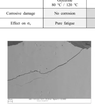
Fig. 5 presents the specimen surface, which is marked by secondary cracks. The branched cracks at the crack start are a sign for SCC.
5. DISCUSSION
The results of both the S/N-curves and the investigation of the fracture surfaces are summarized in Table 4. It
300x 3000x
Initiationpoint of fracture
a b
2mmfromcrackstart
c d
Fig. 4. SEM-images of a fracture surface of the investigated steel tested under cyclic loading with 20 Hz and R=0.05 under aggressive conditions (43 wt-% CaCl2 solution, 120 °C) showing (a, b) the fan shaped structure near the initiation point of fracture and (c, d) the facetted structure in a 2 mm distance from the crack start.
Table 3. Types of damage observed in CF-tests depending ontesting conditions Glycerine
80 °C / 120 °C
13.2 wt-% NaCl, pH 8, 80 °C, R=−1
43 wt-% CaCl2
120 °C, R=0.05
Corrosive damage No corrosion CF (+ Pitting) CF + SCC (+ Pitting)
Effect on se Pure fatigue Small reduction of se Medium reduction of se
Fig. 5. SEM-image of the specimen surface of the investigated steel tested under cyclic loading with 20 Hz and R=0.05 under aggressive conditions (43 wt-% CaCl2 solution, 120 °C) showing a secondary crack.
compares the tests under inert conditions in glycerine to those under mild and aggressive conditions.
In glycerine only pure fatigue without any corrosive damage appears. The tests in the mild medium (13.2 wt-%
NaCl, 80 °C) with an R-value of -1 show only a small reduction of the endurance limit (se), compared to the glycerine curve. The SEM-images show only little corrosive damage such as corrosion fatigue and pitting.
Only a few fractures were initiated at a pit with the effect of a notch and then continued by corrosion fatigue. This observed effect of pitting on the fatigue limit was described in detail by S. I. Rokhlin et al.12).
The tests under aggressive conditions (43 wt-% CaCl2, 120 °C) with an R-value of 0.05show, that the investigated steel is susceptible to transgranularstress corrosion cracking
under those given conditions.This result is accordant to the findings of V. S. Raja et al.5), who stated that austenitic stainless steels are sensitive to transgranular SCC in chloride solutions, especially at low pH values. The steel suffers a medium reduction of se due to moderate SCC and pitting.
6. CONCLUSIONS
● From corrosion fatigue tests and fracture surface observations, it could be concluded that the observed types of damage correlate with the reduction of fatigue limit.
● Compared to pure corrosion fatigue (dissolved slip- steps) pitting causes a small reduction of se, while the superimposed occurrence of SCC further reduces the fatigue limit and can result in a medium reduction of the fatigue limit.
● The aggressiveness of the medium determined the type of damage in the fatigue test. The mild medium (13.2 wt-% NaCl, 80 °C) caused pitting, while the aggressive medium (43 wt-% CaCl2, 120 °C) induced both pitting and SCC.
References
1. S. Ramya, T. Anita, H. Shaikh and R. K. Dayal, Corros.
Sci., 52, 2114 (2010).
2. F. M. Bayoumi and W. A. Ghanem, Mater. Lett., 59, 3311
(2005).
3. J. W. Park, Rao V. Shankar and H. S. Kwon, Corrosion, 60, 1103 (2004).
4. Mannesmannröhren-Werke, Lexikon der Korrosion, Band 1, Mannesmann-AG, Düsseldorf (1970).
5. V. S. Raja and T. Shoji, Stress Corrosion Cracking: Theory and Practice, Woodhead Publishing, India (2011).
6. K-H. Tostmann, Korrosion, Wiley-VCH Verlag GmbH &
Co. KGaA, Germany (2001).
7. J. M. Silcock, Corrosion, 38, 144 (1982).
8. T. Magnin, ISIJ Int., 35, 223 (1995).
9. V. G. Gavriljuk and H. Berns, High Nitrogen Steels, p.
195, Springer-Verlag, Berlin Heidelberg (1999).
10. M. O. Speidel, Metall. Trans. A, 12, 779 (1981).
11. P. P. Milella, Fatigue and Corrosion in Metals, Springer- Verlag, Rome (2013).
12. S. I. Rokhlin, J. Y. Kim, H. Nagy and B. Zoofan, Eng.
Fract. Mech., 62, 425 (1999).
13. F. C. Campbell, Metallurgy and Engineering Alloys, p.
330, ASM International (2008).
14. E. Bardal, Corrosion and Protection, Springer-Verlag, London (2004).
15. C. Vichytil, Beitrag zum Verständnis der Schwingun- gsrisskorrosion austenitischer Stähle, Dissertation, Leoben, Montanuniversität Leoben (2012).
16. R.Sonnleitner, Zur Schwingungsrisskorrosion hochfester austenitischer Stähle, Dissertation, Leoben, Montanuni- versität Leoben (2009).
17. ASTM E466-96, Conducting force controlled constant amplitude axial fatigue tests of metallic materials, ASTM International (2002).
![Table 1. Chemical composition of the investigated steel grade Cr Mn Ni Mo N PREN* [%] [%] [%] [%] [%] 20 20 6 - 10 2 – 3 0.5 – 1 35 – 47 *PREN = %Cr + 3.3×%Mo + 16×%N 15)](https://thumb-ap.123doks.com/thumbv2/123dokinfo/5403821.218212/2.892.84.433.146.237/table-chemical-composition-investigated-steel-grade-pren-pren.webp)