Vol. 21, No. 4, pp. 42-50, August 2017
Velocity Controller Design for Fish Sorting Belt Conveyor System using M-MRAC and Projection Operator
Huy Hung Nguyen*, Minh Thien Tran*, Dae Hwan Kim*, Hak Kyeong Kim* and Sang Bong Kim*†
(Received 26 May 2017, Revision received 02 August 2017, Accepted 03 August 2017)
Abstract: A velocity controller using a modified model reference adaptive controller (MMRAC) and a projection operator for a fish sorting belt conveyor system with uncertainty parameters, input saturation and bounded disturbances is proposed in this paper. To improve the tracking performance and robustness of the proposed controller in the presence of bounded disturbances, the followings are done. Firstly, the reference model for the conventional model reference adaptive controller (CMRAC) is replaced by a modified reference model for a MMRAC to reduce unexpected high frequency oscillation in control input signal when the adaptation rate is increased. Secondly, estimated parameters in an adaptive law are varied smoothly under bounded external disturbances and a projection operator is utilized in an adaptive law for the proposed M-MRAC controller to be robust. Thirdly, an auxiliary error vector is introduced for compensating the error dynamics of the system when the saturation input occurs. Finally, the experimental results are shown to verify the better effectiveness and performance of the proposed controller under the bounded disturbance and saturated input than that of a CMRAC.
Key Words:Bounded Disturbance, Adaptive Control, Projection Operator, Saturated Input, Velocity Controller.
*†Sang Bong Kim (corresponding author): Department of Mechanical Design Engineering, College of Engineering, Pukyong National University.
E-mail : [email protected], Tel : 051-629-6158
*Huy Hung Nguyen, Minh Thien Tran, Dae Hwan Kim, Hak Keyong Kim: Department of Mechanical Design Engineering, Pukyong National University.
1. Introduction
In a fish sorting system (FSS), captured fishes are transported from a fish pump that pumps the captured fishes in a ship into a fish sorting line through a conveyor system. The captured fishes are sorted by an injured rate which is estimated by
using an image processing system. Thus, a conveyor system speed plays a key role in estimating injured rate of fishes with high accuracy. Accordingly, the velocity of the conveyor system should be controlled with suitable speed sufficiently to obtain the reliable recognition of the image processing system. The conveyor system in the fish sorting system consists of three or more conveyors that the desired velocities are defined in trapezoidal velocity profiles. To control the closed-loop dynamics of the conveyor system closely to the desired velocities, a system modeling is obtained to develop a model-based controller. However, the conveyor system has some uncertain parameters such as a
friction factor, a belt elastic factor, pulling force, etc. to be unmeasured in the conveyor system.
An adaptive controller1) with its important ability to system uncertainties without requiring explicit unknown plant parameter identification2) was considered. A conventional model reference adaptive control (CMRAC) tuning directly control parameters is one of main schemes utilized in an adaptive control field.3,4) Although asymptotic tracking could be achieved in CMRAC systems, the tracking performance in transient state could be poor5) because it is impossible to achieve a small deviation of the tracking error in transient with an insufficient adaptation rate.
For engineering systems, it should be noted that the control input signal is frequently saturated and has proved to be a source of performance degradation. An input control signal saturation could lead to a poor control performance and even a closed-loop system instability6,7) if its effects were not considered in the design of the controller.
In addition, estimated parameters in update laws can be varied smoothly in the presence of bounded disturbances.
This paper proposes a model reference adaptive control approach, in which the reference model is modified by a feedback of a modeling error signal8) for velocity control of the conveyor system in a FSS with uncertain parameters, saturated input and bounded disturbances. In the presence of bounded disturbance, a projection operator9) is utilized in update laws of the proposed controller to eliminate the drift phenomenon of control parameters. As well, an auxiliary error vector11) to compensate for its error dynamics is employed when saturation input occurs. The contribution of this paper is to apply the projection operator to the update laws in the presence of the auxiliary error vector. The closed-loop dynamics of the auxiliary error vector are proved to be bounded in this paper whereas the
reference10) did not prove it. Additionally, the boundedness of all signals of the modified model reference adaptive controller encountered with saturated input are proved, and the constraint of norm of modeling error vector, the feedback gain, and the adaptation rate are demonstrated.
Experimental results are shown to verify the effectiveness and the performance of the proposed controller.
2. System modeling
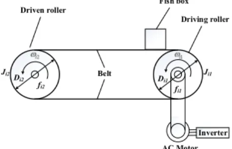
A typical conveyor system in the FSS shown in Fig. 1 consists of an on-loading conveyor (1st conveyor), a camera conveyor (2nd conveyor) for moving fishes pass the image processing system and a transition conveyor (3rd conveyor). Each conveyor consists of a mechanical subsystem and an electrical subsystem. The simplified model of the mechanical subsystem of the ith conveyor of the FSS is shown in Fig. 2 (i = 1,2,3).
On-loading conveyor
Camera conveyor Transition conveyor
Image processing system
Fig. 1 Typical conveyor system in the FSS
Inverter AC Motor Belt
Fish box Driven roller
fi2
Ji2 Ji1
fi1
Di2 Di1
Driving roller
Fig. 2 Simplified model of the ith conveyor of FSS
In Fig. 2, Ji1, Ji2 are moments of inertia of the driving roller and the driven roller, i1, i2 are the angular velocities of the driving roller and the driven roller, fi1, fi2 are friction coefficients of bearing inside the driving roller and the driven roller, and Di1, Di2 are diameters of the driving roller and the driven roller, respectively.
To simplify the mechanical subsystem modeling, the assumption 1 is proposed as follows:
● Assumption 1
Connection between motor shaft and driving roller is rigid and short.
Belt slippage on the rollers is negligible.
Fish box slippage on the belt is negligible.
To drive the mechanical subsystem, the electrical subsystem is used. The inverter with DC voltage input controls the induction motor to create sufficient torque to drive the mechanical subsystem as shown in Fig. 2.
Under the above assumptions, the ith mechanical driven system can be expressed by the following:
1 1
i Ji i fi i di t
(1)
where Ji = Ji1 + Ji2, fi = fi1 + fi2, di(t) is a bounded external disturbance torque and i is a sufficient torque to drive the mechanical subsystem of the ith conveyor given as follows:
* i k ui i
(2)
where ki is an amplifier gain, ui* is DC voltage input of the ith inverter to create the desired torque
i. ui* is defined as a saturated control input of the ith conveyor as follows:
min min
*
0 min max
max max
for for
for >
i i i
i i i
i i i
u u u
u u u u u
u u u
(3)
where ui* is a designed control input for the ith
conveyor by the proposed controller and uimin, uimax
are limited thresholds of the ith designed control inputs.
A dynamic FSS based on Eqs. (1)~(3) can be expressed in the state space as follows:
*
t
x Ax B u d (4)
where
11 21 31
T
x is an angular velocity
output vector of the FSS measured by encoders attached to the driving rollers, i1 is an angular velocity of the driving roller of the ith conveyor,
* * * *
1 2 3
sat u u u T
u u is a saturated control
input vector,
1 2 3
t d d d T
d is a bounded
external disturbance vector with didi
t ki andunknown constant matrices A B, 3 3 are given as follows:
11 11
22 22
33 33
0 0 0 0
0 0 , 0 0
0 0 0 0
a b
a b
a b
A B with
ii i i
a f J and biik Ji i.
3. Controller design
The control objective is to determine a designed control input vector
1 2 3
u u u T
u for a modified
model reference adaptive system with the saturated inputs and bounded disturbance such that the angular velocity output vector tracks an output vector of a reference model.
A modified reference model used for its output vector to track asymptotically a reference input vector r in trapezoidal type is chosen as follows:
m m m m
x A x B r r e (5)
m
e x x (6)
where >0 is an error feedback gain,
1 2 3
T
m m m m
x is an angular velocity output vector of the modified reference model, mi is the ith reference angular velocity, e is a modelling error vector,
1 2 3
r r r T
r is a reference angular
velocity input vector, and A Bm, m3 3 are given as follows:
1 1
2 2
3 3
0 0 0 0
0 0 , 0 0
0 0 0 0
m m
m m m m
m m
a b
a b
a b
A B
with ami, bmi are reference model parameters and chosen to satisfy the following assumptions 2 and 3 as follows.
Assumption 2: Given a known Hurwitz matrix
3 3 m
A and a known matrix Bm3 3 of full rank, there exits a unknown control gain matrix
3 3
K and an unknown positive definite diagonal constant matrix such that the following 3 3 equations are held:
and
m m
A A BK B B (7)
Assumption 3: A positive symmetric definite matrix P = PT > 0 is the solution of the following Lyapunov equation:
T
m m m
A P PA Q (8)
where Qm is a positive definite matrix.
Substituting Eq. (7) into Eq. (4), adding and subtracting Bmr, r yields:
*
m m m r
x A x B r r B u u (9)
where 1, B
m
1 and ur is a conventional control input vector as follows:
r t
u Kx r r d (10)
The first time derivative of e is given by:
m
m
* r
e A I e B u u
(11)
If u* = ur, e
AmI e
. Because the Am, and
AmI are Hurwitz matrices, it can be
concluded that e0 as t It implies that the . plant in Eq. (4) can track asymptotically the reference model in Eq. (5). However, the ideal control input vector cannot be implemented since the matrices K, , and the disturbance vector d(t) are unknown. Therefore, a designed control input vector u as estimation of ur is chosen in the following form:
ˆ ˆ ˆ ˆ t
u Kx r r d (12)
where ˆK, , are estimations of unknown control ˆ ˆ gain matrices , ,K and dˆ 3 is an estimated vector of an unknown constant vector d which is the average value vector of d(t) in Eq. (4).
A saturated input error vector is defined as:
u u u * (13)
From Eqs. (10)~(13), the first time derivative of e is given as:
+
m m
m
e A I e B Kx r r d
B d d u
(14)
where K K K ˆ , ˆ , ˆ and ˆ .
d d d
To remove the effect of the saturated input, an auxiliary error vector e is defined as:
m
ˆ
e A I e K u
(15)
where (Am I) is a stable Hurwitz matrix and ˆ 3 3
K is the adaptable parameter matrix.
Therefore, a new error vector is defined as follows:
u
e e e (16)
From Eqs. (14)~(16), the first time derivative of eu is given as:
+
u m u m
m
e A I e B Kx r r d
K u B d d
(17)
where ˆ
m
K K B
Control gains ˆK, , , ˆ ˆ ˆd in Eq. (12) are estimated by update laws based on projection operators will be designed in the following Theorem 1.
Theorem 1: A M-MRAC system of Eq. (4) is stable as long as a designed control input vector of Eq. (12) is given and update laws using a projection operator are given as:
ˆ 1Proj ˆ, ,Y f
(18)
ˆ 2Proj ˆ , ,
K K R g
(19)
ˆ3Proj , ,hˆ
d d S
(20)
where ˆ ˆ ˆ ˆ
T T T T
K
, ˆ ˆ ˆ ˆ
T T T T
K
1 2 3
T T T T
Y Y Y Y with Y1 B Pe xTm u T,
2
T T
m u
Y B Pe r and Y3 B Pe rTm u T, R Pe uu T,
T ,
m u
S B Pe f g, 3 are convex function vectors, h is a convex scalar function and 1, ,2 3 are 0 adaptation rates.
[Proof of Theorem 1] A candidate Lyapunov function is chosen to analyze the stability of the system as follows:
1
2 3
1
1 1
T T T
u u
T T T
V t trace
trace
e Pe K K
K K d d
(21)
The first time derivative of V(t) is given as:
1 1
2 2
3 3
2
2 ˆ ˆ
+
2 ˆ ˆ
+
2 ˆ ˆ
+ +2
T
u m u
T
T
T
T
u m
V t
trace
trace
e Q P e
Y
K K K R
d d d S
e PB d d
(22)
Using projection operator definition, its properties11) and update laws Eqs. (18)~(22), the following are satisfied:
1 1
2trace ˆ T Proj ˆ, , 0
Y f Y (23)
2 2
2trace ˆ T Proj ˆ , , 0
KK K R g R (24)
3 3
2trace ˆ T Proj , ,ˆ h 0
d d d S S (25) From Eqs. (23)~(25) and the Rayleigh principle, Eq. (22) can be rewritten as follows:
1 *
22 2
2 0
T T
u m u u m
u u u
V t
a d
e Q P e e PB d d
e e e
(26)
where a1min
Qm 2min
P 0, a1 0 and
*
d PBm d d l.
V t in Eq. (26) is negative semi-definite whenever
*
* 1
1
2 2
u u u
a d d
a
e e e (27)
This implies that e Ku, , , ,ˆ ˆ ˆ ˆK and ˆd are bounded from Eqs. (21), (26) and (27) and eu0 as t by Barbalat's lemma. Hence, ee and
e is bounded if and only if e is also bounded.
The boundedness of e is proven as follows:
A candidate Lyapunov is chosen as:
T 0
W e Pe (28)
Using Eqs. (15) and (20), the first time derivative of W is given as:
2
1 3 2 3
2 2 ˆ
T T
W m
a W
e Q P e e PK u
e
(29)
where 3 2 e PKT ˆT u 0 and 2 max1
a 0
P . By using the Gronwall Bellman Inequality, Eq.
(29) implies that
r r
+ +
u
u* u
x
eu
+ e
+
Controller Eq. (12)
Saturated Controller Eq. (3)
Conveyor Plant Eq. (4) Update laws
Eqs. (18), (19) (20) Auxiliary system Eqs. (15)
Modified Reference Model
Eq. (5)
x xm
e
d d/dt
d/dt
Fig. 3 Block diagram of the proposed controller
3
2
32 2
0 exp
W W t
e (30)
Using Eqs. (28) and (30), the followings are obtained:
Table 1 Comparison of M-MRAC with CMRAC
M-MRAC CMRAC
Ref.
model xmA xm mB r rm e xmA xm mB r rm
Update laws
ˆ1Proj ˆ, ,Y f
ˆ 2Proj ˆ , ,
K K R g
ˆ3Proj , , hˆ d d S
ˆ ,
ˆ ,
ˆ ,
ˆ .
T m T
m T
m T
m
K e PB x e PB r e PB r d e PB
3 2
lim T
t
e Pe (31)
23
min 2
lim T lim
t t
e Pe P e (32)
3
2 min
limt
e
P (33)
It can be proven that e is also bounded.
E.O.D The block diagram of the proposed controller is shown in Fig. 3 and comparison of M-MRAC with CMRAC is given in Table 1.
4. Experimental results
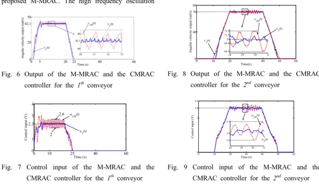
To evaluate the effectiveness of the proposed controller (M-MRAC) and compare it with the CMRAC, an experiment is carried out as shown in Fig. 4.
Fig. 4 Experimental conveyor plant
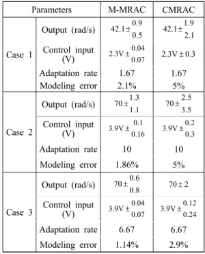
Fig. 5 Velocity profiles of all conveyors
The initial values of the state variables and the controller inputs are set to zero. Input voltages of the inverters considered as control inputs of the proposed controller can vary in range from u1min = u2min = u3min = 0 V to u1max = u2max = u3max = 5 V.
The parameters of the modified model reference system are given by am1 = am2 = am3 = -30, bm1 = bm2 = bm3 = 30. The error feedback gain is chosen as = 10, the fixed controller gains are chosen as 2 = 3.3, 3= 1.3 and the positive symmetric definite matrix
10 10 108 8 8
. diag
P The reference inputs
for the conveyor plant are angular velocity inputs and given in Fig. 5.
In order to demonstrate the effectiveness of the proposed controller, the following three case are considered.
Case 1: The adaptation rates of both CMRAC and M-MRAC are set to 1 = 1.67. It can be seen that both the output of the proposed M-MRAC x1(t) and the output of the CMRAC x1M(t) for the 1st conveyor track the reference input r1(t) as shown in Fig. 6. However, the output amplitude of the CMRAC varies more largely than that of the proposed M-MRAC. The high frequency oscillation
Fig. 6 Output of the M-MRAC and the CMRAC controller for the 1th conveyor
0 10 25 40 60
0 1 2.3 3 4
Time (s)
Control input (V)
2 2.6
u1(t) u1M(t)
Fig. 7 Control input of the M-MRAC and the CMRAC controller for the 1th conveyor
is generated in the control input signal u1M(t) of the CMRAC while the control input signal u1(t) of the proposed M-MRAC does not almost change as shown in Fig. 7 when the angular velocity output reaches 42.1 rad/s in Fig. 6.
Case 2: The adaptation rates of both CMRAC and M-MRAC are set to 1 = 10. The angular velocity output x2(t) of the proposed M-MRAC for the 2nd conveyor tracks the reference input r2(t) with tiny error (from -1.1 rad/s to +1.3 rad/s) while the angular velocity output x2M(t) of the CMRAC for the 2nd conveyor tracks the reference input r2(t) with error from -2.3 rad/s to +2.5 rad/s in Fig. 8. The control input u2M(t) of the CMRAC is also oscillated with higher frequency and amplitude than the control input u2(t) of the proposed M-MRAC as shown in Fig. 9. The maximum and minimum values of the control input of the CMRAC are 4.1 V and 3.72 V, respectively while the average value of the control input is 3.88 V. The control input for the proposed M-MRAC varies slower than that for the CMRAC. Therefore, the performance of the proposed M-MRAC is better than that of the CMRAC in this case
0 10 20 40 50 60
0 40 70 80
Time(s)
Angular velocity output (rad/s)
28 29 30 31
66.5 68.9 70 71.3 72.5 r2(t)
x2(t) x2M(t)
Fig. 8 Output of the M-MRAC and the CMRAC controller for the 2nd conveyor
0 10 20 30 40 50 60
0 3 3.9 4.5
Time (s)
Control input (V)
28 29 30 31
3.6 3.9 4.1
u2M(t)
u2(t)
Fig. 9 Control input of the M-MRAC and the CMRAC controller for the 2nd conveyor
Case 3: Similarly, the adaptation rates of both CMRAC and M-MRAC are set to 1 = 6.67. The angular velocity output x3(t) of the proposed M-MRAC for the 3rd conveyor also tracks the reference input r3(t) better than the angular velocity output x3M(t) of the CMRAC as shown in Fig. 10.
Because the reference input r3(t) is a step type, both the amplitudes of control input signals of the proposed M-MRAC and the CMRAC are large (15.5V and 12.5 V, respectively) in Fig. 11.
Therefore, the saturated control input u3*(t) is set to u3max= 5 V, and the angular velocity outputs of both the proposed M-MRAC and the CMRAC reach 90.3 rad/s in Fig. 10.
0 20 40 60
0 40 70 90.3
Time(s)
Angular velocity output (rad/s)
20 21 22 23 24
67.8 70 r3(t) 72.2
x3M(t)
x3(t)
Fig. 10 Output of the M-MRAC and the CMRAC controller for the 3rd conveyor
0 10 20 30 40 50 60
5 12.4 15.5
Time (s)
Control input (V)
9.1 9.6 12
2.8 3.66 3.9 4.1
u*3(t) u3(t) u3M(t)
u3M(t)
u3(t) and u*3(t)
Fig. 11 Control input of the M-MRAC and the CMRAC controller for the 3rd conveyor
The tracking performance of the proposed M-MRAC controller versus the CMRAC is given in Table 2.
Table 2 Modelling error of M-MRAC vs CMRAC
Parameters M-MRAC CMRAC
Case 1
Output (rad/s) 42.10.90.5 42.11.92.1 Control input
(V)
2.3V 0.04
0.07 2.3V 0.3 Adaptation rate 1.67 1.67
Modeling error 2.1% 5%
Case 2
Output (rad/s) 701.31.1 702.53.5 Control input
(V)
3.9V 0.1
0.16 0.2
3.9V0.3
Adaptation rate 10 10
Modeling error 1.86% 5%
Case 3
Output (rad/s) 700.60.8 70 2 Control input
(V)
3.9V 0.04
0.07 0.12
3.9V0.24 Adaptation rate 6.67 6.67 Modeling error 1.14% 2.9%
5. Conclusions
A ModifiedModel Reference Adaptive Controller for belt conveyors in a fish sorting system with uncertainty parameters, input saturation and bounded disturbances was proposed. The feedback of modelling error signal in the proposed M-MRAC controller obtained smaller modelling error than that in the CMRAC. The tracking performance of the proposed M-MRAC had better improvement in both transient state and asymptotic state than that of the CMRAC, and the high frequency elements in control input signals were reduced in the proposed M-MRAC when the adaptation rate was increased.
The error dynamics under the input saturation was compensated by the auxiliary output error. The experimental results showed that the proposed M-MRAC became more effective than the CMRAC when the adaptation rate was large and the error feedback gain was selected suitably.
Acknowledgement
This research was a part of the project titled
"Localization of unloading automation system related to Korean type of fish pump", founded by the Ministry of Oceans and Fisheries, Korea.
References
1. K. J. Astromn and B. Wittenmark, 2008,
"Adaptive Control", 2nd ed. Dover publication, INC.
2. A. M. D. Tran and Y. B. Kim, 2016,
"Dynamics Identification and Robust Control Performance Evaluation of Towing Rope under Rope Length Variation", Journal of the Korean Society for Power System Engineering, Vol. 20, No. 2, pp. 56-65.
3. T. T. Nestorovic, H. Koppe, and U. Gabbert, 2008, "Direct Model Reference Adaptive Control (MRAC) Design and Simulation for the Vibration Suppression of Piezoelectric Smart Structures", Communications in Nonlinear Science and Numerical Simulation, Vol. 13, No.
9, pp. 1896-1909.
4. S. Karason and A. Annaswamy, 1994, "Adaptive Control in the Presence of Input Constraints", IEEE Transactions on Automatic Control, Vol.
39, No. 11, pp. 2325-2330.
5. D. J. Wagg, 1994, "Transient Bounds for Adaptive Control Systems", IEEE Transactions on Automatic Control, Vol. 39, No. 1, pp. 171-175.
6. D. Y. Abramovitch, and G. F. Franklin, 1990,
"On the Stability of Adaptive Pole-Placement Controllers with a Saturating Actuator", IEEE Trans. on Automatic Control, Vol. 35, No. 3, pp. 303-306.
7. W. Sun, H. Gao and O. Kaynak, 2015,
"Vibration Isolation for Active Suspensions with Performance Constraints and Actuator Saturation", IEEE/ASME Transactions on Mechatronics, Vol. 20, No. 2, pp. 675-683.
8. V. Stepanyan and K. Kalmanje, 2010, "Input and Output Performance of M-MRAC in the Presence of Bounded Disturbances", In: AIAA Guidance, Navigation, and Control Conference, pp. 2-5.
9. T. Gibson, A. Annaswamy and E. Lavretsky, 2013, "Adaptive Systems with Closed–Loop Reference Models, Part I: Transient Performance", In: American Control Conf., pp. 3376-3383.
10. V. T. Duong et al., 2016, "Modified Model Reference Adaptive Controller for a Nonlinear SISO System with External Disturbance and Input Constraint", Lecture Notes in Electrical Engineering, Vol. 415, pp. 118-128.
11. E. Lavretsky, T. Gibson and A. Annaswamy, 2012, "Projection Operator in Adaptive Systems", arXiv e-Prints, arXiv:1112.4232v6.