Journal of the Korea Institute of Building Construction, Vol. 14, No. 1
http://dx.doi.org/10.5345/JKIBC.2014.14.1.001 www.jkibc.org
Investigation of Field Construction and Economic Efficiency for Steel Plate-Concrete Structures with Application of Parking Building
Han, Kwon-Gyu
1Park, Ho-Young
2Han, Kyung-Bo
2Choi, Byong-Jeong
2*1)Engineering & Construction Group, Samsung C& T, Seocho-Gu, Seoul, 137-857, Korea
1Department of Architectural Engineering, Kyonggi University, Yeongtong-Gu, Suwon, 443-760, Korea
2Abstract
The SC structure can have relatively liberal sectional surfaces, and allows modularization for pre-forming in factories and structural stability. It can be used for the shear walls in the core of general buildings or the structural members for parking buildings. In the future, it could be applied to moving large bus terminals, and widely used for general industrial structures as it can expedite the process compared to other methods. This study examined the applicability of SC structures to the retaining walls of a parking building and reviewed its economic value by comparing its construction term, quality control benefits, and cost compared to RC structures. It was found that SC structures are about 1.6-1.7 times more expensive than RC structures in terms of the cost of fabrication and installation. However, the construction term can be reduced by 27% to save indirect costs for constructors, as well as the cost of removing molds and material loss required when installing RC structures.
Keywords : steel plate-concrete structure, field construction, economical efficiency
1. Introduction
1.1 Research objective
With the improvement of quality of life and the advancement of architectural technology as well as diverse architectural demands in the rapidly changing and diversifying modern society, con- struction projects are becoming larger and high- er[1]. These changes demand members with struc- tural strength or convenience for safe composition in a small space. The structural members required for these conditions are high-strength concrete or high-strength steel materials. Studies have
Received : May 20, 2013
Revision received : November 14, 2013 Accepted : November 26, 2013
* Corresponding author : Choi, Byong-Jeong [Tel: 82-31-249-9702, E-mail: [email protected]]
ⓒ2014 The Korea Institute of Building Construction, All rights reserved.
been actively conducted on the development of high-performance concrete or high-strength steel materials and synthetic members through substantial construction industry-academic col- laboration[2,3].
In addition, to meet these requirements, struc-
tural advantages from members have been com-
bined to make a synthetic structure that can have
lighter weight and smaller section while having
higher rigidity and bearing more load compared
with the conventional members[4,5]. The steel
framed reinforced concrete(hereinafter SRC) col-
umn has been developed in a synthetic structure,
and is widely used, from which the steel
plate-concrete(SC) technology was developed that
is used for nuclear facility structures. As shown
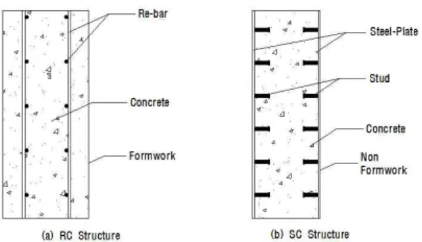
in Figure 1, the SC structure an integral synthetic
structure, is made by placing concrete between
sandwich steel sheets to complement the weak-
Investigation of Field Construction and Economic Efficiency for Steel Plate Concrete Structures with Application of Parking Building
nesses of materials, e.g. brittle failure of concrete and buckling of steel plate. The SC structure is a synthetic structure that can have a freer sectional shape in terms of constructability and space com- position compared with conventional CFT and SR structures. In addition, as with the SC structure it is possible to form a thinner long side structural wall compared with reinforced concrete(herein- after RC) structures, SC structures have been ac- tively studied in Japan and the United Kingdom, and the research findings are now being applied to actual building construction[6,7].
In addition, the SC structure allows easy quality control since it can be manufactured in a factory.
However, to apply the SC structure to a site, vari- ous elements are needed including transport and lifting plans, material carrying-in plan, and the assembly order to establish a thorough scheme of execution. This complex process is disadvanta- geous, and scant research has been done on the subject.
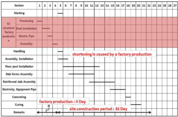
In addition, the SC structure has been limitedly employed for the structures of nuclear facilities (Shin-kori #3,4), but is expected to be widely ap- plied to structures with relatively fewer numbers of opening, to fit the diverse functions of modern structures, but thus far the constructability and economic feasibility of the SC structure needs to be studied. Therefore, this study aims to apply the SC structure to the walls of an RC-structured parking space, and to verify the applicability of the SC structure by performing a forecast and comparison of construction duration between RC and SC structures and by conducting a comparative analysis of economic feasibility between them to verify the applicability of the SC structure in the field.
Figure 1. RC structure and SC structure
1.2 Research method and scope
In this study, the SC structure was applied to the RC-structured parking building to examine the construction duration and the constructability of the SC structure. SC structure technique is ap- plied to the parking building because cracks on the RC structure and the moisture flowing in the cracks cause steel corrosion and ultimately have a great impact on the life span and safety of the building. When the SC structure is applied, these problems can be addressed, and the thickness of the retaining wall and the construction duration can be reduced compared with when using the RC structure. Therefore, the scope of this study is limited to the application of the SC to the walls of a RC-structured parking building.
1.3 Analysis of foreign cases of synthetic structural walls
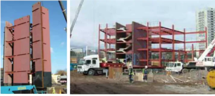
As shown in Figure 2, the overseas cases where
the composite structure of double-layered steel
plate, which is similar to an actual SC structure,
was adapted have been buildings built in England
in 2003, referred to as Bi-Steel corefast[6]. This
is the structural system that can greatly reduce
construction duration, and was applied to the
Birmingham 1 Tower, an 18-story OCN building
in England, which can include 640 people, and
it was usually employed in the core. As Table 1,
the core was installed for 4 stories at a time and
ties were finished in 5 days, and the entire con- struction duration was 120 days for an 18-story building when the conventional RC technique was employed, while it was 20 days for Bi-Steel[6,8].
Figure 2. Birmingham 1 tower (Bi-steel)
Table 1. Construction cases of Bi-steel Field Construction
case Bi-Steel
Construction RC Duration
Reducing Birmingham 1 Tower
(Core)
20days
(4 floor /5days) 120days 100days (84%) London Political
Science Building
(core) 14days 120days 106days
(88%)
2. Design of a parking building employing SC structure
2.1 Size of parking building
As indicated in Table 2, the building, analyzed by applying the RC structure in the underground part, is a composite hospital building located in Gangnam, Seoul. Its SC-structured lower part has operating rooms and medical equipment, and its ground part is steel-framed. The SC structure was applied to the structural part of the RC-structured underground parking induction ramp walls, and the economic feasibility and the construction du- ration and the lifting plan were compared and the applicability of the SC structure is scrutinized.
Contents
Site ○○ hospital, Gangnam-gu, Seoul Construction Time 2005. 7. ~ 2008. 10.
Total Floor Area 108,659㎡
Ramp Length of Parking
Garage 59.44m
Retaining wall Thickness of
Ramp 300~600mm
Width of Ramp Inside wall 8.5m, Outside wall 16m
Parking 570 Cars
The parking building studied in this research is RC-structured, which means that it has no col- umns and that slab and beams are directly con- nected with the retaining wall. Figure 3 shows the structure whose ramp length is 60m in the long side and 30m in the short side, and the height is 4.5m, and the retaining wall is 300-600mm.
Based on the dimensions, the reduction in con- struction duration and economic feasibility of the SC structure were compared.
Figure 3. Application area of SC structure at parking garage
2.2 Discussion of the structure to determine applicability of the SC structure and the design
To employ the SC structure in the conventional RC-structured parking ramp, the ratio of re- inforcement and structural requirements of the RC-structured parking ramp were determined. It was found that the SC structure should be made by estimating the critical stress and the nominal compressive strength in consideration of the in- terval between studs and the thickness of the steel plate when it is converted into the SC structure.
First of all, the maximum load of the RC structure
should be reviewed, and then the SC structure
Investigation of Field Construction and Economic Efficiency for Steel Plate Concrete Structures with Application of Parking Building
designed. The maximum load of the steel framed concrete retaining wall (
) on which the central axial load is placed was calculated using Eq.(1) in reference to the construction design cri- teria(KBC2009)[9]. Here, the sectional size of the structure was set at 1000x300mm, and the size of the main bar was set as D19.
′
--- (1)
Here
′ : nominal compressive strength of con- crete(MPa)
: yield strength of rebar(MPa)
: shear area of the retaining wall(㎟)
: sectional area of the main bar(㎟)
if calculated with these factors,
×
×
therefore, the maximum load(
) is,
× × ×
When the RC-structured parking ramp retaining wall is changed into the SC structure, the thickness of the SC structure that could bear the maximum load and have identical performance was calculated.
Here, the thickness of steel plate(SS400) for the SC structure is assumed as PL-6mm. The interval between studs was examined as 250mm for Plan(1) and as 200mm for Plan(2), to select an effective interval ratio to the price reducing factors that satisfy the structural requirements and to make an economical design.
In general, as the design method of the SC struc- ture, the design equation set out in Korea Electric Power Industry, KEPIC-SNG, confirmed in 2010, was utilized as shown in Eq.(2).
--- (2)
Here,
: nominal compressive strength of con- crete(MPa)
: buckling strength of steel plate(MPa)
: sectional area of steel plate(㎟)
: sectional area of concrete(㎟)
In addition, since the buckling of steel plate is an important factor to the SC structure, the buck- ling strength was set in accordance with the inter- val ratio of studs( )[11].
≤
--- (3) Here, when the yield strength of the steel plate(
) was set at 235MPa, Eq.(3) was calculated to be 39.13, the boundary between elastic and non-elastic buckling. Through this, the stud interval ratio was calculated to be 41.6( ) when using Eq.(1), and in this case the buckling of the steel plate is elastic. Therefore, the buckling strength(
) was calculated to be 198.2MPa when using Eq.(4).
--- (4)
Here : buckling length coefficient of the steel surface plate radially supported by studs(=0.7)
: vertical interval between studs(㎜) : thickness of steel plate(㎜)
: elastic coefficient of steel plate(MPa)
If the maximum load of the SC structure was calculated at 250×250㎜ of the stud interval for Plan(1),
× × × × × ×
Here, was the thickness of concrete, which could be calculated using a linear equation when
was hypothesized at
.
If × × × × × × was
calculated, the thickness of the SC wall was 282mm
Contract Cost
Contents Unit Price (won)
Cost of Construction Reducti cost on (won) Quant
ity Price
(won) Sum
(won) Concrete Material ㎥ 57,653 0.018
㎥ 1,037 1,181 ▼1,181
Construction 8,000 144
Stud Material EA 369 16
EA 5,904 29,904
Construction 1,500 24,000
Contract Cost
Contents Unit Price (won)
Cost of Construction Reducti cost on (won) Quant
ity Price
(won) Sum
(won) Concrete Material ㎥ 57,653 0.069
㎥ 3,978 4,530 ▼4,530
Construction 8,000 552
Stud Material EA 369 25
EA 9,225 46,725
Construction 1,500 37,500
sectional area of 1,000×282 in the SC structure, equivalent to the structural performance of the sectional area of 1,000×300 in the RC structure.
Similarly, Plan(2) was calculated using the equations above. However, the stud interval ratio was 33.13, which is included in the non-elastic buckling area, and the buckling strength of the steel plate (
) was calculated by applying 235MPa for yield strength(
), which is a difference. From the calculation, the thickness of concrete at the stud interval of 200 for Plan(2) was 219mm, and when 219mm was summed with 12mm thickness of steel plate, it resulted in 231mm, which appeared to have structural performance equivalent to that at 300mm thickness of concrete. Put simply, when the RC structure is changed with the SC structure to have the maximum load and the load stress equivalent to those of the RC structure, the thick- ness of the retaining wall decreases according to the stud interval ratio. There was an 18mm(6%) decrease at the stud interval of 250, and a 69mm(23%) decrease at the stud interval of 200.
3. Analysis of economic feasibility and con- structability
3.1 Discussion of economic feasibility according to the stud interval in the SC structure
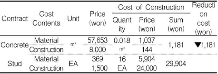
As described above, when the RC structure was replaced with the SC structure to have the max- imum load and the load stress equivalent to those of the RC structure, it was found to be effective in decreasing the thickness of the wall. Tables 3 and 4 provide the comparison of the construction cost, in terms of concrete material cost and reduc- tion in construction cost. Through the analysis, it was found that the reduction in cost resulting from stud interval ratio is greater than any other
cally, the SC structure with stud interval at 200 increased by approximately KRW16,000 per 1㎡
compared with the SC structure with stud interval at 250. In terms of the economic aspect, it is more economical to choose the stud interval at 250.
Table 3. The cost of construction(Stud @250)
Table 4. The cost of construction(Stud @200)
3.2 Discussion of manufacturability of the SC structure for the lifting plan
As mentioned previously, the economically ef- fective stud interval was 250, based on which the materials were prepared, and the shop drawings of the SC structure were made in Figure 4.
Figure 4. Unit module of SC structure
When the SC structure was applied, the thick-
Investigation of Field Construction and Economic Efficiency for Steel Plate Concrete Structures with Application of Parking Building
ness of the wall decreased by 18mm compared with a 300mm-retaining wall of the RC structure, but for convenience of manufacture the thickness of the wall was made to be 30mm. The retaining wall of the parking building, as shown in Figure 5, consisted of straight and curved sections, and the manufacturer of the SC structure and transport plan should be prepared individually. In addition, the size to be loaded on the cargo box of a truck is a minimum 2.3m and maximum 2.5m, and the product production by unit should not exceed a maximum of 2.5m.
Figure 5. Straight and curved section of SC structure
Table 5 indicates that the materials of construction were calculated in consideration of the transport of the sizes of members applicable to the straight section of the parking ramp. It is manufactured to 2,500mmx4,500mm(width x height) after deliberation with the manufacturer, and the transportable sizes in the table were determined based on the specification of the steel frame by reflecting the number of steel plates and the number of studs and the weight of reinforcement hardware. A total of 360 studs were needed when the stud interval was set at 250, a total of 45 tie-bars were used for fixation when the distance was set at 600. The weight appeared to be about 1.1 tons on the basis of the size of
a member of 2,500x4,500 for a 300mm-retaining wall.
Table 5. Material of construction (Straight section) Contract Element Standard Unit Quantity Unit
Weight (kg)
Weight (kg) note
W=2.5m H=4.5m
Steel plate
2.500×4,500 PL-6
(SS400) Sheets 2 530 1,060
Stud ST-16*100 EA 360 0.194 70 @250
Tie-Bar Φ 16*300 EA 45 @600
Total Weight(kg) 1,130
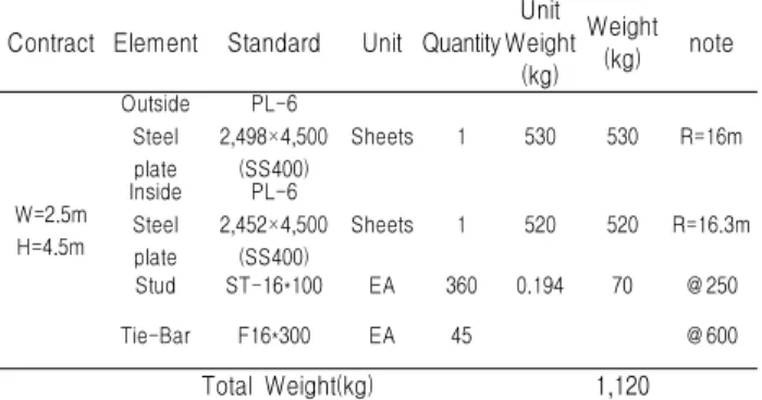
The curved section has a difference in the radius curvatures of the outer and inner section, and a different number or amount of materials is needed.
However, the production and transport plan can be prepared under the same condition as a straight section. As indicated in Table 6, the weight ap- peared to be 1.1 tons on the basis of a member size of 2,500 x 4,500 for a 300mm-retaining wall, similar to that of straight section.
Table 6. Material of construction(Curved section) Contract Element Standard Unit Quantity Unit
Weight (kg)
Weight (kg) note
W=2.5m H=4.5m
Outside Steel plate
PL-6 2,498×4,500
(SS400)
Sheets 1 530 530 R=16m
Inside Steel plate
PL-6 2,452×4,500
(SS400)
Sheets 1 520 520 R=16.3m
Stud ST-16*100 EA 360 0.194 70 @250
Tie-Bar F16*300 EA 45 @600