DOI : http://dx.doi.org/10.5394/KINPR.2011.35.7.569
A Study on Smart Heat Radiating Sheet for Protecting Electronic Equipments on the Ship
Dong Soo Choi*, Dong Il Kim†, Doh Yeol Kim**, Dong Han Choi***, Gyung Suk Kil**** and Jae Hwan Kim*****
†,*,**,*** Department of Radio Sciences & Engineering, Korea Maritime University, Busan, Korea
**** Division of Electrical and Electronics Engineering, Korea Maritime University, Busan, Korea
***** Department of Data Information, Korea Maritime University, Busan, Korea
Abstract : In this paper, we developed a Smart Heat Radiating Sheet(SHRS) having the absorption ability of more than 15 dB, and thermal conduction rate more than 20 W/mk for port logistics RFID(Radio Frequency IDentification) system by using AMP(Amorphous Metal Powder) and shielding sheet. Firstly, the EM(Electro_Magnetic) wave absorber samples were fabricated by using AMP and CPE (Chlorinated Polyethylene) with different composition ratios of 80 : 20 wt.% and 85 : 15 wt.%, respectively. Secondly, we fabricated the Smart Heat Radiating Sheet using the shielding sheet to attach EM Wave Absorber. As a result, the Smart Heat Radiating Sheet with absorption ability of 16 dB at 433 MHz and thermal conduction rate is 24 W/mk has been developed with the composition ratio of Amorphous Metal Powder : CPE = 85 : 15 wt.% and thickness of 5.5 mm.
Key words : RFID, EM wave absorber, SHRS (Smart Heat Radiating Sheet), AMP (Amorphous Metal Powder), absorption abilities, material constants
† Corresponding author, [email protected] 051)410-4314 * [email protected] 055)410-4932
** [email protected] 051)410-4932 *** [email protected] 051)410-4932 **** [email protected] 051)410-4414
***** [email protected] 051)410-4374
1. Introduction
Recently, according to the advancement of electronic and communication technology, the control of EM wave environments becomes an important issue. Thus, the countermeasures against the Electro-Magnetic Interference (EMI) and the Electro-Magnetic Susceptibility (EMS) are strongly recommended (D. I. Kim et al, 2004). Although the countermeasure techniques for EMC problem adopt the various methods such as filtering, cabling, grounding, isolating, and shielding, the EM wave absorber is lately attracting public attention because it can essentially eliminate unnecessary EM wave.
Especially, UHF band (433 MHz and 860 MHz ∼ 960 MHz) RFID system is widely accepted by industries such as port logistics, circulation, and mobile RFID field advantage of long communication range, and high speed transmission of data. However, RFID systems have several EMC problems such as dense mode, and decrease of communication range. Dense mode of RFID systems in a warehouse or harbour, where hundreds of antennas are
positioned in small area, cause the interferences between readers and tags. To avoid severe communication interruption between RFID systems, the EM wave absorber is applicable among readers. In addition, the communication range of RFID system is reduced when RFID Tag approached metal plate. In this case, the EM wave absorber can increase the communication range of RFID system by inserting an absorber between tag and metal plate.
2. Principle of the EM wave absorber
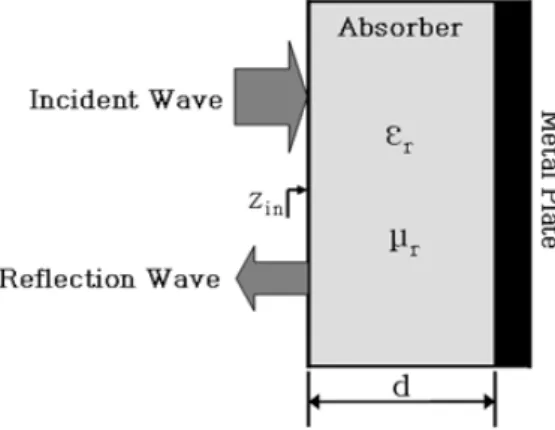
For an EM wave absorber made of a conductor-backed single layer as shown in Fig. 1, the Return Loss (RL) can be obtained from the equivalent circuit as follows (Smith F.
C.., 2002) and showed eq. (1).
log
(1)where, zin is the normalized input impedance from the surface of absorber. The normalized input impedance is expressed by eq. (2) (Smith F. C., 2002)(Snoek J. L, 1984).
(2)The normalized input impedance with no reflection condition is expressed as equation (3).
(3)Here,
is the wavelength, d is the thickness of the sample,
and
are the complex relative permittivity
and the complex relative permeability
, respectively.The ideal EM wave absorber can be designed using eq.
(3) and it is recognized that the important parameter is the complex relative permittivity, the complex relative permeability, and thickness of EM wave absorber(D. I. Kim, 2006).
Fig. 1 A single-layered EM wave absorber.
3. Fabrication of Em Wave Absorber
3.1 Sample preparation
We use amorphous metal powder and AMP as the EM wave absorbing material. AMP which is made of Fe-Cu-NB-Si-B is magnetic loss material(Hashimoto O. et al, 2004). Many amorphous metal powder compositions are studied to determine the effect of composition on magnetic properties, crystallization, ordering, stress relaxation, embrittlement, and formation. The chemical property of AMP is shown Table 1.
Table 1 Chemical Properties of AMP
Material Chemical composition
Amorphous metal
powder Fe73.5Cu1NB3Si13.5B9at.%
3.2 Measurement method
We used AMP as the initial material in order to make the sheet-type EM wave absorber samples. The magnetic loss materials is mixed with CPE as a binder, and a sheet type absorber samples are fabricated using an open roller. The open roller's surface temperature is controlled 70℃ during sample preparation because the surface temperature affects the EM wave properties of sheet-type absorbers(Dosoudil R., et al, 2010). In order to investigate the characteristics with different composition ratios of materials is 80 : 20 wt.%, 85 : 15 wt.%. The fabricating process of an EM wave absorber is shown in Fig. 2.
Fig. 2 Fabricating process of absorber.
4. Material Constants of EM Wave Absober
For investigating of the EM wave absorption abilities of the samples, the prepared sheet-type absorbers are punched into a toroidal shape with an inner diameter of 3.05 mm and an outer diameter of 6.95 mm (GPC7 type). The absorption abilities of the samples are investigated by using the HP 8753D network analyzer and gauged by measurement system as shown in Fig. 3. Fig. 3(a) is shown photo of the network analyzer HP 8753D and Fig. 3(b) presents a photo of the sample holder and sheet-type sample and toroidal shape sample.
We use the
method to calculate material properties from S-parameter and it is shown in Fig. 4.In Fig. 4, normalized input impedance and is shown in eqs.
(4) and (5).
tanh
(4)
tanh
tanh
tanh
(5)
and
is shown in equation (6) and (7).
(6)
(7)
and
is expressed by equations (4) and (5), which were shown in eqs. (8) and (9).
(8)
(9)
From equations (6), (7), (8), and (9) (Neo C. P. and Varaden V. K., 2004)(Naito Y., 1987), we can get
·
(10)
·
·
(11)(a) HP7853D
(b) Sample holders and samples.
Fig. 3 Measurement equipments.
Fig. 4
method.5. Simulated and Measured Results of the EM Wave Absober
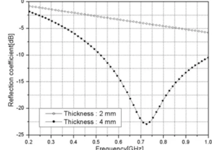
Figure 5 shows the reflection coefficients against the frequency of the EM wave absorber samples and the thickness of the samples shown is 1 mm and 2 mm. In Fig.
5, minimum reflection coefficients of EM wave absorber using AMP is 4.5 dB at 433 MHz when composition ratio is AMP : CPE = 80 : 20 wt.%. In Fig. 6, minimum reflection coefficient of EM wave absorber using amorphous metal powder reflection coefficient is 7 dB at 433 MHz when composition ratio is AMP : CPE = 85 : 15 wt.%. When composition ratio is 85 : 15 wt.%, the sample is suitable for EM wave absorber for RFID system at 433 MHz.
Fig. 5 Reflection coefficients of EM wave absorber when composition ratio is Amorphous Metal Powder : CPE
= 80 : 20 wt.%..
Fig. 6 Reflection coefficients of EM wave absorber when composition ratio is Amorphous Metal Powder : CPE
= 85 : 15 wt.%..
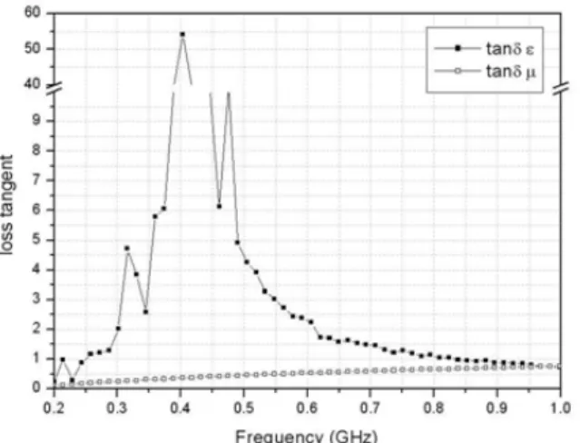
Fig. 7 Loss tangent of EM wave absorber when composition ratio of sample is Amorphous Metal Powder : CPE = 80 : 20 wt.%.
Fig. 8 Loss tangent of EM wave absorber when composition ratio of sample is Amorphous Metal Powder : CPE = 85 : 15 wt.%.
Fig. 9 Simulated results of absorption abilities.
Fig. 10 Comparison of simulated results and measured results.
Figures 7 and 8 show the loss tangents (dielectric loss tangent =
′′′
, magnetic loss tangent =′′′
) of each EM wave absorber sample and the thickness of the sample are 1 mm. Figure 7 is the loss tangent of AMP when composition ratio of AMP : CPE = 80 : 20 wt.% and Fig. 7 is the loss tangent of AMP when composition ratio of AMP : CPE = 85 : 15 wt.%. In this case, when composition ratio of AMP : CPE = 85 : 15 wt.% has higher values of magnetic loss tangent in frequency band of 200 MHz ∼ 1 GHz.The absorption ability of the EM wave absorber using the magnetic loss material is related to the magnetic loss tangent and has excellent characteristic by virture of the magnetic loss tangent. It is confirmed that AMP when composition ratio of AMP : CPE = 85 : 15 wt.% has higher magnetic loss tangent than AMP when composition ratio of AMP : CPE = 80 : 20 wt.% even though its magnetic loss tangent is lower than 1. Therefore, absorption ability of EM wave absorber with AMP when composition ratio of AMP : CPE = 85 : 15 wt.% shows better absorption ability at UHF band.
We controlled thickness and analyzed the characteristic.
In Fig.9 shows reflection coefficient of AMP when composition ratio is 85 : 15, and composition ratio is 80 : 20 wt.% with fixing frequency band of 433 MHz. Reflection coefficient of AMP when composition ratio is 85 : 15 wt.%
is 22.5 dB at 433 MHz with thickness of 5.5 mm, and Reflection coefficient of AMP when composition ratio is 80 : 20 is 36.5 dB at 433 MHz thickness of 10.2 mm. Even though AMP when composition ratio is 80 : 20 wt.% shows better absorption ability than AMP when composition ratio is 85 : 15, AMP when composition ratio is 80 : 20 wt.% is
too thick to apply the RFID system. Moreover, an absorption ability of AMP when composition ratio is 85 : 15 wt.% shows more than 20 dB. Thus, AMP when composition ratio is 85 : 15 wt.% is easy to apply RFID system.
Figure 10 shows comparison of simulated results and measured results. In this figure, measured results are slightly shifted to high and absorption abilities are lower than simulated results. Measured result at 433 MHz is 19 dB with thickness of 5.5 mm. The mearsured results agree with the theoretical ones in spite of the they include measuring errors slightly.
6. Conclusions
In this research, we investigated the EM wave absorbers using AMP which is magnetic loss material for the port logistics RFID system. These loss tangent values are calculated by material properties, and the absorption ability of the samples was measured by using network analyzer.
As a result, reflection coefficients of AMP when composition ratio is 85 : 15 wt.% superior to apply the RFID system with thickness of 5.5 mm. By analyzing magnetic loss tangent of the EM wave absorber, we confirmed that composition ratio of AMP : CPE = 85 : 15 wt%. has higher magnetic loss tangent than composition ratio of AMP : CPE = 80 : 20 wt%. Therefore, absorption ability of AMP composition ratio of AMP : CPE = 85 : 15 wt%. shows 19 dB at 433 MHz and it is more than 15 dB which is satisfying our goal for the port logistics RFID system.
Acknowledgment
This research work was supported by the Industry-University & Institute Partnership Division Center under the small and medium business administration and supported by the College of Engineering in Korea Maritime University.
References
[1] Dosoudil, R., Usakova, M., Franek, J., Slama, J., Gruskova, A.(2010), "Particle Size and Concentration Effect on Permeability and EM-Wave Absorption Properties of Hybrid Ferrite Polymer Composites," IEEE Transactions on Magnetics, Issue 2, vol. 46, pp. 436-439
[2] Kim, D. I. Son, J. Y. Park, W. K. and Choi, D. H.(2004),
"Broad-Band Design of Ferrite One-body EM Wave Absorbers for an Anechoic Chamber," Journal of the Korea Electromagnetic Engineering Society., Vol. 4, No.
2, pp. 51-55
[3] Kim, D. I.(2006), EM wave absorber Engineering, Seoul:
Daeyoungsa
[4] Neo, C.P., Varadan, V. K.(2004), "Optimization of carbon fiber composite for microwave absorber," IEEE Transactions on Electromagnetic Compatibility, vol. 46, Issue 1, pp. 102
[5] O. Hashimoto, et al.(2004), Technologies & Applications of Wave Absorber, CMC Publication co.
[6] Smith, F. C.(2002), "Thin wideband electromagnetic wave absorber for oblique incidence applications,"
Electronics Letters., Issue 8 , vol. 38, pp. 360-361 [7] Snoek, J. L.(1948), "Dispersion and Absorption in
Magnetic Ferrite at Frequency above one Mc/s,"
Physica, vol. 14, pp. 207-217
[8] Y. Naito(1987), Electromagnetic Wave Absorbers, Tokyo: New Ohm Publishing Co.
Received 12 July 2011 Revised 31 August 2011 Accepted 19 September 2011