• 검색 결과가 없습니다.

Reynolds Number Effects on Aerodynamic Characteristics of Compressor Cascades for High Altitude Long Endurance Aircraft

N/A
N/A
Protected

Academic year: 2021

Share "Reynolds Number Effects on Aerodynamic Characteristics of Compressor Cascades for High Altitude Long Endurance Aircraft"

Copied!
7
0
0

로드 중.... (전체 텍스트 보기)

전체 글

(1)

Reynolds Number Effects on Aerodynamic Characteristics of Compressor Cascades for High Altitude Long Endurance Aircraft

Taiki Kodama, Toshinori Watanabe, Takehiro Himeno, Seiji Uzawa

Department of Aeronautics and Astronautics, School of Engineering, University of Tokyo 7-3-1 Hongo, Bunkyo-ku, Tokyo 113-8656, JAPAN

[email protected]

Keywords: Aerodynamics, Cascade Flow, Reynolds Number, CFD, CIP-CUP

Abstract

In the jet engines on the aircrafts cruising at high altitude over 20 km and subsonic speed, the Reynolds number in terms of the compressor blades becomes very low. In such an operating condition with low Reynolds number, it is widely reported that total pressure loss of the air flow through the compressor cascades increases dramatically due to separation of the boundary layer and the secondary-flow. But the detail of flow mechanisms causes the total pressure loss has not been fully understood yet. In the present study, two series of numerical investigations were conducted to study the effects of Reynolds number on the aerodynamic characteristics of compressor cascades. At first, the incompressible flow fields in the two-dimensional compressor cascade composed of C4 airfoils were numerically simulated with various values of Reynolds number. Compared with the corresponding experimental data, the numerically estimated trend of total pressure loss as a function of Reynolds number showed good agreement with that of experiment. From the visualized numerical results, the thickness of boundary layer and wake were found to increase with the decrease of Reynolds number.

Especially at very low Reynolds number, the separation of boundary layer and vortex shedding were observed. The other series, as the preparatory investigation, the flow fields in the transonic compressor, NASA Rotor 37, were simulated under the several conditions, which corresponded to the operation at sea level static and at 10 km of altitude with low density and temperature. It was found that, in the case of operation at high altitude, the separation region on the blade surface became lager, and that the radial and reverse flow around the trailing edge become stronger than those under sea level static condition.

Introduction

In recent years, high altitude long endurance aircrafts come into cooperation for several objectives.

An example of their aircrafts is the Global Hawk, and some examples of their main missions are to investigate environment and to become platform for wireless communications 1) . The aircrafts that accomplish these missions are requested to fly at high altitude (about 20[km]) and at subsonic speed. The reason to fly at high altitude is not only to see further at wider angle, but also to fly above commercial

aircrafts. And flying at an altitude of around 20 km, the aircrafts experience relatively benign winds. The reasons to fly at subsonic speed are that the drag is kept down for long endurance, and the aerodynamic heating and shock associated with transonic or supersonic flight cause changes to the air sample.

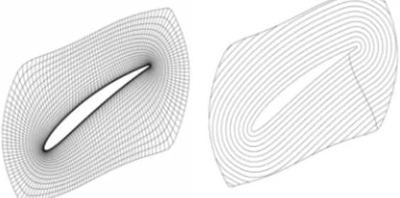
At high altitude and low speed, the Reynolds number in terms of the compressor blades becomes low as small as 10 5 . Figure 1 shows the total pressure loss of the flow through various compressor cascades as a function of the Reynolds number. It is widely known that total pressure loss increase dramatically with the decrease of Reynolds number.

Indeed, related to the aerodynamic characteristics of compressor cascade operating at low Reynolds number, a lot of experimental studies were conducted with low subsonic wind tunnels. For example, Rhoden et al. 3) conducted the experiment and investigated the performance changes in a series of C4 blade cascades.

Hobson et al. 4) investigated the flow over the suction surface of a second-generation controlled-diffusion compressor stator blades by laser-doppler anemometry measurements. But there were not so many investigations on the compressor cascade at the combination of low Reynolds number and high Mach number.

Fig.1 Reynolds number effects on loss of compressor cascade Reproduced

from Ref.(2)

(2)

In the present paper, the numerical simulation of low speed compressor was conducted to understand the mechanisms of loss generation due to the unsteady behavior of viscous flow. Then, as to high altitude long endurance aircraft, transonic flows in compressor cascade under high altitude condition were also numerically investigated.

Numerical Method

In the present study, two kinds of numerical codes were applied to conduct two different series of simulations to investigate changes of the flow field in compressor with decrease of with the decrease of Reynolds number. For the flows in transonic compressor cascade, the SHUS scheme with the third order MUSCL interpolations was employed, where the viscous fluxes were calculated in the central differential manner and time integration was implemented by the Euler implicit method with the LU-SGS scheme. On the other hand, for the unsteady flows at low Mach number in linear cascade, the Thermo CIP-CUP (TCUP) scheme 5) .

Thermo CIP-CUP

In the computation for low speed compressor cascade, the flow fields were described by Reynolds Averaged Navier-Stokes (RANS) equations as,

( ) u u

t + ⋅ ∇ = − ∇ ⋅

∂ ρ ρ ρ , (1)

( ) =

∂ +

u u :

t u ρ

ρ , (2)

( ) u e { } u q

t

e + ⋅ ∇ = ∏ ∇ ⋅ − ∇ ⋅

∂ ρ :

ρ . (3) Figure 2 shows the algorithm of TCUP schematically, which is the modification of the original CIP-CUP 6) . The combination of independent variables was selected as Q = ( ) u , T , p

T

. Based on the fractional-step method, the change of Q

T

in a time step

Δ t is divided into the change in advection phase, diffusion phase and acoustic phase.

In the advection phase, the convection equation of Eq.(4) are solved with CIP scheme.

0 ) ( r r r r

=

∂ +

u Q

t

Q (4) For instance, suppose that the convection equation

0 r r r r

∂ = + ∂

∂ + ∂

η ξ

V Q U Q t Q

c c

(5)

is solved with CIP scheme on a generalized coordinate system. The profile of the variable Q is interpolated with cubic polynomial. Then, according to the theoretical solution, the cubic-interpolated profile is shifted and the value at grid point ( ξ 0 , η 0 , ζ 0 ) is calculated by

) ,

( ) , ,

(

0 0 0 * 0 0

*

Q U t V t

Q r ξ η ζ = r

CIP

ξ −

c

Δ η −

c

Δ (6)

In the diffusion phase, the changes of variables Q

caused by the dispersion of momentum and heat were solved. Since the density remains unchanged in this phase, the variations in pressure and temperature are calculated by

( ) C

p

Q

DIF

t

T

T ~

*

*

*

*

*

ρ

= γ Δ

− , (7)

( C

p J

) Q

DIF

t p

p ~

1 1

*

*

*

*

*

μ ρ γ +

= − Δ

− , . (8) Heat input denoted by Q ~

DIF

is calculated as

[ T u q ] u t

Q

DIF

− ∂

=

* 2

*

: 2

~ ρ

ν

. (9) In the acoustic phase, on the assumption of isentropic change, the acoustic equation described as;

t u p C

S

= −∇ ⋅

2

1

ρ (10) is discretized in time-wise direction into

( ) C p t p u p t

n n

S

⎟⎟ Δ

⎜⎜ ⎞

∇ ⎛ ∇ +

−∇

Δ =

+

+

*

*

* 1

* *

* 1

* 2*

1 ρ ρ

, (11) where C

s

represents sound velocity, and solved implicity by BiCG-STAB method. The accompanying change of temperature is calculated by

( )

( )

** **

(

1 **

)

*

*

1

1

p p C T C

T

n

p J

n

+

p

=

+

+

ρ μ

ρ . (12)

Turbulence Model

As for turbulence model, the low Reynolds number

ω

k turbulence model (Wilcox, 1994) 7) was employed to estimate the eddy viscosity. This model has been proven to be superior in numerical stability to the k − ε model in the viscous sub layer near the wall. In the logarithmic region, the model gives good agreement with experimental results for adverse pressure gradient flows.

Distance Function

In general, to estimate the eddy viscosity based on turbulence model near the solid wall, the information of the distance from the wall is required. This is sometimes not a trivial task, especially in the CFD analysis of turbomachinery with body-fitted meshes.

In the present study, as a preprocessing, the distance function φ which indicates the normal distance from the surface of airfoil was generated by Level Set Method (LSM) 8) . In the LSM, the Hamilton-Jacobi type equation

) 1 )(

~ ( φ φ

φ = − ∇

sign t

(13) is solved iteratively with the boundary condition,

φ =0 on surface of airfoil. (14) If it converge, the property of distance function

= 1

∇ φ (15)

= 0 t D D ρ

= 0 t D Du

= 0 t D De

t u p C

S

∂ = −∇ ⋅

∂ ρ

2

1

= 0

t

∂ρ t

v

u = ∇ : T

∂ ρ ∂

{ } u q

t e

v

∇ ⋅ − ∇ ⋅

= T :

∂ ρ ∂ ADVECTION PHASE

DIFFUSION PHASE

ACOUSTIC PHASE

Convection equation solved with CIP scheme

Diffusion equation solved explicitly

Poisson equation solved iteratively

t+ Δt

Q

n

Q

*

Q

**

Q

n+1

Fig.2 Algorithm of TCUP

(3)

is obtained. In the present study, Eq.(13) was transformed into,

) ( )

~ ( φ φ

φ φ φ

φ sign sign

t ⋅ ∇ =

⎪⎭

⎪ ⎬

⎪⎩

⎪ ⎨

∇ + ∇

∂ , (16)

and solved by CIP scheme. For instance, distance function around generated around an airfoil 5) is shown in Fig.3.

Numerical Analysis

Low Speed Compressor

To understand the mechanisms of loss generation due to the unsteady behavior of viscous flow, the incompressible flow fields in the two-dimensional compressor cascade composed of C4 airfoils were numerically simulated with various values of Reynolds number and compared with the corresponding experimental data 3) .

The cascade parameters and inlet conditions are summarized in Table 2 and Table 3, respectively. The grid system for the computation, which is consisted of a structured H-O-H grid, is shown in Fig.6. On the exit boundary of computational domain, the static pressure was fixed as ambient pressure, 0.101325MPa.

On the inlet boundary, total pressure, total temperature and flow angle were determined and Riemann invariant was extrapolated from the adjacent inner cells, so that the mass flow rate should agree with that in the corresponding experiment. On the blade surface, no-slip and adiabatic conditions were imposed. The interface between two adjacent flow passages was treated as a periodic boundary.

Figure 7 shows instantaneous entropy contours of computational results. In the case at the highest Reynolds number, Fig.7(a), the entropy was found to be generated in the very thin region on the airfoil and in the wake. When the Reynolds number was decreased, shown in Fig.7(b), the thickness of boundary layer and wake was found to increase. Then at the lowest Reynolds number, Fig.7(c), there were observed the separation of the boundary layer on the suction surface and following vortex shedding.

Figure 8 shows calculated loss of total pressure through the cascade as a function of Reynolds number.

The value of the Reynolds number was changed widely from 3.18×10 4 to 4.70×10 5 . The experimental results are also plotted in this figure. The calculated trend of the loss shows good agreement with that of experiment qualitatively. The loss was found to increase with the decrease of the Reynolds number.

Particularly, the loss increased rapidly below 2.0x10 5 . From the corresponding flow field shown in Fig.7(c), the unsteady behavior of boundary layer was suggested to cause the loss generation.

Figure9 shows computational and experimental results of pressure distribution on the blade. In the cases with higher Reynolds number, as shown in Fig.9(a), good agreement was obtained. However, when the Reynolds number was decreased as small as below 10 5 , the separation point around the 70% chord shown in Fig.9(b), (c), and that around the 30% chord shown in Fig.9 (d) at the lowest Reynolds number, could not be captured in the computation. In the present computation, the turbulent transition was not considered. The transition model is expected for the quantitative prediction on the behavior of boundary layer at low Reynolds number.

Fig.6 Computational grid

Table2 Cascade parameter

Profile C4 Chord length 152.4[mm]

Camber angle 20[deg]

solidity 1.0 Stagger angle 34[deg]

Table3 Flow Conditions for Cascade Flow Simulation

Re Inlet Velocity Inlet Total Pressure 4.70×10 5 46.0[m/s] 1.02000×10 5 [Pa]

1.36×10 5 13.3[m/s] 1.01378×10 5 [Pa]

8.19×10 4 8.0[m/s] 1.01329×10 5 [Pa]

5.86×10 4 5.7[m/s] 1.01315×10 5 [Pa]

3.18×10 4 3.1[m/s] 1.01304×10 5 [Pa]

0 5 10 15 20

0.0E+00 1.0E+05 2.0E+05 3.0E+05 4.0E+05 5.0E+05 Re Number

Loss [ % Experiment

Calculation

Fig.8 Effects of Reynolds Number on Loss

Fig.3 Distance function around a blade

(4)

Transonic Compressor

Numerical simulations, as the preparatory investigation, the flow fields in the transonic compressor, NASA Rotor 37, were simulated under the several conditions, which corresponded to the operation at sea level static and at 10 km of altitude with low density and temperature. The developed numerical code was validated through comparison of computed comparison of computed total pressure and temperature distributions with the CFD simulations in a workshop by AGARD (Dunham 9) , 1998). 10) The simulation results are judged to show a satisfactory agreement with the experimental ones in comparison with CFD simulations. (See Dunham (1998) for details of the simulations in the workshop.)

The design parameters of the rotor are summarized in Table4. Table5 shows Reynolds number variation with altitude, where equivalent rotational speed and equivalent mass flow were fixed. Equivalent mass flow was 98% choke flow.

-1.5 -1 -0.5 0 0.5 1 1.5

0 0.2 0.4 0.6 0.8 1

x/ chord

Cp

(c) Re=5.86×10 4

-1.5 -1 -0.5 0 0.5 1 1.5

0.0 0.2 0.4 0.6 0.8 1.0

x/ chord

Cp

(d) Re=3.18×10 4

Fig.9 Pressure Distribution on the Blade

(c) Re=3.18×10 4

Fig.7 Instantaneous Entropy Contours

-1.5 -1 -0.5 0 0.5 1 1.5

0 0.2 0.4 0.6 0.8 1

x/ chord

Cp

Exp Calc

(a) Re=4.70×10 5

-1.5 -1 -0.5 0 0.5 1 1.5

0 0.2 0.4 0.6 0.8 1

x/ chord

Cp

(b) Re=8.19×10 4

(a) Re=4.70×10 5

(b) Re=8.19×10 4

(5)

The computational grid used in the present study is shown in Fig.10 and Fig.11. The grid system was consisted of a structured H-grid in the main flow region and O- and H- grids in the tip clearance region.

The main grid was composed of 124 cells in the streamwise direction (52 cells on the blade), 66 cells in the pitchwise direction, and 86 cells in the spanwise direction. The O- and H- grids embedded in the tip clearance region had 16 cells in the spanwise direction.

The total number of cells is 718,512. The minimum grid spacing on the solid walls was 5.0x10 -6 [m], which gave y + <1 on the walls.

Fig.12 shows entropy contours and streamlines near the tip of blade. Fig.12(a) shows entropy on the blade and near the casing regions become large. Fig.12(b) shows entropy on the blade become larger at 10 km of altitude than at sea level static condition.

Number of rotor blades 36

Tip solidity 1.288

Rotor inlet hub-to-tip diameter ratio 0.7 Rotor blade aspect ratio 1.19 Rotor tip relative inlet Mach number 1.48 Rotor hub relative inlet Mach number 1.13 Mass flow rate (kg/s) 20.93 Design wheel speed (rad/s) 1800

Tip speed (m/s) 454.136

Rotor total pressure ratio 2.106 Rotor adiabatic efficiency 0.877 Table4 Design overall parameter for NASA Rotor37

Altitude [km] 0 10 20

Inlet total pressure [Pa] 101325 26437 5475 Inlet total temperature [K] 288.15 223.15 216.65 Inlet velocity [m/s] 176 150 130 Rotational speed [rad/s] 1800 1584 1561

Tip speed [m/s] 462 407 401

Reynolds number 1.6E+06 4.8E+05 1.0E+05 Table5 Reynolds number variation with altitude

Fig.10 Computational grid for NASA Rotor37

Fig.11 Close-up of tip near leading edge

(a) Sea level static condition

Fig.12 Entropy contours and leakage flow streamlines

(b) 10 km of altitude condition

(6)

Fig.13 shows computational results of limiting streamlines and separation regions at sea level static condition and at 10 km of altitude conditions.

Separation regions were determined from the sign of the axial velocity component just off the blade surface.

On the pressure surface, separation regions are not found and flow is nearly axial at both conditions. On the other hand, on the suction surface, separation regions are found throughout the blade surface at both conditions. In the case of operation at 10 km of altitude, the separation region on the blade surface become lager, and the radial and reverse flow around the trailing edge become stronger than those under sea level static condition.

Conclusion

Two series of numerical investigations were conducted to study the effects of Reynolds number on the aerodynamic characteristics of compressor cascades. The conclusions were summarized as follows.

1. Calculated loss of total pressure through the cascade was shown as a function of Reynolds number and the calculated trend of the loss showed good agreement with that of experiment qualitatively. From the visualized flow field, the boundary layer and wake thickness increased with decreasing Reynolds number, and the boundary layer eventually separated and vortices were shed at very low Reynolds number. The unsteady behavior of boundary layer was suggested to cause the rapid increase of loss.

2. In the case of operation at 10 km of altitude, the separation region on the blade surface become lager, and the radial and reverse flow around the (a) Sea level static condition (Pressure surface)

(b) Sea level static condition (Suction surface)

(c) 10 km of altitude condition (Pressure surface)

Fig.13 Limiting streamlines and separation regions

(d) 10 km of altitude condition (Suction surface)

(7)

trailing edge become stronger than those under sea level static condition.

Acknowledgement

The present research was supported in part through the 21 st Century COE Program, “Mechanical Systems Innovation,” by the Ministry of Education, Culture, Sports, Science and Technology.

Nomenclature

t computational time [s]

u velocity vector [m/s]

ρ density [kg/m 3 ] e internal energy [J/kg]

T temperature [K]

p static pressure [Pa]

q heat flux [W/m 2 ] ∏ stress tensor [N/m 2 ] T ν viscous force [N/m 2 ] ∇ Nabra operator [1/m]

References

1) David J. Bents, Ted Mockler, and Jaime Maldonado, “Propulsion System for Very High Altitude Subsonic Unmanned Aircraft”, NASA/TM-1998-206636, April 1998

2) Bullock, R. O.; Johnsen, I. A. ,” Aerodynamic Design of Axial Flow Compressors”, NACA SP- 36, 1965

3) Rhoden, H. G., “Effects of Reynolds Number on the Flow of Air through a Cascade of Compressor Blades”, ARC R&M, No.2919, (1952).

4) Garth V. Hobson, “Effect of Reynolds Number on Separation Bubbles on Compressor Blades in Cascade” ,Journal of Propulsion and Power Vol.17, No.1, January 2001

5) Himeno, T., Watanabe, T., and Konno, A.,

“Numerical Analysis for Propellant Management in Rocket Tanks” , Journal of Propulsion and Power, AIAA, Vol.21, No.1(2005), pp.76-86.

6) Yabe, T. and Wang, P. Y., J. Phys. Soc. Japan, vol.60(1991), pp.2105-2108.

7) Wilcox, D. G., “Simulation of Transition with a Two-Equation Turbulence Model”, AIAA Journal, Vol. 32, pp.247-255

8) Sussman,M., Smereka, P., Osher, S., “A level Set Approach for Computing Solutions to

Incompressible Two-Phase Flow”, Journal of Computational Physics, vol.114(1994), pp.146 9) Dunham J., “CFD Validation for Propulsion

System Components”, AGARD-AR-355 (1998) 10) Ito, Y., Watanabe, T., Himeno, T., “Effect of

Endwall Contouring on Flow Instability of

Transonic Compressor”, IGTC 2007 Tokyo,

December 3-7, TS-042

수치

Figure 8 shows calculated loss of total pressure  through the cascade as a function of Reynolds number

참조

관련 문서