Development of Vibration Analysis Algorithm for Joined Conical- cylindrical Shell Structures using Transfer of Influence Coefficient
Dong-Jun Yeo*†and Myung-Soo Choi**
(Received 30 November 2012, Revised 4 January 2013, Accepted 18 January 2013)
Abstract:This describes the formulation for the free vibration of joined conical-cylindrical shells with uniform thickness using the transfer of influence coefficient. This method was developed based on successive transmission of dynamic influence coefficients, which were defined as the relationships between the displacement and the force vectors at arbitrary nodal circles of the system. The two edges of the shell having arbitrary boundary conditions are supported by several elastic springs with meridional/axial, circumferential, radial and rotational stiffness, respectively. The governing equations of vibration of a conical shell, including a cylindrical shell, are written as a coupled set of first order differential equations by using the transfer matrix of the shell. Once the transfer matrix of a single component has been determined, the entire structure matrix is obtained by the product of each component matrix and the joining matrix. The natural frequencies and the modes of vibration were calculated numerically for joined conical-cylindrical shells. The validity of the present method is demonstrated through simple numerical examples, and through comparison with the results of previous researchers.
Key Words:Vibration Analysis, Conical-cylindrical Shell, Natural Frequency, Numerical Analysis, Influence Coefficient
*†Dong-Jun Yeo(corresponding author) : Department of Power System Engineering, Chonnam National University.
E-mail : [email protected], Tel : 061-659-7133
**Myung-Soo Choi : Department of Maritime Police Science, Chonnam National University.
1. Introduction
Conical and cylindrical shells are commonly used as structural elements in many industrial fields such as the aerospace, submarine, chemical and civil industries and so on. Therefore, studies of their dynamic characteristics have been carried out by many researchers, and developed using various analytical methods. However, in contrast to the large number of studies on cylindrical and conical
shells considered separately, the analysis of free vibration in joined conical-cylindrical shells has not been widely reported in the literature.
To briefly review studies for combined shells, EI Damatty et al1) carried out experimental and analytical studies of the free vibration to assess the dynamic behaviors of combined conical-cylindrical shells. Patel et al2) studied the free vibration of laminated anisotropic conical-cylindrical and conical-cylindrical-conical shells using a finite element method. Irie et al3) applied a transfer matrix technique to calculate numerically the free vibration for joined conical-cylindrical shells.
Efraim and Eisenberger4) found the vibration frequencies of segmented axisymmetric shells using
a dynamic stiffness matrix. Caresta et al5) introduced a different approach to obtain the free vibrational characteristics of coupled conical- cylindrical shells. Two different methods corresponding to a wave solution and a power series method were used to obtain the shell displacements. Futhermore, expressions for the conical shell displacements were obtained for both the Donnel-Mushtari and Flügge theories. Lee et al6) investigated the free vibration characteristics of joined spherical-cylindrical shells with various boundary conditions using Flügge’s shell theory and Rayleigh’s energy method. Also, Soedel7) collected and reviewed the comprehensive literature dealing with the vibration of shells and plates.
In this report, the authors formulate an analysis algorithm for the free vibration of joined conical-cylindrical shell by applying the transfer influence coefficient method, which was developed on the basis of the concept of the successive transmission of the dynamic influence coefficients.
We apply the shell theory of matrix differential equations of first-order by applying the transfer matrix to the system and develop a new algorithm for the calculation of natural frequencies and modes by the transfer of influence coefficient8∼9).
From computation for the simple model, we compared the results of the present algorithm with those of others. We confirmed that the present algorithm could obtain solutions of high accuracy for joined shell structures and easily treat all boundary conditions by adequately varying the values of spring constants.
2. Theoretical Analysis
2.1 Formulation for conical shell
Fig. 1 shows the geometry and coordinates of a joined conical-cylindrical shell. The semi-vertex angle of the truncated conical shell is denoted by
, the radius of large edge by , the meridional length by , the thickness by , the cylindrical coordinates are taken as shown in the figures.
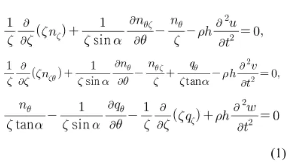
The equations of the shell based upon the Flügge theory are written by Flügge10) as:
sin
sin
tan
tan
sin
(1) where is the mass per unit volume and is the radian frequency. The components of the shearing force are given
sin
sin
(2) and the Kelvin-Kirchhoff shearing force and shear resultant are respectively,
sin
, sin
(3)
Fig. 1 Geometry and coordinate system of joined conical-cylindrical shell
The components of the membrane force are giv- en by,
sin
tan
sin
tan
sin
(4) And those of the moment are:
sin
sin
(5) sin
In the above equation and are displace- ments of the shell in the and directions, re- spectively, and the slope of the displacement ex- pressed as .
The flexural rigidities expressed as
, in terms of the Young’s modulus
and Poisson’s ratio .
For a steady state vibration of the shell, one may take
cos·
sin ·
(6) where denotes the circumferential wave number.
For simplicity of analysis, the following non-di- mensionalized quantities are also introduced
(7)
Substituting Eqs. (6)∼(7) into Eqs. (1)∼(5) and modifying the results, the matrix differential equa- tion on state vector can be written as follows
(8) where the state vector
is denoted by the dimensionless vari- ables, is the 8×8 square matrix and the co- efficients of the matrix are obtained as≡
sin
tan
sin
sintan
sintan
sin
sin
tan
sin
sin tan
sin
sintan
×
sin
sintan
sin tan
sin
sintan
tan
sin
sin
sin
sin
(9)
2.2 Formulation for circular cylindrical shell
For a circular cylindrical shell, the radius of the middle surface is denoted by , the axial lengthby , the cylindrical coordinates are taken as shown in Fig. 1. The governing equations of a circular cylindrical shell are derived as a special case of a conical shell by taking the limiting values → , and
sin→ tan→ The matrix equation has the same expression as Eq.
(8). In this case, the non-zero elements of the coefficients matrix become
(10)
2.3 Formulation of the transfer matrix
From Eq. (8), the state vector can be expressed as (11) Using the field transfer matrix of the shell, and substitution of the expression (11) into Eq.
(8) yields
(12)
The matrix is conveniently determined by integrating Eq. (12) numerically with the starting value (the unit matrix) which is obtained by taking in Eq. (12). In the numerical calculation, the elements of the transfer matrix are
conveniently determinate by using the Runge-Gutta-Gill method. The relationship between the state vectors and
of the arbitrary jth element is obtained as
(13) where is the field transfer matrix from nodal circle to and the superscript denotes the transposition. The physical quantities with tilde(symbol ‘∼’) and hat(symbol ‘∧’) represent the non-dimensional physical quantities on the left- and right-hand side of the nodal circle, respectively.
The relationship between the state vectors of the both-side ends of the arbitrary elements is expressed by the 4×4 sub-matrices and
of the field transfer matrix as
(14)From the equilibrium of the force at nodal circle where a conical and a cylindrical shell are joined together, we obtain
(15)
where is the point transfer matrix at nodal circle , and there are spring constants.
(16)
where and is the non-dimensional quantities of spring constants, and the coefficients become
(17)
2.4 Transfer of influence coefficient
The relationship between displacement vector , and force vectors and at arbitrary nodal circle is defined as (18)
where and are the 4×4 symmetric matrices of dynamic influence coefficients. The transmission rule of and at every nodal circle is obtained in the recurrent form.
From Eq. (14) and (18), the field transmission rule of the dynamic influence coefficients in the jth element is given by
… (19)
where
(20)
Substituting Eq. (15) into Eq. (18) the point transmission rule of dynamic influence coefficients at nodal circle is expressed as
(21) where
(22)
The dynamic influence coefficient matrix at the left-hand side of the system is expressed as
(23)
where is the point matrix at nodal circle 0.
When is singular, we cannot explicitly obtain the inverse matrix of . Hence, the modified measures to compute by using directly are introduced instead of Eq. (19) as
(24)
where
(25)
By adequately varying the value of spring constants and in of Eq. (25), we can deal with all the boundary conditions at the left-hand edge of the system.
2.5 Coordinate transformation
At nodal circle where a conical and a cylindrical shell are joined together, the following continuity and equilibrium relations must be satisfied:
cos sin
sin cos
cos sin
sin cos (26)
where the superscripts (c) and (o) express the conical and cylindrical shells, respectively. Eq. (26) is expressed by the displacement transformation
→ → (27) where
→
cos sin
sin cos
(28)
It is with the inverse matrix of → as
(29)
From Eq. (27) and (29), we obtain
→ → (30)
3. Numerical results and discussion
In this section, the free vibration of joined conical-cylindrical shells is investigated numerically using the foregoing theory. To confirm the validity
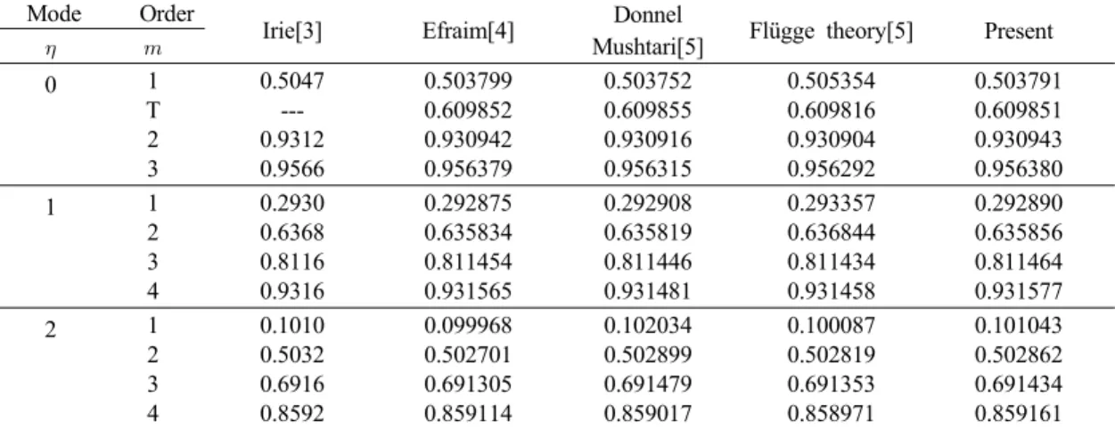
Table 1 Comparison of frequencies parameter for joined shell with free-clamped boundary conditions Mode Order
Irie[3] Efraim[4] Donnel
Mushtari[5] Flügge theory[5] Present
0
1 T 2 3
0.5047 --- 0.9312 0.9566
0.503799 0.609852 0.930942 0.956379
0.503752 0.609855 0.930916 0.956315
0.505354 0.609816 0.930904 0.956292
0.503791 0.609851 0.930943 0.956380
1 1
2 3 4
0.2930 0.6368 0.8116 0.9316
0.292875 0.635834 0.811454 0.931565
0.292908 0.635819 0.811446 0.931481
0.293357 0.636844 0.811434 0.931458
0.292890 0.635856 0.811464 0.931577
2 1
2 3 4
0.1010 0.5032 0.6916 0.8592
0.099968 0.502701 0.691305 0.859114
0.102034 0.502899 0.691479 0.859017
0.100087 0.502819 0.691353 0.858971
0.101043 0.502862 0.691434 0.859161
of the present analysis method, the computed natural frequency parameters are compared with those given by Irie at al3), Efraim et al4) and Caresta et al5) for joined conical-cylindrical shell of free-clamped boundary condition in Tables 1.
The numerical data is
and . From Table 1, it is observed that the present results are in fairly good agreement with those of previous researchers. The small discrepancies in results may be attributed to the different shell theories and analytic methods used in the papers. When , the frequency values of the mode with order corresponds to the first purely torsional mode. This torsional frequency parameter is omitted by Irie et al3), and reported by Efraim et al4) and Caresta et al5).
Fig. 2 and Fig. 3 show the frequency parameter
versus the circumferential wave number of joined conical-cylindrical shell for free-clamped and both simply supported boundary conditions.
From these figures, the general behavior of the frequency parameter curves is that the frequencies first decrease to a minimum value and then increase with the circumferential wave number.
However, the frequencies of 1st, 3rd and 6th orders
Fig. 2 Variation of frequency parameters with the circumferential wave number for clamped- clamped boundary conditions
Fig. 3 Variation of frequency parameters with the circumferential wave number for both simply supported boundary conditions
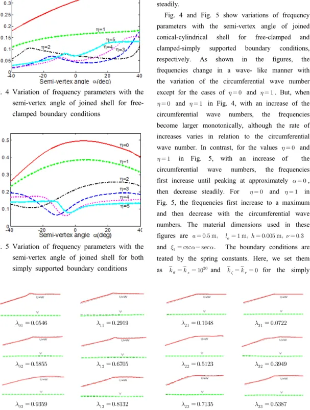
Fig. 6 Mode shapes of conical-cylindrical shell for free-clamped boundary conditions Fig. 4 Variation of frequency parameters with the
semi-vertex angle of joined shell for free- clamped boundary conditions
Fig. 5 Variation of frequency parameters with the semi-vertex angle of joined shell for both simply supported boundary conditions
in Fig. 3 initially increase to a peak, then decrease to a minimum value, after which they increase steadily.
Fig. 4 and Fig. 5 show variations of frequency parameters with the semi-vertex angle of joined conical-cylindrical shell for free-clamped and clamped-simply supported boundary conditions, respectively. As shown in the figures, the frequencies change in a wave- like manner with the variation of the circumferential wave number except for the cases of and . But, when
and in Fig. 4, with an increase of the circumferential wave numbers, the frequencies become larger monotonically, although the rate of increases varies in relation to the circumferential wave number. In contrast, for the values and
in Fig. 5, with an increase of the circumferential wave numbers, the frequencies first increase until peaking at approximately , then decrease steadily. For and in Fig. 5, the frequencies first increase to a maximum and then decrease with the circumferential wave numbers. The material dimensions used in these figures are m m m
and csc sec The boundary conditions are teated by the spring constants. Here, we set them as and for the simply
supported end and for the clamped end.
Fig. 6 shows the mode shapes of joined conical-cylindrical shell for the semi-vertex angle
presented in Fig. 2. Here, the first subscript 0 attached to represents the number of circumferential waves appearing on the mode shape and the second subscript 1 is the order of the vibration mode. The solid lines present the composition of the meridional/axial and radial displacements , and the broken lines projected along the center lines show the circumferential displacement .
4. Conclusions
The authors formulated an algorithm for the free vibration analysis of joined conical-cylindrical shells using the transfer of influence coefficient method, which was developed on the basis of the concept of the successive transmission of dynamic influence coefficients. We applied the shell theory of matrix differential equations of first-order by applying the transfer matrix to the system and developed a Matlab program for the calculation of natural frequencies and modes by the transfer of influence coefficient. Furthermore we carried out numerical computations in order to confirm its effectiveness.
The present method was found to obtain highly accurate results, and was able to adjust for varying boundary conditions by modifying the values of the spring constants.
Acknowledgement
This study was financially supported by Chonnam National University, 2009
References
1. A. A. El Damatty, M. S. Saafan and A. M. I.
Sweedan, 2005, "Dynamic Characteristics of Combined Conical-cylindrical Shells", Thin- Walled Structures, Vol. 43, No. 9, pp.
1380-1397.
2. B. P. Patel, M. Ganapathi and S. Kamat, 2000,
"Free Vibration Characteristics of Laminated Composite Joined Conical-cylindrical Shells", Journal of Sound and Vibration, Vol. 237, No.
5, pp. 920-930.
3. T. Irie, G. Yamada and Y. Muramoto, 1984,
"Free Vibration of Joined Conical-cylindrical Shells", Vol. 95, No. 1, pp. 31-39.
4. E. Efraim and M. Eisenberger, 2006, "Exact Vibration Frequencies of Segmented Axisymmetric Shells", Thin-Walled Structures, Vol. 44, No. 3, pp. 281-289.
5. M. Caresta and N. J. Kessissoglou, 2010, "Free Vibrational Characteristics of Isotropic Coupled Cylindrical-conical Shells", Journal of Sound and Vibration, Vol. 329, No. 6, pp. 733-751.
6. Y. S. Lee, M. S. Yang, H. S. Kim and J. H.
Kim, 2002, "A study on the Free Vibration of the Joined Cylindrical-spherical Shell Structures", Computer and Structures, Vol. 80, pp. 2405-2414.
7. W. Soedel, 1993, "Vibration of Shells and Plates", Marcel Dekker, Hongkong.
8. D. J. Yeo, 2005, "Development of Vibrational Analysis Algorithm for Truncated Conical Shells", Journal of the Korean Society for Power System Engineering, Vol. 9, No. 3, pp.
58-65.
9. D. J. Yeo and I. S. Cho, 2008, "Vibration Characteristics of Conical Shells with Linearly Varying Thickness", Journal of the Korean Society for Power System Engineering, Vol. 12, No. 2, pp. 35-40.
10. W. Flügge, 1973, "Stress in Shells, Springer- Verlag", Berlin.