1. Introduction
Nowadays, with the development of internet of things (IoT), the necessity of a display device showing various collected information is increasing day by day [1].
Among various display devices, liquid crystal displays (LCDs) is still the most used device, and many researches are being conducted to improve display performance [2-4]. In the LCD fabrication process, it is important to achieve uniform alignment of liquid crystal (LC) molecules on indium-tin-oxide (ITO) coated glass substrate surfaces [4]. Of the various LC alignment techniques, the rubbing treatment with respect to polyimide (PI) layers as LC alignment layer is widely used
in the LCD industry because of high productivity in mass production and its simplicity [6]. The PI layers are the most popular polymers in LCD manufacturing to align LC molecules parallel with some pretilt angle. In addition, the ease of use, stability, and reproducible results of the PI layer have made the use of the PI layer the industry standard. However, the application of new materials is being studied to lead the enhanced display performance [7-14].
Inorganic LC alignment materials with high dielectric constant (high-k) properties have been noted by several groups because of their optically transparent insulating characteristics, good adhesion to ITO surfaces, stability and chemical resistance, and high dielectric properties. Many
Liquid crystal alignment on rubbed self-assembled monolayers with fluorinated alkyl chain
Chan-Woo Oh*, Seok-Gon Hwang*, Sang-Geon Park**, Hong-Gyu Park***
Abstract In this paper, we investigated the vertical alignment characteristics of liquid crystals (LCs) on fluorinated self-assembled monolayers (FSAMs). For comparison, a commercialized homeotropic polyimide (PI) layer was used as an LC alignment layer. We confirmed the successful deposition of FSAMs and the change of FSAMs before and after rubbing treatment through contact angle measurement and atomic force microscopy. The optical transmittance spectrum of the FSAMs is similar to that of the homeotropic PI layer, which is a superior optical characteristic applicable to LC devices. When FSAMs were applied to the vertically aligned (VA) LC cell, uniform and vertical LC alignments were achieved. In addition, the voltage-transmittance characteristic of VA LC cell with FSAMs was superior to that of VA LC cell with the conventional homeotropic PI layers. These results indicate that the FSAMs are suitable as the homeotropic LC alignment layer for enhanced LC devices.
Key Words : fluorinated self-assembled monolayers, homeotropic alignment, liquid crystal alignment, rubbing treatment, voltage-transmittance characteristics.
This research was supported by Changwon National University in 2017~2018.
*School of Electrical, Electronic and Control Engineering, Changwon National University
**Division of Smart Electrical and Electronic Engineering, Silla University
***Corresponding Author: School of Electrical, Electronic and Control Engineering, Changwon National University (hgp [email protected])
Received November 05, 2018 Revised November 12, 2018 Accepted November 21, 2018
inorganic materials have been researched such as diamond-like carbon (DLC) [7,8], SiOx [9], Al2O3 [10,11], SiC [12], TiO2 [13], and In:ZnO [14]. In another approach, the application of the new polymer led to superior display performance. One of them is the use of self-assembled monolayer (FSAM) as a LC alignment layer. Clark group reported a SAM-based LC alignment as an alternative for conventional PI layer [15,16].
In addition, our group also reported that fluorinated SAM (FSAM) can be a good substitute for LC alignment [17,18]. In particular, FSAMs can be easily deposited at low temperatures by the gas-phase method.
In addition, the material of FSAM used in LC alignment process is significantly reduced compared to PI, resulting in a significant reduction in cost.
Here, we demonstrated the LC alignment characteristics through rubbing treatment on FSAM surfaces. A large amount of fluorine constituting the FSAM exhibited vertical orientation of LC molecules, and thus, the LC alignment characteristics of FSAMs were compared with those of the homeotropic PI layer. Physicochemical and optical analyses were conducted to confirm the FSAM deposition and the changes before and after rubbing treatment, and to observe the LC alignment state on the FSAM. In addition, we observed the voltage-transmittance characteristics that can evaluate low-power consumption by applying FSAM to vertically aligned (VA) LC cell as an LC alignment layer.
2. Experimental 2.1 Materials & preparation
We prepared FSAM via a gas-phase method. The ITO coated glass substrates were placed in a PTFE jars equipped with a PTFE sealed cap. Then, FSAM material, perfluorododecyl-1H,1H,2H,2H-triethoxy-sil ane-perfluorotetradecyl-1H,1H,2H,2H-trieth oxysilane (FDTS; Gelest SIP6720.5) (10 μl) was added to the bottle in a separate, smaller, open-topped vessel. The PTFE jars was held at 120 °C for 2 h in an oven during the reaction. For comparison, conventional homeotropic PI (JALS-696-R2, JSR Co. Ltd) layers were used. The homeotropic PI layers were uniformly prepared by a spin coating on ITO glass substrate and imidized at 180 °C for 1 h.
Both FSAM and homeotropic PI layer were rubbed for uniform LC alignment.
2.2 LC cell fabrication
The LC cells were fabricated based on the rubbed FSAM and homeotropic PI layer as an alignment layer in antiparallel configuration with a cell gap of 60 μm. The LC cells were filled with a negative LC (Δε = -3.2, Δn = 0.109; VA-J70, LIXON).
Additionally, VA LC cells were fabricated with a 4-μm cell gap on FSAM and homeotropic PI layer to measure the EO characteristics.
2.3 Contact angle & topological analysis
Contact angle analysis (Uni-Cam/A; GIT Software Technology) were used to confirm FSAM deposition. Atomic force microscopy (AFM; XE-100, Park Systems) was used todetermine surface roughness of FSAMs and homeotropic PI layers before and after rubbing treatment.
2.4 Application of LC devices
The LC alignment texture and pretilt angles of LC molecules were determined using a photomicroscope (BX53M; Olympus) and the crystal rotation method (TBA 107;
Autronic). The transmittance of FSAM and homeotropic PI layer were measured by an ultraviolet-visible-near infra-red (UV-Vis-NIR) spectrophotometer (V-670;
JASCO). FSAMs were applied to a VA cell for EO characterization.
3. Results and discussion
To investigate the homeotropic PI layers and the FSAMs coating on the ITO glass substrates, contact angle were measured.
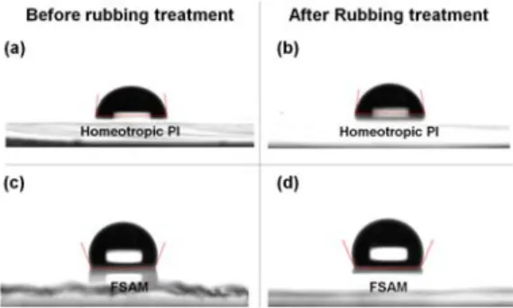
The contact angle of each surface was measured by the sessile drop method using a contact angle equipment. Figure 1 shows the photographs of the measured contact angles of the homeotropic PI layers and FSAMs before and after rubbing treatment.
Before rubbing treatments on the homeotropic PI layer and the FSAMs, the contact angles of the homeotropic PI layer and the FSAMs were 85.12° and 111.80°, respectively. The reason why the contact angle of FSAMs is higher than that of the homeotropic PI layer is because it contains more fluorine component. For comparison, the contact angle of ITO glass substrate was 60.19° [17]. The contact angles increased with the deposition of the homeotropic PI and FSAMs, indicating that these films were
successfully deposited. However, the contact angles of the homeotropic PI layer and the FSAMs were changed to 80.86° and 112.58° after rubbing treatments. The mechanical rubbing process causes physical deformation such as microgrooves through the stretching of the surface, thereby causing a change in the contact angle.
Therefore, the results of the contact angle before and after rubbing treatment indicate that the surface roughness change of FSAMs can be less than that of the homeotropic PI layer.
Fig. 1. Contact angles of the homeotropic PI layers and FSAMs before and after rubbing treatment:
(a-b) homeotropic PI and (c-d) FSAM.
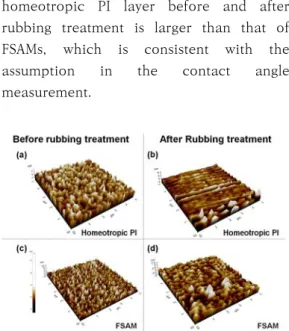
We observe the surfaces of the homeotropic PI layer and FSAMs through AFM to confirm these results. Figure 2 shows AFM images of the homeotropic PI layer and FSAMs before and after rubbing treatments. Before rubbing treatment, the surface roughness of the homeotropic PI layer and FSAMs were 0.373 nm and 1.680 nm, respectively. However, the surface roughness of these films after rubbing treatment were changed to 0.957 nm and 1.197 nm. These results show that the surface roughness change of the
homeotropic PI layer before and after rubbing treatment is larger than that of FSAMs, which is consistent with the assumption in the contact angle measurement.
Fig. 2. AFM images of the homeotropic PI layers and FSAMs before and after rubbing treatment:
(a-b) homeotropic PI and (c-d) FSAM.
We evaluated the feasibility of FSAMs as an alignment layer by fabricating LC cells using conventional homeotropic PI layer and FSAMs. Transparency of LC cell is important issue for high image quality in LCDs. Therefore, optical transmittance spectra of the LC cells with the homeotropic PI layer and FSAMs were measured as shown in Fig. 3. The average transparencies of the LC cells in the visible light spectrum range (380-780 nm) were 78.95% and 79.30%, respectively, which were very similar. This result indicates that the FSAM exhibits a transmittance spectrum similar to or better than that of a commercially available PI layer.
Fig. 3. Optical transmittance spectra of the LC cells with the homeotropic PI layers and FSAMs.
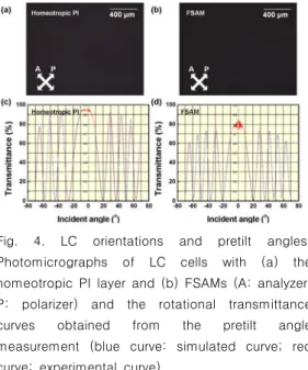
Figure 4 shows LC alignment characteristics including photomicrographs of LC cells and pretilt angles of LC molecules on the homeotropic PI layer and FSAMs. Fig. 4(a) and 4(b) shows photomicrographs of LC cells with the homeotropic PI layer and FSAMs. Both of the LC cells exhibited good alignment properties without any defects. In addition, all of these cells exhibited vertical alignment characteristics well. The rotational transmittance curves, as shown in Fig. 4(c) and 4(d), were obtained from which the pretilt angles of the LC molecules were computed via a comparison between simulated and measured data. Valid data were obtained when the LC molecules were well aligned along the preferred direction.
The measured data for rubbing treated homeotropic PI layer and FSAMs were in good agreement with the calculated data, indicating that good alignment was achieved. The pretilt angles by the crystal rotation method calculations of LC cells with the homeotropic PI layer and FSAMs were 87.99º and 89.27º, respectively. The
pretilt angle of LC molecules on FSAMs are applicable to VA-LCDs, which shows the possibility of FSAMs as homeotropic LC alignment layers.
Fig. 4. LC orientations and pretilt angles:
Photomicrographs of LC cells with (a) the homeotropic PI layer and (b) FSAMs (A: analyzer;
P: polarizer) and the rotational transmittance curves obtained from the pretilt angle measurement (blue curve: simulated curve; red curve: experimental curve).
The V-T characteristics of VA LC cells with the homeotropic PI layer and FSAMs was shown in Fig. 5. At 10% transmittance, the threshold voltages of VA LC cells with the homeotropic PI layer and FSAMs were 2.732V and 2.297V, respectively. The threshold voltage of VA LC cell with FSAMs was measured at 84% level compared with that of VA LC cell with the homeotropic PI layer. Since the thickness of FSAM is ultrathin, the capacitance of FSAM was increased. The increased capacitance of the FSAM induces higher polarization volume than that of the homeotropic PI layer [16].
This results in a higher potential difference between the top and bottom substrates.
Therefore, the FSAM allows LC molecules to
move at lower voltages. In addition, the reduction of the threshold voltage indicates less power consumption in LCD operation.
Fig. 5. Voltage-transmittance curve of VA LC cells with the homeotropic PI layers and FSAMs.
4. Conclusion
In conclusion, we demonstrated the possibility of the homeotropic LC alignment layer of rubbed FSAMs by comparison with the rubbed homeotropic PI layer. Contact angles and AFM measurement were used to confirm that the FSAM was well deposition on the ITO surface. The optical transmittance spectrum of FSAMs showed that FSAM (79.30%) was as transparent as the homeotropic PI layer (78.95%) and has no adverse effect on the transmittance. The LC cells with FSAMs showed uniform monodomain alignment comparable to a conventional LC cells with the homeotropic PI layers. Additionally, VA LC cells with FSAMs have a 16% lower threshold voltages than the conventional VA LC cell with the homeotropic PI layers. The results of this study indicate that devices can be made with high electro-optical performance by using FSAMs as LC alignment layers.
REFERENCES
[1] H.-Y. Cheong, T.-W. Kim, C.-H. Choi,
"Implementation of 3D virtual space documents using image information in real time", J. Korea Inst. Inf. Electron. Commun.
Technol. Vol. 11, pp. 40-44, 2018.
[1] M. Oh-e and K. Kondo, "Response mechanism of nematic liquid crystals using the in-plane switching mode", Appl. Phys.
Lett. Vol. 69, pp. 623-625, 1996.
[2] H.-G. Park, H.-J. Kim, M.-S. Kim, I.-H. Lee, and D.-S. Seo, "Electro-optical characteristics of ZrO2 nanoparticle doped liquid crystal on ion-beam irradiated polyimide layer", J. Nanosci. Nanotechnol.
Vol. 12, pp. 5587-5591, 2012.
[3] B. Liu, Y. Ma, D. Zhao, L. Xu, F. Liu, W.
Zhou, L. Guo, "Effects of morphology and concentration of CuS nanoparticles on alignment and electro-optic properties of nematic liquid crystal", Nano Res. Vol. 10, pp. 618-625, 2017.
[4] J. Cognard, "Alignment of nematic liquid crystals and their mixtures", Mol. Cryst. Liq.
Cryst. Suppl. Vol. 78, Chap. 1, pp. 6, 1982.
[5] H. Matsuda, D.-S. Seo, N. Yoshida, K.
Fujibayashi, S. Kobayashi, and Y. Yabe,
"Estimation of the static electricity and optical retardation produced by rubbing polyimide and polyamide films with different fabrics", Mol. Cryst. Liq. Cryst. Vol.
264, pp. 23-28, 1995.
[6] P. Chaudhari, J. Lacey, J. Doyle, E. Galligan, S. C. A. Lien, A. Callegari, G. Hougham, N.
D. Lang, P. S. Andry, R. John, K. H. Yang, M. Lu, C. Cai, J. Speidell, S.
Purushothaman, J. Ritsko, M. Samant, J.
Stӧhr, Y. Nakagawa, Y. Katoh, Y.
Saitoh, K. Sakai, H. Satoh, S. Odahara, H.
Nakano, J. Nakagaki, and Y. Shiota,
"Atomic-beam alignment of inorganic materials for liquid-crystal displays", Nature Vol. 411, pp. 56-59, 2001.
[7] J. Stӧhr, M. G. Samant, J. Luning, A.
C. Callegari, P. Chaudhari, J. P. Doyle, J. A.
Lacey, S. A. Lien, S. Purushothaman, and J.
L. Speidell, "Liquid crystal alignment on carbonaceous surfaces with orientational order", Science Vol. 292, pp. 2299-2302, 2001.
[8] P. J. Martin, A. Bendavid, C. Comte, H.
Miyata, Y. Asao, Y. Ishida, A. Sakai,
"Alignment and switching behaviors of liquid crystal on a-SiOx thin films deposited by a filtered cathodic arc process", Appl. Phys.
Lett. Vol. 91, 063516, 2007.
[9] H.-G. Park, Y.-H. Kim, B.-Y. Oh, W.-K.
Lee, B.-Y. Kim, and D.-S. Seo, "Vertically aligned liquid crystals on a γ-Al2O3 alignment film using ion-beam irradiation", Appl. Phys. Lett. Vol. 93, 233507, 2008.
[10] H.-G. Park, Y.-H. Kim, B.-Y. Kim, D.-H.
Kim, H. Yoon, and D.-S. Seo, "Van der Waals force contribution to the vertical alignment of liquid crystal on Al2O3 films using ion-beam method", Thin Solid Films Vol. 519, pp. 5654-5657, 2011.
[11] J. B. Kim, K. C. Kim, H. J. Ahn, B. H.
Hwang, D. C. Hyun, and H. K. Baik,
"Variable liquid crystal pretilt angles on various compositions of alignment layers", Appl. Phys. Lett.. Vol. 90, 043515, 2007.
[12] J.-W. Lee, B.-M. Moon, K.-M. Lee, Y.-H.
Kim, H.-G. Park, J.-H. Lim, B.-Y. Oh, B.-Y.
Kim, J.-Y. Hwang, C.-H. Ok, D.-S. Seo, and J.-M. Han, "Homogeneous liquid crystal orientation on ion beam exposure TiO2 surfaces depending on an anisotropic dipole field", Liq. Cryst. Vol. 37, pp. 279-284, 2010.
[13] J. H. Lee, E.-M. Kim, G.-S. Heo, H.-C.
Jeong, D. H. Kim, D. W. Lee, J.-M. Han, T.
W. Kim, D.-S. Seo, "Ion-beam-induced surface modification of solution-derived indium-doped zinc oxide film for a liquid crystal device with stable and fast switching properties", Opt. Mater. Vol. 84, pp.
209-214, 2018.
[14] D. M. Walba, C. A. Liberko, E. Korblova, M. Farrow, T. E. Furtak, B. C. Chow, D. K.
Schwartz, A. D. Freeman, K. Douglas, S. D.
Williams, A. F. kittnick, N. A. Clak,
"Self-assembled monolayers for liquid crystal
alignment: simple preparation on glass using alkyltrialkoxysilanes", Liq. Cryst. Vol. 31, pp.
481-489, 2004.
[15] G. Fang, Y. Shi, J. E. Maclennan, N. E.
Clark, M. J. Farrow, D. M. Walba,
"Photo-reversible liquid crystal alignment using azobenzene-based self-assembled monolayers: comparison of the bare monolayer and liquid crystal reorientation dynamics", Langmuir Vol. 26, pp.
17482-17488, 2010.
[16] S.-G. Hwang, H.-G. Park, M.-H. Park, and S.-G. Park, "Homeotropic alignment behavior of liquid crystal molecules on self-assembled monolayers with fluorinated alkyl chain", J. Vac. Sci. Technol. A Vol. 36, 041401, 2018.
[17] S.-G. Park, and H.-G. Park, "Alignment of liquid crystal molecules on self-assembled monolayer with fluorinated alkyl chain at different deposition time", Opt. Mater. Vol.
85, pp. 298-302, 2018.
[18] Gyoo-Seok Choi, ‘Development of Drive Method for Gray scale Representation by Liquid Powder Display Panel’, The Journal of The Institute of Internet, Broadcasting and Communication VOL. 9 No. 1, 2009
Chan-Woo Oh [Member]
• Feb. 2017: Changwon National University, School of Electrical, Electronic and Control Engneering, BA
• Mar. 2017 ~ Current: Changwon National University, Department.
Electronic Engneering, MS
<Research Interests> Liquid Crystal Application, Surface Coatings & Technology
Seok-Gon Hwang [Member]
• Feb. 2017: Changwon National University, School of Electrical, Electronic and Control Engneering, BA
• Mar. 2017 ~ Current: Changwon National University, Department.
Electronic Engneering, MS
<Research Interests> Liquid Crystal Application, Surface Coatings & Technology
Sang-Geon Park [Member]
• Jan. 2014: Nagoya University, Electrical Engneering, PhD
• Mar. 2016 ~ Current: Silla University, Division of Smart Electrical and Electronic Engneering, Assistant Professor
<Research Interests> Liquid Crystal Application, Surface Coatings & Technology, Medical Device
Hong-Gyu Park [Member]