INTRODUCTION
Over-actuated system is a system in which there may be more actuators than strictly needed to satisfy the control objectives. The over-actuated system usually appears in aerospace and maritime industries. For example, in order to improve the maneuverability and reliability, modern advanced aircraft, which has many and unconventional surfaces, generally configures with redundant actuators. And to perform a simple maneuver many actuators are required to work simultaneously. So
the traditional control method by using independently aileron, elevator and rudder to achieve a control requirement is not suitable anymore. Similarly, to achieve reliability with respect to sensor or actuator failure, most underwater vehicles are equipped more actuators than the necessary number required for nominal operation.
The over-actuated system is chosen due to several reasons (Fossen and Johansen, 2006) ·It improves the safety for controlled system in the
A control allocation sterategy based on multi-parametric quadratic programming algorithm
Tae-Yeong J
EONG, Sang-Won J
I1and Young-Bok K
IM1*
Training Ship Kaya, Pukyong National University, Daeyeon 3 dong, Namgu, Busan 608-737, Korea
1
Department of Mechanical System Engineering, College of Engineering, Pukyong National University, San 100, Yong Dang dong, Namgu, Busan 608-739, Korea
Control allocation is an important part of a system. It implements the function that map the desired command forces from the controller into the commands of the different actuators. In this paper, the authors present an approach for solving constrained control allocation problem in vessel system by using multi- parametric quadratic programming (mp-QP) algorithm. The goal of mp-QP algorithm applied in this study is to compute a solution to minimize a quadratic performance index subject to linear equality and inequality constraints. The solution can be pre-computed off-line in the explicit form of a piecewise linear (PWL) function of the generalized forces and constrains. The efficiency of mp-QP approach is evaluated through a dynamic positioning simulation for a vessel by using four tugboats with constraints about limited pushing forces and found to work well.
Keywords: Vessel, Control allocation, Dynamic positioning, Mp-QP algorithm, Robust control
*Corresponding author: [email protected], Tel: 051-629-6197, Fax: 051-629-6188 J Kor Soc Fish Tech 49 (2), 153-160, 2013
http://dx.doi.org/10.3796/KSFT.2013.49.2.153
case of actuator failure appears. It may be better than choosing a small set of actuators for reasons such as cost, mechanical design, maintenance, dynamic response, size and capability of actuators.
It can be divided into smaller sets and operated by difference control objectives.
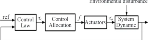
In over-actuated systems, the automatic distribution of control requirement among the actuators is called control allocation strategy as shown in Figure. 1. This unit exploits all of the maneuvering capabilities of the system subject to position, rate and power limit of actuators.
Commonly, control allocation problem is formulated as convex optimization. The objective is generally to minimize the error between total forces and moments t
agenerated by all actuators and command forces t
aproduced from the controller as well as to minimize the actuator thrusts.
The simplest control allocation methods for over- actuated system are formulated as unconstrained optimization algorithms such as cascaded generalized inverse method, daisy chaining method. And they can be modified to account for position and rate limits. Many practical solutions can be found and implemented efficiently in the safety-critical-real-time system by combining these methods with filtering and logic (Sordan, 1997;
Lindfors, 1993). However, they could not be implemented when the objective vector does not lie within the attainable moment set.
More complex methods consider control allocation as constrained optimization problems.
They are formulated as linear quadratic constrained (Bemporad et al., 2002; Tondel et al., 2003) or nonlinear quadratic constrained programming (Johansen, 2004; Johansen et al., 2004) and can be solved by using direct allocation, active set method
and so on. Until recently, it was believed that constrained optimization methods are too complex and too time consuming to realize in real-time system. However, with the dramatic developments in computing speed, as well as more efficient algorithms proposed, it has changed this thinking.
In this paper, we evaluate the efficiency of the linear quadratic constrained control method by using mp-QP algorithm through a ship-tugboats system simulation. In this study, the over-actuated system is considered with linear actuators produce the bounded forces in fixed directions. The advantage of this approach is that a feasible control allocation can be found if it exits. And the solution can be pre-computed off-line in the explicit form of a piecewise linear (PWL) function of the command forces and constraints. Furthermore, in this study, control law and control allocation algorithm are treated as separate disciplines. However, in some case where the control allocation can not guarantee the controlled objective, it should be observed and handled by the high-level motion control algorithm in order to avoid unacceptable degradation of performance.
This paper is organized as follows. In section II, the control allocation is formulated as mp-QP problem. Section III briefly presents the background and solution for mp-QP. The efficiency of this approach is evaluated in section IV through a dynamic positioning simulation of a vesselby using 4 tugboats. Some conclusions are given in section V.
Fig. 1. System architecture including control allocation.
ref Control
Law Actuators
Environmental disturbance
System Dynamic Control
Allocation
tc f ta
MATERIAL AND METHODS
Problem formulation for control allocationThe primary objective of control allocation is to compute a limited control force vector u ∈R
nwhich ensures that the command vector t
c〓h (x (t), u (t))
∈R
rcan be produced by actuators at all time.
Generally, the vector t
ccomprises the commanded forces (t
x, t
y, t
z) and commanded moments (t
f, t
q, t
j). Depend on the controlling purpose, not all 6 components of t
care specified. For example, in aerospace space application, we often concern about roll, pitch and yaw moment (t
f, t
q, t
j), while in the maneuvering of surface ship system, we consider about surge, sway force and yaw moment (t
x, t
y, t
j). If we assume that the system is equipped with n actuators and the actuator dynamics are neglected, the relationship between control vector u 〓(u
1, u
2, …, u
n)
Tand commanded vector t
ccan be expressed in the following form
t
c〓Bu, (1)
where B is often called the control effectiveness matrix. It presents the effect of actuator thrusts on desired dimensions. If the matrix B is square and non-singularity, the solution of Equation 1 is uniquely defined by u〓B
-1t
c. On the other hand, if
B is not square but full row rank (over-actuatedsystem), solving Equation 1 might seem like an easy problem where the unknown parameters are more than the number of equations. However, this may be difficult if we consider the constraints on the vectorsuch as position, rate and power limits.
The limits generally expressed in the form:
umin, i
≤u
i≤u
max, i(i 〓1, …, n) (2)
Given the limits, an exact solution might not exist, despite the redundancy. The solution of Equation 1 is transformed into optimization
problem, where the “best”vector u is respected to find down within the feasible region. In the optimization framework, constrained control allocation problem can be formulated as follows:
J
〓min ___ (u 1
TWu + sTQs),(3) 2
subject to
t
c-Bu + s〓0,
umin,i
≺u
i≺u
max,i(i〓1, …, n). (4)
where s is the slack variable that is introduced to minimize the difference between the total forces produced by all actuators and command vector t
c.
Wand Q are the weighting matrices. To achieveaccurate vector t
c, the slack variables should be close to zero. This is obtained by choosing Q≫W≻0.
If we define the new variables z〓(u
T, s
T)
T∈R
n+rand x 〓[t
cT, u
Tmin, u
Tmax]
T∈R
r+2n, the above optimization problem can be reformulated as mp- QP as follows:
J
〓min __ (z 1
TQz), (5)
2 subject to
A1z〓C1x, A2z〓C
2x.(6)
The matrices Q, A
1, A
2, C
2can be defined respectively as follows:
W 0nxr
Q〓 [ ] 0
rxn Q,
-I 0
nxrA1
〓[B -I
rxr], A
2〓 [ ]
Inxn0
nxr, (7)
0
nxr-I
nxn0
nxnC1
〓[I
rxr0
rx2n], C
2〓 [
Inxn0
nxr Inxn] .
Since W and Q are positive matrices, Equations
(5) and (6) define the convex quadratic program. It
means that the global solution can be verified. It has been found that the exact solution for this problem is a PWL function z
*(x) defined on the polyhedral partitions in the parameter domain and can be pre-calculated off-line using mp-QP algorithm (Kvasnica et al., 2004; Baotic, 2002;
Johansen et al., 2005).
Multi-parametric quadratic programming
Background
The mp-QP problem can be formulated as the original form:
Vz
(x) 〓min __ z 1
THz,2 (8) subject to Az ≤Cx + C
0.
where u ∈R
nzare the optimal variables, x ∈R
nxis the vector of parameters, and A ∈R
ncxnz, C ∈R
ncxnx, and C
0∈R
ncare the matrices of polyhedral constraints in (z, x) space.
To solve the mp-QP problem in (8), some important definitions are introduced to calculate the polyhedral partition of the parameter space (Kvasnica et al., 2004).
Definition 1: A convex set Q⊆R
ndescribing the intersection of a finite number of closed half-spaces
Qr〓{x∈R
nr| Q
xx≤Qc}, (9) for Q
x∈R
nRxrand Q
c∈R
nRis called polyhedron.
Definition 2: A bounded polyhedron P⊆R
nris called n
t-polytope.
It is clear to see from these two definitions that every polytope represents a convex compact set.
Definition 3: The linear inequality a′
x≤b iscalled valid for a polyhedron P if a′
x≤b holds forall x∈P. A subset of a polyhedron is called a face of P if it is represented as
F〓P{x∈Rnr
| a′
x〓b}.(10)
The faces of the polyhedron P of dimension 0,1,
nr-2, and n
r-1 are called vertices, edges, ridges and facets, respectively.
A solution for mp-QP problem
The problem present in (8) can be solved by applying the Karush-Kuhn-Tucker (KKT) conditions
Hz + AT
l〓0, l∈R
nc. (11) l
i(A
iz-Cix-C0i)〓0, (i〓1,…,n
c). (12)
l≥0. (13)
Az-Cx-C0
≤0. (14)
If H has a full rank, the solution for (11) is
z〓-H-1AT
l. (15)
Assume for a moment that, we can define the active set constraints for a given value x. So the Lagrange multiplier l
*can be calculated based on (12) and (15)
l
*〓-(A
*H-1A*T)
-1(C
0+ C
*x),(16) where A
*, C
*, C
0*contains the rows A
i, C
i, C
0i, z
*which corresponding to the active constraints. The optimal solution can be defined by substituting (16) into (15)
z*
〓H
-1A*T(A
*H-1A*T)
-1(C
0+ C
*x).(17) Substituting the expression (16) and (17) into (13) and (14) we can characterize the set of parameters where those expressions are valid, i.e., we obtain the closure of a critical region CR
0as follows
-(A
*H-1A*T)
-1(C
0*+ C
*x)≥0. (18)
AH-1A*T(A
*H-1A*T)
-1(C
0*+ C
*x)≤Cx*+C
0. (19)
This region is a convex polyhedral set and
represents the largest set of parameterssuch that the
combination of active constraints at the minimizer remains optimal (Johansen et al., 2005).
The constructing polyhedral partitions of the parameter space that explicitly defines the PWL function z* (x) has been presented in the reference (Baotic, 2002). The algorithm briefly describes as follows
Algorithm (for offline mp-QP solver) 1. Let (z
0, x
0) be the initial solution of (8).
2. For x 〓x
0, compute the Lagrange multiplier and the optimal solution (l
*, z
*).
3. Determine the active set constraintand build corresponding matrices A
*, C
*, C
0*.
4. Determine (l
*A0, z
*A0).
5. Characterize the critical region CR
0. 6. Partition the rest of the parameter space.
7. For each new sub-region, execute the same Algorithm 3.1.
Example about mp-QP
To evaluate the efficiency of the mp-QP method, a system using 3 actuators to produce 2 individual motions is studied. The effectiveness matrix is assumed to define as follows
1 2 1
B〓
[ ] 2 3 2 (20)
The problem is formulated in the optimal form (5)〜(7) with the following parameters
W〓I3x3
,
Q〓1000×I2x2
, (21)
umin i
〓-1, u
maxi〓1 (i〓1, …, 3).
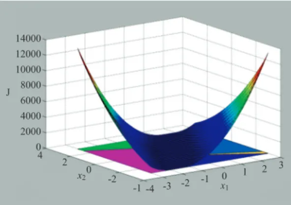
The optimal solution is a PWL function with 7 polyhedral regions and the cost function on these regions is shown in Figure. 2. The efficiency of this solution can be evaluated through a study where the
command forces are simulated as two sine wave signals. Figure. 3 shows command forces and actual forces produced from 3 actuators. Although the actuator is constrained about the power supply to the system, the errors between actual and commanded forces are almost eliminated.
RESULT AND DISCUSSION A dynamic positioning of a vessel by using assistant of 4 tugboats is studied. To counteract the effect of environmental disturbances, 4 tugboats produce thrusts simultaneously. The motion of the vessel is restricted in an area as small as possible.
Because the tugboat cannot immediately change thrust from pushing to pulling and inversely, we
Fig. 3. Comparison between actual and commanded forces.Fig. 2. Cost function through 7 polyhedral regions.
14000 12000 10000 8000 6000 4000 2000 04
2 0
-2 -1 -4 -3 -2 -1 0 x1
x2
J
1 2 3
0.5
0
-0.50.5
0
-0.50 10 20 30 40 50 60 70 80 90 100 Time (s)
Commanded data Actual data x1x2
will limit the tugboat thrust as limited pushing force to the vessel. The total system is shown in Figure. 4 and the system dynamic can be presented by the following model
h˙〓R (j) n, (22)
Mn˙ + DV〓tc
+ R
T(j) b,
where h〓[x, y, j]
T∈R
3represents the position and heading angle. n〓[u, n, r]
T∈R
3describes surge, sway and yaw rate of the ship. M, D is the inertia and damping matrix and b is the slow frequency environmental disturbance.
In this paper, the directions of tugboats are kept fixed as
3p p p 3p
a
1〓-___, a
2〓-___, a
3〓___, a
4〓 ___. (23)
4 4 4 4
The control allocation is defined in term of the forces produced by each tugboat thrust u〓(u
1,…,
u4) and the commanded force t〓(t
x, t
y, t
j). The control effectiveness matrix is calculated as follows
-0.701 0.7071 0.7071 -0.7071
B〓[ 0.7071 0.1838 -0.1838 0.1838 -0.1838 0.7071 -0.7071 -0.7071 ] . (24)
And the tugboat thrust is limited as
0≤u
i≤1 (i〓1, …, 4). (25)
In this study, the robust controller presented in the reference (Ji et al., 2013) is applied. It can capture the change of environmental disturbance, and the vessel presented good performance as shown in Figure. 5. Although, environmental disturbance gradually increases, the vessel is still kept in a small area where the change is about ± 50mm in lateral dimension and ±20mm in longitudinal dimension.
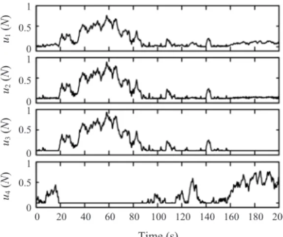
The efficiency of the mp-QP method can be evaluated based on Figures. (6) and (7). The optimal solution for this constrained control allocation is a PWL function with 61polyhedral regions. It is pre-computed and applied to this dynamic positioning simulation through a lookup table to save computing time. The 4 tugboat thrusts distributed from the commanded signals are shown in Figure. 6. It satisfies about the limited pushing force. And the error between total forces produced from 4 tugboats and forces produced from controller are almost eliminated by using mp-QP algorithm. As shown in Figure. 7, they are almost indistinguishable.
CONCLUSIONS
In this paper, we suggested an optimal approach
for solving linear constrained control allocation
problem by using mp-QP method. We have shown
that the results for this problem is a PWL function
of generalized forces and constrain limits. It can be
pre-computed and applied to real-time system by
using the lookup table technique. The efficiency of
the mp-QP method has also been evaluated by
vesselcontrol example where we try to keep the
position and orient of the barge at constant under
Fig. 4. Controlled system by using 4 tugboats.environmental disturbance by using pushing forces produced from 4 tugboats.
ACKNOWLEDGMENT
This research was supported by Basic Science Research Program funded by the Ministry of Education, Science and Technology (2012R1A1A 2039012). Also this is the part of project titled
“The development of a mooring position control system for offshore accommodation barge”funded by Ministry of Land, Transport and Maritime Affairs, Korea.
REFERENCES
Baotic M. 2002. An efficient algorithm for multi- parametric quadratic programming. Technical Report AUT02-04. http://control.ethz.ch/~ ?hybrid.
Accessed 5 Aug 2012.
Bemporad A, Morari M, Dua V and Pistikopoulos EN.
2002. The explicit linear quadratic regulator for constrained systems. Automatica 38, 3-20.
Fossen TI and Johansen TA. 2006. A survey of control allocation methods for ships and underwater vehicles. Proc Int Con Con Auto, 1-6.
Ji SW, Bui VP, Balachandran B and Kim YB. 2013.
Robust control allocation design for marine vessel.
Ocean Eng 63, 105-111.
Johansen TA. 2004. Optimizing nonlinear control allocation. Proc Con Dec Con, 3435-3440.
Johansen TA, Fossen TI and Berge SP. 2004.
Constrained nonlinear control allocation with singularity avoidance using sequential quadratic programming. IEEE Tran Con Sys Tech 12, 211- 216.
Johansen TA, Fossen TI and Tondel P. 2005. Efficient optimal constrained control allocation via multi- parametric programming. J Guid Con Dyn 28, 506
-515.
Kvasnica M, Grieder P and Baotic M. 2004. Multi- parametric toolbox (MPT). http://control.ee.ethz.ch Fig. 5. Dynamic positioning of the vessel under
environmental disturbance by using 4 tugboats.
0.02 0.015 0.01 0.005 0 -0.005 -0.01 -0.015 -0.02 -0.025
-0.05 -0.04 -0.03 -0.02 -0.01 0 0.01 0.02 0.03 0.04 0.05 Y directio (m)
X direction (m)
Fig. 6. Pushing thrusts from 4 tugboats.
0 20 40 60 80 100 120 140 160 180 200 1
0.5 01
0.5 01
0.5 01
0.5 0
Time (s) u4(N)u3(N)u2(N)u1(N)
Fig. 7. Force comparison: solid lines depict forces commanded by the controller and dash lines present actual thrusts produced by 4 tugboats.
0 20 40 60 80 100 120 140 160 180 200 1
0
-11
0.5 0 -0.50.2
0
-0.2
Time (s) tx(N)ty(N)tN(Nm)
Commanded data Actual data
/~mpt. Accessed 10 Aug 2012.
Lindfors I. 1993. Thrust allocation methods for the dynamic positioning system. Proc 10thInt Ship Con Symp, 93-06.
Sordalen OJ. 1997. Optimal thrust allocation for marine vessels. Con Eng Prac 5, 1223-1231.
Tondel P, Johansen TA and Bemporad A. An algorithm for multi-parametric quadratic programming and explicit MPC solutions. Automatica 39. 489-497.