CAE 기법을 활용한 심해 내압구조물의 최적설계에 관한 연구
정 한 구1†․팡가니반 헨리2
1군산대학교 조선공학과, 2군산대학교 기계자동차공학부
Optimal Design of Deep-Sea Pressure Hulls using CAE tools
Han Koo Jeong1† and Panganiban, Henry2
1Department of Naval Architecture, Kunsan National University, Kunsan, 573-701, Republic of Korea
2School of Mechanical and Automotive Engineering, Kunsan National University, Kunsan, 573-701, Republic of Korea
Abstract
Geometric configurations such as hull shape, wall thickness, stiffener layout, and type of construction materials are the key factors influencing the structural performance of pressure hulls. Traditional theoretical approach provides quick and acceptable solutions for the design of pressure hulls within specific geometric configuration and material. In this paper, alternative approaches that can be used to obtain optimal geometric shape, wall thickness, construction material configuration and stiffener layout of a pressure hull are presented. CAE(Computer Aided Engineering) based design optimization tools are utilized in order to obtain the required structural responses and optimal design parameters. Optimal elliptical meridional profile is determined for a cylindrical pressure hull design using metamodel-based optimization technique implemented in a fully-integrated parametric modeler-CAE platform in ANSYS. While the optimal composite laminate layup and the design of ring stiffener for a thin-walled pressure hull are obtained using gradient-based optimization method in OptiStruct. It is noted that the proposed alternative approaches are potentially effective for pressure hull design.
Keywords : deep-sea environment, pressure hull, CAE based optimization, optimal shape/thickness/stiffening, buckling constraint
†Corresponding author:
Tel: +82-63-469-1853; E-mail: [email protected] Received November 5 2012; Revised December 17 2012;
Accepted December 18 2012
Ⓒ 2012 by Computational Structural Engineering Institute of Korea
This is an Open-Access article distributed under the terms of the Creative Commons Attribution Non-Commercial License(http://creativecommons.
org/licenses/by-nc/3.0) which permits unrestricted non-commercial use, distribution, and reproduction in any medium, provided the original work is properly cited.
1. Introduction
Pressure hulls are assembled by curved shell structures in order to withstand the compressive forces induced by extremely high hydrostatic pressure in deep-sea environment. The enforced shell structures are designed to provide the shelter for manned submersible vessels and the enclosure for electronic devices, batteries, and equipments of autonomous underwater vehicles(AUVs). The design methodo- logies and construction processes of pressure hulls have been discussed by many studies(Joung et al., 2008). Both geometric configurations of pressure
hulls(i.e. hull shape, stiffener layout and wall thickness) and type of construction materials have been considered as the main parameters influencing the structural safety of pressure hulls(Bagheri et al., 2011; Barski and Kruzelecki, 2005; Cartie et al., 2006). Primitive shapes of spheres, cones, ellipsoids and combinations of them have been widely used to define the external shape of pressure hulls. High tensile strength steel, titanium alloys, aluminum alloys and composite materials are also selected to construct the hull structures. A classical design approach determines the shell thickness to meet the structural safety only after the hull shape
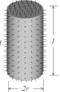
Fig. 1 Straight shell cylindrical pressure hull with end caps under uniform external pressure
and material are decided. In the case of metallic straight cylindrical pressure hull with specified diameter and length, a handy theoretical formula (Young and Budynas, 2002) can be used to deter- mine the wall thickness of the pressure vessel under the prescribed collapse pressure capacity and factor of safety. However, this approach is limited in scope. For instance, it is noted that the formula is only accurate for isotropic elastic material and at points away from the cylinder end supports or end cap joints. When composite materials are consi- dered, stresses near the end supports and cap joints are of particular interest. It is recommended to resort to alternative design approaches such as the finite element method. To allow the selection of optimal geometric configurations and materials for constructing deep-sea pressure hulls, a more flexible and efficient design approached need to be proposed.
In this paper, alternative design approaches that can be used to obtain optimal geometric shape, wall thickness, composite material configuration and stiffener layout of a pressure hull are presented. A common feature to these approaches is the utiliza- tion of CAE based design optimization tools in which CAD tool, finite element model and optimiza- tion solvers are interactively used in order to obtain the required structural responses and optimal design parameters. Three cases are presented to illustrate how the proposed design approaches can be used for pressure hull design optimization. The first design optimization case deals with the deter- mination of the optimal ellipsoidal shape of a moderately thick cylindrical pressure hull made of Ti-6Al-4V titanium alloy. The optimization problem is formulated in a manner such that for the same buckling pressure capacity and volume of internal space, weight is reduced compared to reference design.
The second design optimization case is about fin- ding the optimal ply angle and thickness of CFRP composite pressure hull. Lastly, topology optimiza- tion is carried out to obtain the conceptual layout of stiffeners for a thin-walled pressure hull under a prescribed buckling pressure limit.
2. Reference design
Fig. 1 illustrates a straight cylindrical pressure hull subjected to uniform external hydrostatic pressure. For a metallic pressure hull with thick- walled cylinder 10, where t is the thickness of the cylinder wall, the stresses in the cylinder subjected to external pressure can be calculated using the classical formula(Young and Budynas, 2002) as follows,
2
1 2 2
o
o i
qr
r r
σ −
= − (1a)
( )
( )
2 2 2
2 2 2 2
o i
o i
qr r r
r r r
σ =− +
− (1b)
( )
( )
2 2 2
3 2 2 2
o i
o i
qr r r
r r r
σ =− −
− (1c)
where , , and are the longitudinal, circum- ferential and radial normal stresses, respectively (negative means compressive). and are the inner and outer radius of the cylinder wall, respectively and ≤ ≤ is the radius of a point of interest. Applying maximum distortion energy theory i.e. elastic failure occurs when von Mises stress reaches the yield strength of the material, the wall thickness of the cylinder for the prescribed operating hydrostatic pressure or water depth in conjunction with a factor of safety can be determined using Eq. (1). On the other
Material properties Values
Density, kg/m3 4430.0
Young’s modulus, GPa 113.8
Poisson’ ratio 0.342
Yeild strength, MPa 880.0
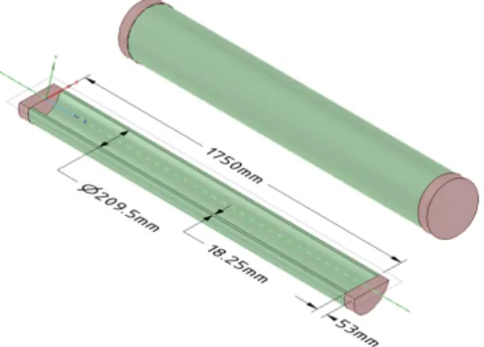
Table 1 Material properties of the reference design Fig. 2 Geometry of the reference pressure hull
Fig 3 Design parameters for shape optimization of the bowed-out pressure hull(half model)
hand, if thin-walled cylinder 10 design is desired, Eq. (1) becomes inapplicable because failure may occur due to elastic instability caused by stresses lower than elastic limit. In such case the following conventional formula can be used to calculate the required cylinder wall thickness.
( )
2 2 2 2
2 2 2 2 2
2
0.8 1 1
12 1
1 12 1
Etr n t r
q nlr n nlr r nl
π π ν
π
⎧ ⎫
⎪ ⎪
⎡ ⎤
⎪ ⎛ ⎞ ⎪
′ = + ⎜ ⎟⎛⎝ ⎞⎠ ⎨⎪⎪⎩ ⎡⎢⎢⎣ +⎛⎜⎝ ⎞⎟⎠ ⎤⎥⎥⎦ + − ⎢⎢⎣ +⎜⎝ ⎟⎠ ⎥⎥⎦ ⎬⎪⎪⎭
(2)
In Eq. (2) ′ is the external pressure at which elastic buckling occurs, is the number of lobes formed in the cylinder by buckling, is the mean radius, is the length, is the Young’s modulus, and is the Poisson’s ratio.
To provide baseline data for the verification of optimal designs presented in the following sections, thick-walled pressure hull design approaches explained in the above is applied for the design of pressure hull constructed of Ti-6Al-4V titanium alloy(Joung et al., 2008). The geometry of the pressure hull is illustrated in Fig. 2 and it is adopted as reference design. The reason for this is
to establish a reliable comparison of the optimal design results obtained using the proposed approach against published results. The rated operating pressure of the reference pressure hull is 600-bar or a dive depth of approximately 6,000m underwater.
Material properties used in the reference pressure hull are shown in Table 1.
3. Bowed-out pressure hull shape optimization
It has been shown that bowed-out or barreled pressure hulls have higher resistance to instability under compressive external hydrostatic pressure compared to the straight cylindrical design(Błachut, 2003; Jasion and Magnucki, 2007). The amount of barreling is commonly characterized by the elliptical meridional profile. For a given length and diameter of pressure hull, the optimal amount of barreling and wall thickness for specified allowable maximum stress and buckling limits can be determined.
Fig. 3 illustrates the pressure hull with elliptical bowed-out configuration. The wall thickness, (not shown in Fig. 3) and shape control parameters which are the ellipse radius in transverse direction,
, and cylinder half-length, constitute the design variables for optimization. Note that is a line segment along the radius of the ellipse in longitu- dinal direction. The shape control parameters are setup in a way that the elliptical meridional profile is free to change during the optimization process while keeping the internal diameters at the ends of the cylinder constant. This is done by using a parametric CAD tool in which the radial movement
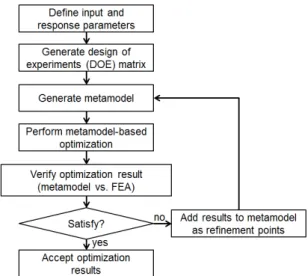
Fig. 4 Procedure of the metamodel-based design optimization
of the intersection point of elliptical curve and the end cap is constrained. The radius in longitudinal direction of the ellipse changes accordingly with and/or .
The optimal , and of the bowed-out pressure hull design are determined using metamodel-based optimization technique implemented in a fully- integrated CAE platform in ANSYS Workbench.
One-eighth of the full geometry is discretized by shell elements to take advantage of the symmetry and reduce computation. It should be mentioned that the end caps design is not considered at this point.
However, the end caps are included in FE model to simulate the axial compression due to external hydrostatic pressure.
When all design and response parameters are identified, the parametric geometry which automa- tically updates at every change in the design varia- bles is established and the rest of the processes from design of experiment(DOE) generation to the execution of the optimization solver are done without manual intervention. The metamodel-based optimi- zation results are verified with the actual FEA. If significant difference is observed, the candidate design is added as refinement points in the metamodel.
The metamodel is updated and the optimization solver is re-executed. The process is repeated until acceptable agreement between optimization and FEA
results is achieved. This metamodel-based design optimization procedure is illustrated in Fig. 4.
The main goal of shape optimization is to deter- mine the lightest bowed-out pressure hull with constraint on the buckling capacity and internal volume. Hence, the optimization problem is formulated as,
Minimize : f R L t( , , )=weight
Subject to : g R L t1( , , )=λ*≥λref (3)
( ) *
2 , , ref
g R L t =V ≥V 120≤≤300mm 115≤≤875mm 10≤ ≤60mm
where the objective function is the total weight of the pressure hull, and are the minimum buckling multiplication factors for optimal and reference pressure hull designs, respectively. and are the internal volume of the optimal and reference designs, respectively.
The selection of sufficient sample size that can be used to obtain the required information in an efficient way plays a critical role for the design of experiments. With experiments involving time- consuming runs of computer codes, it is highly desirable to have a minimal sample size that enables efficient exploration of the space of design or input parameters. By adopting a theoretically and practically proven rule for selecting sample size i.e. 10 times the number of inputs or design variables(Lee et al., 2012; Loeppky et al., 2009), an optimal space-filling design of 30 experiments is generated.
One of the reasons for using metamodel-based optimization method(Fig. 4) in this study is the possibility of obtaining global optimal design solution.
To allow such possibility, Kriging method which is known for its ability to build accurate global appr- oximation of the design space(Simpson et al., 2001) is used to build the metamodel. Moreover, the multi-objective genetic algorithm(MOGA) which is an optimization method that can obtain optimal
Property Reference Bowed-out Remarks
Weight, kg 123.5 115.8 -6.23%
Internal volume, mm3 7.54E+06 7.55E+06 Satisfied
Buckling factor 2.2 2.2 Satisfied
VM stress, MPa 481.1 498.5 +3.6%
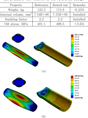
Table 2 Structural characteristics of the optimal bowed- out pressure hull relative to the reference design Fig. 5 Optimal shape of the bowed-out pressure hull
(a)
(b)
Fig. 6 First buckling mode shape(left) and von Mises stresses(right) for (a) reference design and (b) optimal
bowed-out pressure hull design
Material properties Values
Longitudinal modulus, 156GPa Transverse modulus, 9.65GPa
Poisson’s ratio, 0.27
Shear modulus, 5.47GPa
Shear modulus, 2.8GPa
Shear modulus, 3.92GPa
Density, 1580kg/m3
Longitudinal tensile strength, 1.24GPa Longitudinal compressive strength, 1.24GPa Transverse tensile strength, 41MPa Transverse compressive strength, 170MPa
In-plane shear strength, 80MPa Interlaminar shear strength, 80MPa Table 3 Material properties of Carbon/Epoxy laminated
composite material(Nexcoms, 2012) solution is also used. Note that Eq. (3) can be
treated as a multi-objective optimization problem wherein the constraints are actually objectives with lower and/or upper bounds. Fig. 5 shows the optimal shape of the bowed-out pressure hull obtained using the method pointed out above. As stated in the optimization problem in Eq. (3), although the optimal design has the same internal volume and buckling pressure as the reference
design, the optimal bowed-out pressure hull weighs over 6% lighter than the reference design with a small trade off(3.6% increase) for maximum von Mises stress. The results are summarized in Table 2. Fig. 6 shows the first buckling mode and stresses using 3D solid elements for both designs. Noting the yield strength of the material, see Table 1, the higher stress in the optimal bowed-out pressure hull compared with that of the reference design appears to have insignificant effect i.e. a factor of safety is only reduced by 5%.
4. Composite material optimization
The high stiffness to weight ratios of composite materials have been very appealing to pressure hull designers. In deep-sea application the significant reduction in weight can enable the use of thicker pressure hull wall for increased dive depth, larger propulsion system for increased speed and increased payload. CFRP and GFRP seem to be the most attractive composite materials for underwater application and have been explored in numerous studies(Cagdas and Adali, 2011; Cai et al., 2011;
Moon et al., 2010). As an alternative to the design optimization method presented in the previous section, Carbon/Epoxy laminated composite material is used for the reference straight cylindrical pressure hull replacing Ti-6Al-4V titanium alloy in order to
Fig. 7 Layered composite structure with ply thickness and angle of orientation
Layer (mm) (o) Layer (mm) (o)
1 0.3 -15 21 0.3 -45
2 0.3 90 22 0.3 90
3 0.3 -15 23 0.2 -45
4 0.3 60 24 0.3 90
5 0.3 -45 25 0.3 -45
6 0.5 60 26 0.4 75
7 0.2 -45 27 0.2 -45
8 0.3 75 28 0.3 75
9 0.3 -45 29 0.2 -45
10 0.4 75 30 0.3 45
11 0.2 -30 31 0.2 -30
12 0.4 45 32 0.4 45
13 0.2 -45 33 0.4 -30
14 0.4 75 34 0.3 45
15 0.3 -45 35 0.3 -45
16 0.3 75 36 0.3 45
17 0.2 -30 37 0.3 -45
18 0.3 90 38 0.5 15
19 0.2 -30 39 0.3 45
20 0.3 90 40 0.4 0
41-80 Symmetric
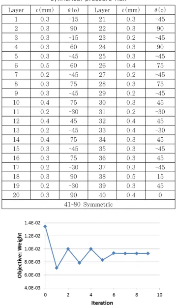
Table 4 Optimal layup of the CFRP for the straight cylindrical pressure hull
Fig. 8 Iteration history for CFRP layup optimization achieve a more significant weight reduction under
the prescribed structural performance constraints.
The CFRP material properties used in this study are shown in Table 3.
Angle of orientation of uni-directional ply can be specifically configured to achieve the desired struc- tural performance. In this study, the simultaneous consideration of ply thickness, and angle of orientation for a straight cylindrical pressure hull (see Fig. 7) during design optimization process is proposed. Classical laminated plate theory is used to calculate the stiffness and mass density of the layered composite structure and they are, subse- quently, used for the finite element analysis. Using stress and strain results from the FE analysis, failure index of each ply is evaluated based on Hill failure criterion which can be expressed as follows,
2 2 2
1 1 2 2 12
2
c c c
F X X Y S
σ σ σ σ τ
=⎛ ⎞ − +⎛ ⎞ ⎛ ⎞+
⎜ ⎟
⎜ ⎟ ⎜ ⎟ ⎝ ⎠
⎝ ⎠ ⎝ ⎠ (4)
where and are longitudinal and transverse stresses. Optistruct(OptiStruct), which performs the automatic calculation of the required composite material parameters, is used for the design optimi- zation of straight cylindrical pressure hull constructed of CRFP.
The goal of the CFRP optimization is to obtain the lightest straight cylindrical pressure hull design with at least the same buckling factor as the reference design. Additionally, ply failure must not occur. Based on the experience during simulation, 20% mass reduction can be assumed at the begin-
ning of optimization(iteration 0). That is, at a maximum thickness of 0.5mm per layer(number of plies laid with the same angle of orientation to achieve this thickness) and the density ratio between titanium alloy and CFRP 20% initial mass reduc- tion requires only 80 plies to obtain reasonable and acceptable results. Symmetry in ply stacking sequences is assumed. Thus 40 design variables for ply thick- ness and angle of orientation are considered. Discrete values for ply thickness and angle of orientation are assigned to improve the manufacturability of the optimal design. The optimization problem is formulated as,
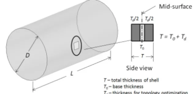
Fig. 9 Shell structure with non-zero base thickness model for topology optimization with buckling
constraint
(a) Topology optimization iteration
(b) First buckling mode shapes of reference design(left) and optimal design(right)
(c) Solid remodeling and FEA verification Fig. 10 Stiffener topology optimization results Minimize : f t( ),θ =weight
Subject to : g t1( ),θ =λ*≥λref (5)
2( ), 1.0
g tθ = ≤F
{0.1, 0.2, 0.3, 0.4, 0.5}mm t∈
{ 75, 60 45, 30, 15, 0,15, 30, 45, 60, 75, 90}
θ∈ − − − − − o
The optimal stacking sequence of the CFRP for the straight cylindrical pressure hull design is summarized in Table 4. The total wall thickness is 24.4mm which implies 33% thickness increment than the reference design case. However, the weight of the pressure hull is reduced by 38% with the buckling and ply failure constraints satisfied. The CFRP optimization iteration plot is shown in Fig. 8.
5. Stiffener design using topology optimization
Topology optimization is a method of finding the best layout of a limited amount of material over the given design domain in a structure subjected to certain loading and support conditions. The structure resulting from topology optimization usually requires designer’s interpretation for post-processing into realistic layout. This method is commonly used to obtain quick concept design of structures for various applications(Jang et al., 2010; Kim et al., 2010).
While the structural topology of fixed-section stiff- eners for thin-walled marine structures can be efficiently designed using other methods such as the sequential quadratic programming(Jeong, 2010), in this work, the optimal layout of ring stiffeners for a thin-walled pressure hull is obtained using topology optimization method available in OptiStruct. The method practically enables more freedom for stiffener layout in contrast to conventional approach which often utilizes fixed structural form. As an initial or reference design, unstiffened straight cylindrical pressure hull with the thickness of 5mm is established using the theoretical formula Eq. (1) and Eq. (2). Standard optimization objective is to maximize the minimum buckling pressure subject to weight constraint. However, convergence difficulty
was experienced by using the standard formulation.
Hence, an alternative formulation shown in (6) is used instead. Similar results can be obtained by increasing the lower limit of buckling pressure constraint and making sure that the mass does not exceed that of the reference design.
Minimize : f( )x =x VT
Subject to : g
( )
x =λ*≥λref (6)( )
L U
=
≤ ≤ K x u f x x x
Since buckling constraint is involved, the topology optimization of shell structure with non-zero base thickness approach in particular is used to avoid the phenomenon called singular topology(Zhou, 2004).
Base thickness out of the total thickness of the shell structure is non-designable. Thus, the shell structure does not become totally void avoiding singular topology throughout the optimization process.
The shell structure model used for topology optimi- zation of stiffener of a thin-walled pressure hull is illustrated in Fig. 9.
To promote better interpretation of the optimal topology while taking advantage of symmetry, a half geometry model is considered. This model has the inner diameter of 100mm, the length of 400mm, the total thickness of 10mm, the base thickness of 3 mm and the stiffener net thickness of 7mm, respec- tively. Fig. 10 shows the optimal layout of stiffe- ners for the thin-walled pressure hull design. The shift of the lowest buckling mode is obvious. With the same weight as 5mm thick reference cylindrical pressure hull, 3mm thick pressure hull with optimal stiffener size and layout has increased the buckling pressure capacity by 35%.
6. Conclusions
Alternative approaches that can be used to obtain optimal geometric shape, wall thickness, composite material configuration and stiffener layout of a pressure hull are presented. These approaches underscore the use of CAE based design optimiza- tion tools. Optimal elliptical meridional profile is determined for a cylindrical pressure hull design using metamodel-based optimization technique imple- mented in a fully integrated parametric modeler- CAE platform in ANSYS. While conceptual design of ring stiffener layout of a thin-walled pressure hull is obtained using gradient-based optimization method in OptiStruct. Optimal design for weight reduction of thick-walled pressure hull or improvement of structural performance such as the buckling capacity of thin-walled design can be effectively achieved
using the proposed CAE-based optimization tools.
Acknowledgement
This research work was supported by Surmoun- ting Technology over Maritime Extreme Environ- ment Project funded by Korea Institute of Ocean Science & Technology and also supported by Basic Science Research Program through the National Research Foundation of Korea(NRF) funded by the Ministry of Education, Science and Technology (2011-0023016). The authors would like to thank their supports.
References
ANSYS Academic Research, Release 12.1.
Bagheri, M., Jafari, A., Sadeghifar, M. (2011) Multi-Objective Optimization of Ring Stiffened Cylindrical Shells using a Genetic Algorithm, Journal of Sound and Vibration, 330, pp.374~384.
Barski, M., Kruzelecki, J. (2005) Optimal Design of Shells Against Buckling under Overall Bending and External Pressure, Thin-Walled Structures, 43, pp.1677~1698.
Błachut, J. (2003) Optimal Barreling of Steel Shells Via Simulated Annealing Algorithm, Computers and Structures, 81, pp.1941~1956.
Cagdas, I., Adali, S. (2011) Buckling of Cross-Ply Cylinders under Hydrostatic Pressure Considering Pressure Stiffness, Ocean Engineering, 38, pp.559
~569.
Cai, B., Liu, Y., Liu, Z., Tian, X., Ji, R., Li, H.
(2011) Reliability-Based Load and Resistance Factor Design of Composite Pressure Vessel under External Hydrostatic Pressure, Composite Structures, 93, pp.2844~2852.
Cartie, D., Davies, P., Peleau, M., Partridge, I.
(2006) The Influence of Hydrostatic Pressure on the Interlaminar Fracture Toughness of Carbon/
Epoxy Composites, Composites: Part B, pp.292~
300.
Jang, G.W., Yoon, M.S., Park, J.H. (2010) Light- weight Flatbed Trailer Design by using Topology and Thickness Optimization, Structural and Multidisciplinary Optimization, 41, pp.295~307.
요 지
내압구조물의 구조적 성능에 영향을 주는 주요 요소로 형상, 쉘 두께, 보강재 배치 안 그리고 제작 재료 등을 나열할 수 있다. 전통적인 이론적 방법론에 근거한 내압구조물의 설계는 신속하며 만족할 만한 결과를 제공하지만 이는 일부 특정한 형상, 쉘 두께 및 제작 재료 등에 제한되어 있다. 본 논문에서는 최적화된 형상, 쉘 두께, 보강재 배치 안 그리고 복합재료 적 층 정보 등을 얻을 수 있는 최적설계 기법에 근거한 진보된 대체 방법론을 다루고 있다. CAE 기반의 최적설계 기법을 활용 하여 내압구조물 설계에 요구되는 구조적 성능과 최적화된 설계 인자들을 얻었다. 상용화된 유한요소 프로그램임 ANSYS의 CAE 플랫폼으로부터 메타모델 기반 최적화 기법을 수행하여 원통형 내압구조물의 설계를 위한 최적의 타원형 형상을 결정 하였다. 또한 최적설계 프로그램인 OptiStruct의 기울기 기반 최적설계 방법을 이용하여 복합재료 기반 내압구조물의 설계 시 최적의 적층순서와 쉘 두께가 얇은 내압구조물에 대한 최적의 보강재 배치 안을 각각 도출하였다. 최적설계 예제를 통해 본 논문에서 제시하고 있는 최적설계 기법에 근거한 방법론이 내압구조물의 설계에 효과적임을 확인할 수 있었다.
핵심용어 : 심해 환경, 내압구조물, CAE기반 최적화, 최적화된 형상/두께/보강, 좌굴 제한조건 Jasion, P., Magnucki, K. (2007) Elastic Buckling
of Barrelled Shell under External Pressure, Thin- Walled Structures, 45, pp.393~399.
Jeong, H.K. (2010) Comparative Study of Metallic and Non-Metallic Stiffened Plates in Marine Structures, Journal of the Computational Stru- ctural Engineering, 23, pp.715 ~726.
Joung, T.-H., Lee, J.-H., Nho, I.-S., Lee, C.-M., Lee, P.-M., Aoki, T., Hyakudome, T. (2008) A Study on the Pressure Vessel Design, Structural Analysis and Pressure Test of a 6000m Depth- Rated Unmanned Underwater Vehicle, Ships and Offshore Structures, 3, pp.205~214.
Kim, M.G., Kim, J.H., Cho, S. (2010) Topology Design Optimization of Heat Conduction Problems using Adjoint Sensitivity Analysis Method, Journal of the Computational Structural Engineering, 23, pp.683~691.
Lee, G., Park, J., Choi, D.-H. (2012) Shape Optimization of Mobile Phone Folder Module for Structural Strength, Journal of Mechanical Science and Technology, 26, pp.509~515.
Loeppky, J.L., Sacks, J., Welch, W.J. (2009)
Choosing the Sample Size of a Computer Experi- ment: A Practical Guide, Technometrics, 51, pp.366~376.
Moon, C., Kim, I., Choi, B., Kweon, J., Choi, J.
(2010) Buckling of Filament-Wound Composite Cylinders Subjected to Hydrostatic Pressure for Underwater Vehicle Applications, Composite Struc- tures, 92, pp.2241~2251.
Nexcoms Co., Ltd. (2012) Material Property Testing of a Group of CFRP Laminates.
OptiStruct. Altair HyperWorks, Version 11.0.
Simpson, T.W., Mauery, T.M., Korte, J.J., Mistree, F. (2001) Kriging Models for Global Approximation in Simulation-Based Multidisciplinary Design Optimization, AIAA Journal, 39, pp.2233~
2241.
Young, W.C., Budynas, R.G. (2002) Roark's Formulas for Stress and Strain, Seventh ed, McGraw-Hill, New York.
Zhou, M. (2004) Topology Optimization for Shell Structures with Linear Buckling Responses, Compu- tational Mechanics, WCCM VI, Tsinghua University Press & Springer Verlag, Beijing, China.