Vol. 63, No. 2, February 2013, pp. 143∼145
New Physics: Sae Mulli, DOI: 10.3938/NPSM.63.143
Polarized 129 Xe Production by Using the Spin Exchange Optical Pumping Method
S. Chebotaryov · W. Kim ∗ · E. Milman · S. Stepanyan
Kyungpook National University, Daegu 702-701, Korea (Received 10 December 2012 : accepted 4 February 2013)
Polarized
129Xe can be used as a gaseous contrast agent for medical resonance imaging (MRI) and which provides better resolution to evaluate lung and other body tissues in vivo. We are developing a setup for
129Xe gas polarization based on the optical-pumping spin-exchange method. The system can produce high quantities of highly-polarized
129Xe atoms and consist of Helmholtz solenoid coils, a high-power diode laser, the optical elements for forming the circularly-polarized laser beam, and
“Apollo” nuclear magnetic resonance (NMR) system for measuring the
129Xe polarization level and a vacuum handling system. In this article, we will discuss the current status of our setup.
PACS numbers: 21.10.Hw
Keywords: Polarized
129Xe, Optical pumping, NMR
I. Introduction
Initially hyperpolarized
129Xe was developed and used for the purposes of fundamental studies in nuclear physics. However the most recent use is implementa- tion of the hyperpolarized gases as imaging agents in the medical resonance imaging (MRI). Polarized
129Xe can serve as a gaseous contrast agent for MRI. It provides new ways to evaluate lungs and other body tissues in vivo. Has multiple advantages over
3He despite its lower gyro-magnetic ratio or lower spin-lattice relaxation time.
Its natural abundance with no limitation on its supply, has a very low price, and has a high solubility offering dissolved MRI possibilities.
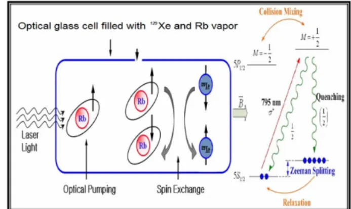
129Xe polarizer is based on spin-exchange optical pumping (SEOP) method. In this method typically the transfer of the angular momentum from the polarized laser photon to the noble-gas nuclei is intermediated by an alkali metal vapor. It is based on polarizing the valence electron of the alkali metal by resonant absorption of the laser light, enhancing a sin- gle state of the ground level. Schematic presentation of polarization method is shown on Fig. 1.
∗
E-mail: [email protected]
Fig. 1. (Color online)
129Xe polarization scheme.
On the Fig. 2 an example of conventional MRI and MRI with polarized gas is shown. Conventional MRI gives good results with water-filled solid tissues, but does a poor job of imaging body cavities. These cavities, such as the interiors of the lungs, appear as dark voids in conventional MRI. Employing polarized noble gases in MRI technology, greatly improves MRI resolution over such regions. When an organ such as a lung is filled with laser-polarized noble gas and scanned via MRI, the gas physical properties help generate highly detailed, images.
143
144 New Physics: Sae Mulli, Vol. 63, No. 2, February 2013
Fig. 2. (Color online) MRI with polarized gazes.
II. Experimental Method and Setup
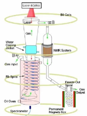
In our system the idea of counter flowing the optical pumping gas mixture against the laser light is used. On the Fig. 3 overall scheme of the polarizer setup is shown.
The polarizer can be described in terms of three different operational regions [2]:
- rubidium saturation region (spiral),
- laser absorption and polarizing region (straight- tube),
- rubidium condensing region (water cooling jacket)
The spiral region of the polarizer where Rb is heated to the temperature of 160
◦C. This is required in order to generate optically-thick alkali metal vapor. A mixture of gases: N
2+
4He +
129Xe, nitrogen with the purpose of radiation quenching, and a buffer gas for pressure broad- ening of the alkali absorption line are introduced into the system at the “Gas Input”, then the mixture trav- els through the spiral region - its purpose is to offer a long path for the entering gas mixture to reach the oven temperature and to saturate the gas mixture with Rb vapor before entering the main column. The polarizer is placed inside uniform low magnetic field for Zeeman splitting the Rb atom energy levels. The gas mixture saturated with Rb vapor, moves from the spiral into the optical pumping region. The polarization process starts at the beginning of the straight-tube region, with the optical pumping mixture being illuminated with attenu- ated laser light, and progresses as it moves towards the
Fig. 3. (Color online)
129Xe polarizer scheme.
highly illuminated region of the cell. The highest polar- ization level is expected to be attained in the top few centimetres of the hot region, where most of the laser light is absorbed.
The water cooling jacket is for cooling of the gas mx- ture, resulting in Rb condensation on the walls. After the Rb vapor is removed, the remaining gas mixture, in- cluding the hyperpolarized xenon, exits the polarizer and travels through NMR coils setup for polarization mea- surement and after this passes into the freeze-out system for xenon accumulation where it can be frozen and sep- arated from other gases.
1. Laser and Optical System
It is essential to have effective optical pumping of al- kali metal vapours for the overall polarization to be suc- cessful. The high power diode lasers offer an excellent source of light for alkali optical pumping applications.
Continuous-wave diode lasers are commonly used in op-
tical pumping because of their high power, compact-
ness, and low cost. The laser wavelength corresponds
to the D1 absorption line of the alkali metal, e.g., 794.7
Polarized
129Xe Production by Using the Spin Exchange Optical Pumping Method – S. Chebotaryov et al. 145
Fig. 4. (Color online) Optical system scheme.
Fig. 5. (Color online) NMR pick-up and drive coils.
nm for Rb. Diode laser emission profile has typically a Lorentzian shape with a FWHM of 1.5 - 2 nm.
Optical setup consists from a high power diode laser with standard SMA-905 optic connector for coupling and transport of the beam through optics fiber and light po- larizing components. The laser light on the end of fiber optic becomes unpolarized. Therefore the optical com- ponents have the purpose of shaping the laser beam and transforming it into circularly polarized light. A typical optical setup used with lasers fiber-coupled is shown in Fig. 4. The polarizing cube splitter divides the beam into two linearly-polarized halves with orthogonal polariza- tion planes. Finally, two quarter-wave-plates transform the linear polarized light into circular polarized light and the beam is directed to towards
129Xe polarizer.
2. NMR Signal Measurement
129