제16권, 제3호. pp.180-191, 2016
정전위 전해식 가스센서의 가속수명시험법 개발
양일영
1⋅강준구
1⋅유상우
1⋅오근태
2⋅나윤균
2†1
한국산업기술시험원,
2수원대학교 산업정보공학과
Development of Accelerated Life Test Method for Constant Electrical Potential Electrolysis Gas Sensor
Il Young Yang
1ㆍJun Gu Kang
1ㆍSang Woo Yu
1ㆍGeun Tae Oh
2ㆍYoon Gyoon Na
2†1
Korea Testing Laboratory,
2The University of Suwon
Purpose: The purpose of this study was to develop the accelerated life test method for Constant
Electrical Potential Electrolysis gas sensor (CEPE gas sensor).
Methods: The parts and modules of CEPE gas sensor were analyzed by using Reliability Block
Diagram (RBD). Failure Mode and Effect Analysis (FMEA) and Quality Function Deployment (QFD) methods were performed for each part to determine the most affecting stress factor in its life cycle. The long term testing was conducted at three different dry heat levels and the acceleration factor was developed by using Arrhenius relationship.
Conclusion: The acceleration factor for CEPE gas sensor was developed by using FMEA, QFD,
and statistical analysis for its failure data. Also qualification tests were designed to meet the target life.
1)
Keywords: Constant Electrical Potential Electrolysis Gas Sensor, Failure Mode and Effects
Analysis, QFD, Acceleration Factor
1. 서 론
근래 각종 가스가 에너지원으로 이용되기 시작하 면서 대기 중에 존재하는 유해가스 및 대기오염 물질 이 다량으로 축적되고 있기 때문에 공업 분야는 물론 가정용으로도 이러한 가스를 검출하는 방법에 대한 수요가 높아지고 있다. 가스센서는 대기 중에 존재하 는 유해가스 및 대기오염 물질을 정량적으로 측정하 기 위한 가스 측정기의 핵심 부품 중 하나로 안전, 환 경, 에너지, 가전, 의료, 국방 분야 등 다양한 분야에 폭넓게 적용되고 있다. 특히 가스센서는 독성 가스용
으로 불산(HF), 일산화탄소(CO), 염소(Cl
2), 황화수소 (H
2S) 센서 등이 있으며 대기오염 물질 측정용으로 이 산화황(SO
2), 이산화질소(NO
2)센서 등이 있다.
가스센서를 구분하기 위해 정용근[2]은 가스센서 를 크게 가스의 흡․탈착 현상을 이용한 센서와 가스 의 반응성을 이용한 센서로 구분하였다. 또한 흡․탈 착에 의한 센서는 반도체식 가스센서와 표면 전위형 가스센서로 세분하고 반응성을 이용한 센서로는 접 촉 연소식 가스센서와 정전위 전해식 가스센서로 세 분하였다. 가스센서의 특성으로 박상열 외[9]는 정전 위 전해식 가스센서를 다른 가스센서에 비해 정밀도,
†교신저자 [email protected]
2016년 7월 6일 접수; 2016년 7월 15일 수정본 접수; 2016년 7월 28일 게재 확정.
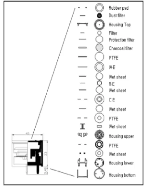
Fig. 1 Component of CEPE gas sensor
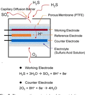
Fig. 2 Structure of CEPE gas sensor
안정성, 수명 등의 측면에서는 다소 뒤지지만 고감도
로서 소형, 경량화가 가능하고 저렴하기 때문에 독성 가스 검지용으로 많이 이용됨을 언급하였다. 이처럼 정전위 전해식 가스센서는 사람의 안전과 직접적으 로 연결되어 있는 유해 가스 검지를 주목적으로 사용 되기 때문에 높은 신뢰성이 요구되고 있다.
가스센서 관련된 기존 가속수명시험법이 개발된 사례가 있다. 김종걸 외[4]는 가스기기 안전장치 및 조리 기구에 사용되는 가스센서 구성 요소 중 Heater 를 핵심 부품으로 파악하고 온도에 의한 아레니우스 모델, 전압에 의한 아이링 모델의 복합 스트레스에 의 한 가속시험법을 제안하였다. 강준구 외[3]는 접촉 연 소식 가스센서의 가스 농도가 증가하면 촉매 표면의 온도 상승 및 표면 변형으로 센서의 출력이 저하되는 고장 메커니즘을 제시하였고 3수준 시험을 통해 수명 과 스트레스 관계를 추정하였다. 신뢰성 인증 표준인 RS C 0105[11]는 반도체식 가스센서의 고장메커니즘 을 3종류로 제시하고 있다. 센서 오염에 의한 출력 성 능 저하, 히터회로의 열 변형으로 인한 출력 저하, 진 동 및 충격에 의한 단락 단선의 메커니즘 중 전압을 주요 스트레스 인자로 보고 전압가속 모형을 통해 가 속시험법을 제안하였다.
본 연구에서는 가스센서 중 정전위 전해식 가스센 서의 가속수명시험법을 제안하였다. 가속수명시험법 개발을 위해 필요한 성능 및 고장 판정기준을 수립하 였고, 성능 및 신뢰성에 영향을 미치는 스트레스 인자 를 도출하기 위해 신뢰성 블록 다이어그램, FMEA, QFD 등의 방법을 활용하였다. 주요 스트레스 인자를 고온으로 보고 3수준 시험을 통해 가속계수를 도출하 였고 목표 수명을 보증하기 위한 시험계획을 수립하 였다.
2. 정전위 전해식 가스센서
2.1 정전위 전해식 가스센서의 구성요소 분해 정전위 전해식 가스센서(Constant Electrical Potential Electrolysis gas sensor, CEPE gas sensor)의 주요 고장 모 드 및 메커니즘을 파악하기 위해 대상 부품의 구조를 분 석할 필요가 있다. 정전위 전해식 가스센서의 주요 구성 요소와 사용된 부품의 종류는 <Fig. 1>과 같다.
전기 화학적 방식인 정전위 전해식 가스센서의 핵 심 부품은 전극, Current collector, 전해질(Electrolyte) 로 볼 수 있다. 또한 전극은 작용전극(Working elec- trode), 기준전극(Reference electrode), 대전극(Counter electrode)으로 구분 할 수 있고 이를 단면으로 구조화 해서 나타내면 다음 <Fig. 2>와 같다.
2.2 정전위 전해식 가스센서의 측정원리
정전위 전해식 가스센서는 측정 대상 가스의 산화
환원 반응시에 발생하는 전자의 양을 감지하여 해당
가스의 농도를 측정한다. 그 구조는 측정물질의 산화
가 일어나는 작용전극(Working Electrode), 작용전극
에 외부로부터 전압을 걸어 줄 때 기준이 되는 기준전
극(Reference Electrode), 감응전극에서 흐르는 전류만
큼의 대응 전류를 흘려줌으로써 평형을 유지시키는
Gas type. Reaction formula Redox potential CO CO+H2O ↔ CO2+2H++2e- -0.12V SO2 SO2+2H2O ↔ SO4-2 +0.17V NO2 NO2+H2O ↔ NO3-+2H++e- +0.80V NO NO+H2O ↔ NO2+2H++2e- +0.102V
O2 O2+4H++4e- ↔ 2H2O +1.23V Table 1 Oxidation-reduction potential of
potentiometric electrolysis type sensor
Test item KS C 6566 RS C 0105, RS C 0106 CEPE gas sensor
Sensitivity (output current)
(1) Clean air, standard testing gas (2) Output current after 1 minute (3) More than 20 mV output
(1) Clean air, standard testing gas (2) Ratio of the sensor resistance
after 1 minute
(3) Less than 0.5 resistance ratio
(1) Clean air, standard testing gas (2) Sensitivity after 1 minute
(output current)
(3) Within tolerance (refer to product specifications) Reproducibility (1) Clean air, standard testing gas
(2) 5 minute interval 5 times (3) Within ±5% of the output mean
(1) Clean air, standard testing gas (2) 5 minute interval 5 times (3) Within ±5% of the output mean
(1) Clean air, standard testing gas (2) 5 minute interval 5 times (3) Within ±5% of the output mean
Time of response
(1) Clean air → standard testing (2) Time to 90% of the maximum gas
output
(3) Time of response within 20 second
(1) Clean air → standard testing (2) Time to 90% of the maximum gas
output
(3) Time of response within 20 second
(1) Clean air → standard testing (2) Time to 90% of the maximum gas
output
(3) Time of response within 20 second
Recovery time
(1) Clean air → standard testing (2) Time to 10% of the maximum gas
output
(3) Recovery time within 40 second
(1) Clean air → standard testing (2) Time to 10% of the maximum gas
output
(3) Recovery time within 40 second
(1) Clean air → standard testing (2) Time to 10% of the maximum gas
output
(3) Recovery time within 40 second
Stability Not applicable
(1) Clean air, standard testing gas (2) 60 minute continuous output
measurement
(3) Output characteristic within
±3%
Delete
(corresponding to gas detector requirements)
Withstand voltage
(1) Sine wave 60 Hz, 500 V, 1 minute
(2) Check abnormal conditions
(1) Sine wave 60 Hz, 500 V, 1 minute
(2) Check abnormal conditions Delete (non powered) Insulation
resistance (1) 500 V displayed at megger
(2) More than 500 MΩ (1) 500 V displayed at megger (2) More than 500 MΩ Delete
(non powered) Table 2 Performance of CEPE gas sensor
Fig. 3 The operation principle of the oxidation- reduction reaction
대전극으로 구성된다. 이런 전극과 전해질 계면을 일 정한 전위로 유지하면서 전해되는 작용을 한다. 이 경 우 설정 전위를 바꿈으로써 <Table 1>과 같은 특정 가 스를 선택적으로 검지한다[6].
예를 들어, 황화수소(H
2S)의 경우 <Fig. 3>과 같이
외부 가스 중에 포함된 황화수소 성분이 센서의 내부
작용전극에 확산되어 도달하면, 전극 표면에서 H
2S
가 SO
3로 산화되고, 그 결과 전자가 발생한다. 이때,
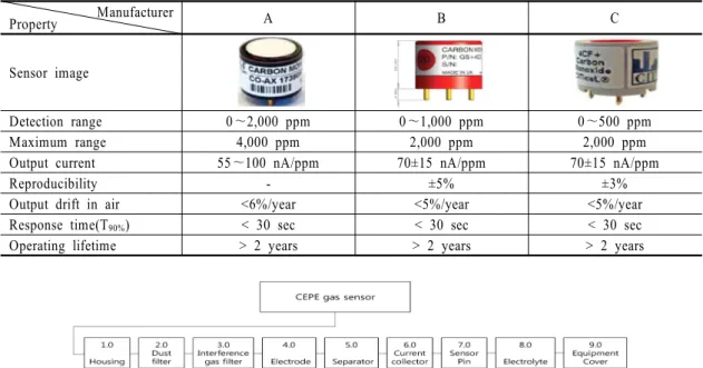
Manufacturer
Property A B C
Sensor image
Detection range 0~2,000 ppm 0~1,000 ppm 0~500 ppm
Maximum range 4,000 ppm 2,000 ppm 2,000 ppm
Output current 55~100 nA/ppm 70±15 nA/ppm 70±15 nA/ppm
Reproducibility - ±5% ±3%
Output drift in air <6%/year <5%/year <5%/year
Response time(T90%) < 30 sec < 30 sec < 30 sec
Operating lifetime > 2 years > 2 years > 2 years
Table 3 Specifications of CEPE gas sensor
Fig. 4 Reliability block diagram for CEPE gas sensor
대전극에서는 작용전극의 반응과 평형을 유지하기
위하여 공기 중에 포함된 산소를 물로 환원시키는 반 응을 수행한다. 결국, 황화수소 센서는 가스의 황화수 소 농도에 비례하는 전기적 신호(전류)를 발생하므로 이 전류를 측정하면 농도를 알 수 있게 된다.
2.3 정전위 전해식 가스센서의 성능 시험 항목 정전위 전해식 가스센서의 장기간 시간에 따른 성 능 및 신뢰성을 확인하기 위해 성능 시험 항목을 결정 해야 한다. 가스센서 관련된 기존 문헌을 참고하고, 별도의 전원이 인가되지 않는 정전위 전해식 가스센 서의 특성을 반영하여 선정한 성능 시험 항목은 다음
<Table 2>와 같다[5, 11, 12].
3. 정전위 전해식 가스센서의 가속수명시험법 개발
3.1 시험 대상 선정
가속계수 도출을 위해 해외에서 판매되는 가스센 서 중 시장 점유율이 높고 공정이 안정되었다고 알려
진 제품을 선정하였다. 각 제조사 제품 사양은 다음
<Table 3>과 같다.
3.2 신뢰성 블록 다이어그램
시스템을 구성하고 있는 부품의 기능적 관계와 상 호간의 영향을 해석하기 위해서는 ‘시스템이 성공적 인 기능 수행을 위한 경로’를 나타내는 신뢰성 블록 다이어그램 작성이 필요하다[10]. 정전위 전해식 가 스센서는 각 구성품이 직렬로 연결된 시스템으로 구 성품별 임무 및 기능별 블록을 다음 <Fig. 4>, <Table 4>와 같이 구분하였다.
3.3 FMEA 수행
정전위 전해식 가스센서에서 발생할 수 있는 잠재적
고장이 제품에 미치는 영향과 원인 및 메커니즘을 상향
(bottom-up)식으로 조사하고, 각 고장모드에 대한 위험
평가를 위해 FMEA(Failure Mode & Effect Analysis)를
수행하였다. FMEA는 가속수명시험의 발생 가능한 고
장모드 확인을 주된 목적으로 작성하였기 때문에
RPN(Risk Priority Number) 수치를 제외하고 고장모드,
No. Components Function Failure mode Probable cause Failure effect Detection
method Division
1.0 Housing
Configuring External Sensors, Electrodes
and laminated carrier guiding, Control external
reaction gas diffusion inflow
Sensor output value defective
Capillary hole machining
defects
Specifications dissatisfied
Drill dimensional
inspection, Sensors total
inspection
Quality
2.0 Dust filter Protect Capillary hole from dust and
moisture
Hole interference when Dust
cover attaching
Membrane machining
defects
Sensor output value decreases
Visual
inspection Quality
3.0 Interference
gas filter Interference gas reaction suppression
Increased interference gas influence
Insert filter contamination
Increased interference gas properties
Visual
inspection Reliability
4.0 Electrode Redox reaction of the gas
Electrode adhesion degradation
Carelessness of electrode shape processing and
transportation
Sensor output value defective
Visual
inspection Reliability
5.0 Separator
Supply passage of electrolyte between
working electrode and counter
electrode
Imbalance in the image
Separator machining
defects
Decreased sensor output
value
Visual
inspection Quality
6.0 Current collector
Delivering generated current from oxidation reaction to
the external sensor
Inability to deliver current signals
short between Sensor pin and
welding point
Sensor output value defective
Visual
inspection Reliability
7.0 Sensor pin Connecting part between device and
PCB
Electrolyte
leakage Sealing defective Sensor output value defective
Visual inspection
before assembling
Quality
8.0 Electrolyte
Transfer passage during the redox reaction of the gas
ions
Electrolyte evaporation
prolonged exposure to high
temperatures
Decreased sensor durability characteristic
Measurement output,
visual inspection
Reliability
9.0 Equipment
cover Protect product caused by shock
Dust and foreign objects inserted
Poor contact Degraded
characteristics Visual
inspection Quality
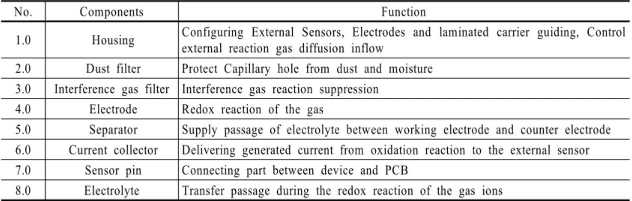
No. Components Function
1.0 Housing Configuring External Sensors, Electrodes and laminated carrier guiding, Control external reaction gas diffusion inflow
2.0 Dust filter Protect Capillary hole from dust and moisture 3.0 Interference gas filter Interference gas reaction suppression
4.0 Electrode Redox reaction of the gas
5.0 Separator Supply passage of electrolyte between working electrode and counter electrode 6.0 Current collector Delivering generated current from oxidation reaction to the external sensor 7.0 Sensor pin Connecting part between device and PCB
8.0 Electrolyte Transfer passage during the redox reaction of the gas ions Table 4 Function for each component
Table 5 FMEA for CEPE gas sensor
Test methods Failure mode(Failure mechanism)
Stress factor Dry heat Cold Thermal
shock Humidity Vibration Shock Free fall Increased interference gas influence
(insert filter contamination) △ - - ○ - - -
Electrode adhesion degradation (transportation high
temperature and mechanical environment) ○ - △ ◎ ○ ○ ○
Inability to deliver current signals
(short between Sensor pin and welding point) ○ - ○ △ - - -
Electrolyte leakage (housing and sensor pin
interface seal destruction caused by shock) - - - - - ◎ ◎
Electrolyte evaporation
(prolonged exposure to high temperatures) ◎ - - - - - -
Effect index 12 0 4 9 3 8 8
◎: Very closely, 5 point
○: Closely, 3 point
△: In effect, 1 point
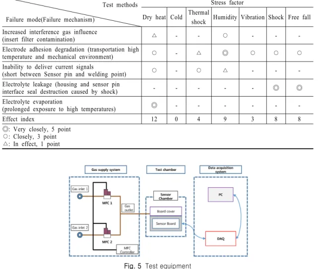
Table 6 Quality Function Deployment for each component
Fig. 5 Test equipment
고장의 원인, 영향, 검지 방법 등만 작성하여 <Table 5>
에 제시하였고, 해당 고장모드가 품질 혹은 신뢰성 문제 로 봐야 하는지 구분하였다. 구분된 품질, 신뢰성 원인 중 신뢰성 관련된 문제를 주요 스트레스 인자 도출의 고 장 모드 및 메커니즘으로 적용하였다.
3.4 주요 스트레스 인자 도출
FMEA 수행 결과 신뢰성 측면에서 접근할 고장 모 드 중 정전위 전해식 가스센서의 성능 및 신뢰성에 영 향을 미치는 스트레스 인자 도출을 위해 QFD(Quality Function Deployment)를 수행하였고, <Table 6>에 제 시되었다. 여기서 고장모드는 FMEA 수행 결과 신뢰
성 관점에서 접근할 고장모드 및 메커니즘, 스트레스 인자는 박정원 외[8]가 제시한 수명 주기 중에 노출될 수 있는 환경 요인 도출 연구를 참고하여 관련된 스트 레스 항목을 선정하였다.
주요 스트레스 인자 도출 결과 고온이 가장 큰 영향 을 미치는 인자로 선정되었고, 이와 관련된 주 고장 모드 및 메커니즘은 전해액 증발에 따른 센서 감도(출 력) 저하이다.
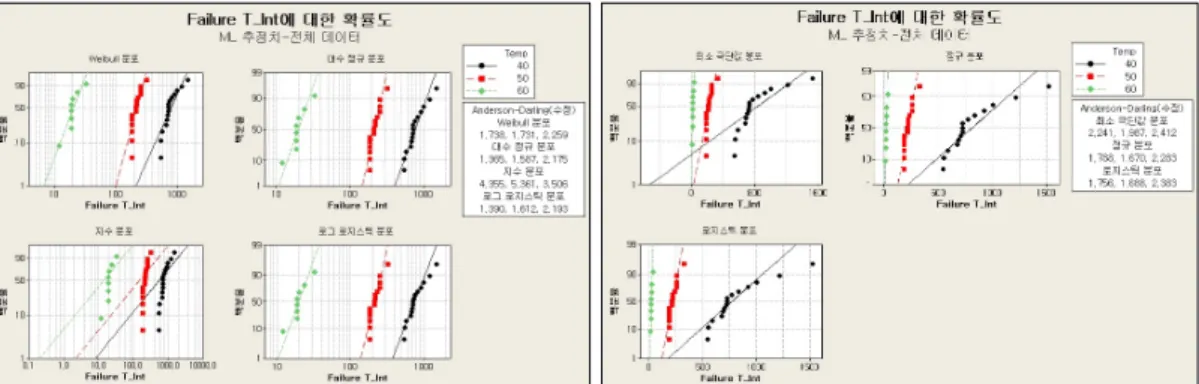
3.5 가속수명시험 시험 계획 수립 및 수행 3.5.1 시험장치 구성
고온에 의한 전해액 증발을 시간이 지남에 따라 확인
Item Specification Number of
specimen 3 type manufacturers × 3 test chambers × 5 ea = 45 ea Test chamber
volume More than 10 L for each test chamber
Test condition (dry heat)
40℃
50℃
60℃
Applied voltage -
Measurement
characteristics Sensor weight, output and output ratio
Measuring interval The initial two-week three times a week, 1 times a week after initial 2 weeks Table 7 Accelerated life test plan
(a) A sensor weight reduction ratio
(b) B sensor weight reduction ratio
(c) C sensor weight reduction ratio Fig. 6 Average weight reduction ratio
하기 위해 감도(출력)를 측정할 수 있는 장치를 미리 구
성하여야 한다. 이를 위해 표준 가스 공급을 위한 gas supply system, 고온 환경을 만들어 주는 test chamber, 감 도를 측정하기 위한 data acquisition system을 <Fig. 5>와 같이 구성하였다. 구성된 시험 장치를 통해 시험 및 측정 을 위한 장치를 구성하였고 시험 중 측정 주기에 도달했 을 때 보다 손쉽게 측정할 수 있도록 하였다.
3.5.2 시험 계획 수립
고온에 의한 3수준 시험 수행 시 시험 가능한 최고 온 도를 60℃ 로 보고 Meeker and Hanh[7]의 3수준 시험의 시험수준 결정방법을 참고하여 40℃, 50℃, 60℃를 시 험 조건으로 선정하였다. 초기 2주간은 주 3회, 2주 후 1 주 간격으로 센서 무게 및 감도(출력)를 측정하는 것으 로 정하였다. 시험 세부 내용은 다음 <Table 7>과 같다.
3.5.3 고장판정 기준 수립
정전위 전해식 가스센서는 산화, 환원 과정에 의해 이론적으로는 반 영구적 수명을 가진다. 그러나 외기 에 노출될 때부터 시간이 경과함에 따라 전해질 증발, 누출, 촉매오염 등에 의해 감도(출력)가 서서히 감소 하게 된다. 상용화된 대표적인 정전위 전해식 가스센 서는 일반적으로 2년의 제조자 보증수명을 제시하고 있다. 그리고 평균 감도(출력) 공차는 약 ±30%이며, Long term output drift는 약 5% signal loss/year이다. 따 라서 보증수명 2년을 감안할 경우, 초기 대비 60% 감 도 시점을 교정에 의해 정확도를 확보할 수 있는 한계
즉, 고장 시점으로 판단하였다.
3.6 가속수명시험 결과의 통계적 분석
고온 3수준으로 400일 이상 시험 한 결과 각 제조사별
(a) A sensor sensitivity
(b) B sensor sensitivity
(c) sensor sensitivity
Fig. 7 Average Sensitivity reduction ratio
(a) A degradation pattern modeling
(b) B degradation pattern modeling
(c) C degradation pattern modeling Fig. 8 Degradation pattern modeling for each
condition
Variable 40℃ 50℃ 60℃
#1 #2 #3 #4 #5 #1 #2 #3 #4 #5 #1 #2 #3 #4 #5
A failure time(day) - - - - - 256 235 327 256 256 221 221 221 221 221
B failure time(day) - - - - - 186 214 221 186 186 12 19 19 20 172
C failure time(day) - - - - - 214 221 186 186 186 179 19 19 24 33
Table 8 Failure time
전해액 증발에 따른 5개 시험 대상품의 평균 무게 감 소율은 다음 <Fig. 6>, 초기 감도(출력) 대비 60% 지점 을 고장시점으로 판단한 센서 감도(출력)는 <Fig. 7>
과 같다. 평균 무게 감소율과 센서 감도의 추세를 확
인한 결과 전해액이 증발되면서 무게가 감소되고 초
Fig. 9 Distribution analysis
Manufacturer Specimen number a b Estimated pseudo life(day)
A
40℃_#1 -0.00072 1.022 586.791
40℃_#2 -0.00049 0.954 726.212
40℃_#3 -0.00061 0.929 544.264
40℃_#4 -0.00054 0.984 705.599
40℃_#5 -0.00068 0.974 553.049
60℃_#1 -0.00161 0.989 242.296
60℃_#2 -0.00108 0.835 218.642
60℃_#3 -0.00097 0.804 210.850
60℃_#4 -0.00088 0.757 177.889
60℃_#5 -0.00111 0.835 211.404
B
40℃_#1 -0.00066 1.078 728.818
40℃_#2 -0.00034 1.013 1217.645
40℃_#3 -0.00045 1.016 924.869
40℃_#4 -0.00041 1.006 1004.121
40℃_#5 -0.0005 1.016 836.98
C
40℃_#1 -0.000681 1.093 724.39
40℃_#2 -0.00034 1.118 1524.88
40℃_#3 -0.00066 1.045 675.77
40℃_#4 -0.00071 1.088 689.23
40℃_#5 -0.00065 1.103 773.01
Table 9 Pseudo life
기 성능 대비 출력 측정 값이 열화되는 경향을 확인할 수 있었다.
추세 분석 결과 400일 이상의 장기간 시험결과 고 장판정기준인 초기치 대비 감도가 60%에 도달한 시 료와 고장 시점은 다음 <Table 8>과 같다.
각 제조사 40℃ 데이터의 경우 열화 경향은 보이고 있으나, 고장 시간까지 시험이 수행되지 않았기 때문 에 열화 데이터 분석을 통해 고장시간을 추정하였다.
그리고 A 社 60℃ 시험 조건의 경우 동일한 고장 시간
이 도출되어 산포의 부재로 열화 데이터 분석을 수행 하였다. Total SSE(Sum of Square Error) 비교 결과 선 형 모델이 열화 패턴을 가장 잘 묘사하는 것으로 확인 되었다. 선형 모델의 계수, 선형 모델에 의해 추정한 의사수명(pseudo life)은 다음 <Fig. 8>, <Table 9>와 같다. 분석을 위한 소프트웨어는 Windchill Quality Solution 10.1의 열화 데이터 분석 모듈을 사용하였다.
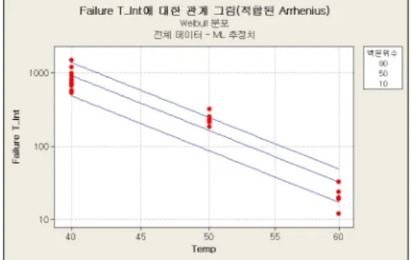
최우추정법(Maximum Likelihood Estimation)을 이
용해 고장시간에 적합한 분포를 탐색한 결과는 <Fig. 9>
Chi square statistics Degree of Freedom P-value
4.45 2 0.108
Table 10 Test for assumed common shape
Fig. 10 Relationship between Failure
and TemperaturePredictor Coefficient Standard Error Z 95%
Normal Lower Intercept -49.0947 3.51972 -13.95 -54.8841 Temp 1.51276 0.09735 15.54 1.3526 Shape
parameter 2.9396 - - -
Table 11 Estimation results of life and stress relationship
Test condition Acceleration factor
30 1.0
40 6.3667
45 15.3786
50 36.1457
55 82.7716
Table 12 Acceleration factor for each conditions 와 같다. 분석을 위한 소프트웨어로 Minitab 14.2를 사
용하였고 적합분포의 비교를 위해 수정된 A-D 통계 량(Adjust Anderson Darling statistics)을 비교하였다.
수정된 A-D(Adjust Anderson Darling) 통계량의 평 균을 비교한 결과 대수정규분포, 로그-로지스틱분포, 와이블분포, 로지스틱분포, 최소 극단 값 분포, 지수 분포 순으로 적합한 것으로 나타났다. 백재욱[1]에 따 르면 보통 A-D 적합도 검정 통계량의 값이 2 또는 3이 상이면 해당 분포는 적합하지 않는 것으로 보기 때문 에 최소 극단 값, 지수분포를 제외한다. 다른 분포들 의 수정된 A-D 통계량 값의 평균은 2 미만으로 적합 분포 후보군에 속한다. 서순근[13]에 따르면 수명 자 료의 85~95%가 와이블분포를 따르고 대수정규분포 가 와이블분포 다음으로 수명분포로 널리 쓰인다는 전문가의 경험적인 주장이 있다. 이런 점과 통계적 처 리의 장점을 고려하여 와이블분포를 적합분포로 선 택하였다.
시험 수준별 형상모수의 동일성에 대한 검정을 수 행한 결과는 <Table 10>과 같고, 동일형상모수 검정 결과 P-value가 0.05 이상이기 때문에 동일한 형상모 수를 신뢰수준 95%로 가정할 수 있다.
일반적으로 온도에 의한 가속수명시험에서 가장 널리 사용되는 수명-스트레스 관계는 아레니우스 모 형이고 아레니우스 관계는 다음 식 (1)과 같다.
(1)
단, L은 수명, T는 절대온도(섭씨온도+273℃), k는 볼쯔만 상수(8.617×10
-5eV/K), E는 활성화 에너지 (eV), A는 제품의 구조 및 시험방법에 따른 상수이 다. 식 (1)의 양변에 대수를 취하면
과 는 직 선관계가 성립하고 이는 식 (2)와 같다.
(2)
따라서
의 대수 값과 절대온도의 역수
를 그 래프에 도시했을 때 직선이 되면 아레니우스 모형을
따른다고 볼 수 있다[13]. 동일 형상모수로 추정한 결 과와 아레니우스 용지에 타점한 결과는 다음 <Fig.
10>, <Table 11>과 같다. 아레니우스 용지에 타점 결과 대수를 취한 고장시간과 온도 간에 근사적으로 선형 관계가 성립하기 때문에 아레니우스 관계가 적합하다 고 할 수 있다.
분석결과에 따라 구해진 활성화 에너지 1.51276을
바탕으로 보호된 환경에서 사용되는 정전위 전해식
가스센서의 정상 사용 온도를 30℃로 가정했을 때, 온
도별 가속계수를 도출하면 다음 <Table 12>와 같다.
Shape parameter() 2.9396 Allowed number of failures() 0
Specified period() 17,520 hours(2 years)
Test time() 1,000 hours
Confidence level 90%
Acceleration factor 36.1457(50℃)
Life level B5
Number of specimens() 7
Table 13 Qualification test design
3.7 보증시험 설계
도출한 가속계수로 목표로 하는 수명을 보증하기 위한 시험을 설계하였다. 정전위 전해식 가스센서는 일반적으로 최대 2년의 보증수명을 가정할 수 있다.
시험시간 및 시료 수는 보증시험 설계방법을 적용하 여 B
5수명 2년을 신뢰수준 95%로 보증할 수 있는지 설계하였다.
개의 아이템을 정해진 기간
까지 시 험하였을 때, 형상모수가
인 와이블 분포의
수명 이
이상임을 신뢰수준 100(1-
)%로 보증할 수 있는 샘플의 크기를 구하는 식은 식 (3)과 같다[14].
≥
× ×