THE CRASH BEHAVIOR ANALYSIS OF TRAIN VIRTUAL TESTING MODEL
Seungrok. Kim*
1, Jungseo. Goo
2, Taesoo. Kwon
3, and Kihwan. Kim
31Department of Virtual Engineering, Korea University of Science and Technology 52 Eoeun-dong, Yuseong-gu, Daejeon, 305-333, Korea
2Department of Rolling Stock System, Seoul National University of Technology 172 gongreung 2-dong, Nowon-gu, Seoul, 139-743, Korea
3Korea Railroad Research Institute
374-1 Woram-dong, Uiwang-si, Gyeonggi-do, 437-050, Korea [email protected]
Abstract
It is important to predict the collision behavior of a train consist to improve its crashworthiness.
To analyze crash behavior of train, four kinds of methods are mainly used so far. The first is method using multibody dynamics to predict the gross motion of the train set. The second uses 3D FE model to apply the section analysis method in order. The third is used to deduce design specification and evaluate the crashworhiness of a train by using 1D model. The last is to constitute 2D model to check overriding and coupling devices. The train evaluation procedures are so complex that it is difficult to understand or deal with. In this study, VTM for railway train was introduced to simplify the procedures. VTM involves 3D models, 1D models and dynamic components such as suspension and coupling. The method using hybrid concept model makes it possible to do all the things that are mentioned above. To analyze crash behavior tendency of VTM, the model was simulated and the simulation results were discussed.
INTRODUCTION
Train crashes are not frequent, but when they happen, they bring great disaster. I
n Europe, they have been investigating ways to minimize the damage resulting fr
om train crashes [1-8]. The proposed methods to improve train crashworthiness i
nclude the installation of an absorber on the front end of the lead car that absor
bs crash energy and the use of a specially designed coupler that reduces the occ
urrence of lateral buckling or overriding of cars during a crash [9]. Also, the pr
oposed model, VTM, to improve evaluation ability includes various dynamic com
ponents such as suspension and coupling devices. To evaluate crashworthiness of railway train, VTM introduction is necessary because train crash test on a real site takes lots of time and it is very expensive [9].
The collision simulation in three-dimension has many advantages. In the past, Be cause of the large amount of computation time it is so inefficient to simulate ful l rake train. But these days, the computer system is so improved that it is possi ble to consider simulation of the train set at any time. Three-dimensional simulat ion research has been initiated in some countries, although none has been formal ly announced yet [9]. In Korea, the National Support Research started investigati on on one-dimensional and three-dimensional crash safety simulation in the mid- 90s, the results of which have been applied to the development of the Korean H igh-Speed Train (KHST) [10].
In this paper, three-dimensional crash simulation technique using FE hybrid mode l instead of multibody dynamics are represented. The FEM (Finite Element Meth od), not like mutibody dynamics, does provide large deformation of individual str uctures and the gross motion can also be predicted. To realistically depict the nonlinear crash behavior of VTM, dynamic components such as suspension andco nnection devices, are considered and the simulation results are discussed.
MODELING The Constitution of Train VTM
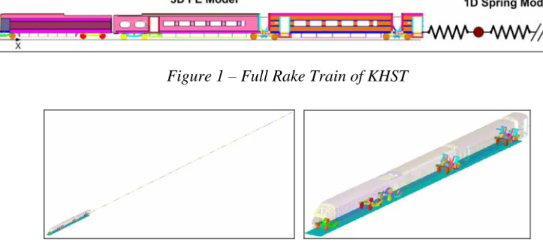
The VTM for KHST is composed of 20 vehicles in Figure 1. From the front, three
vehicles are modeled in three dimension and the others are created in one dimension in
Figure 2. The three cars are named as power car, motorized trailer car, and trailer carfrom the front. The power car is formed largely from Head structure, car body, and two
bogies. The two bogies include primary suspension, secondary suspension, and car
body-bogie connection components. The motorized trailer and trailer car also consist
largely of car body and bogies, and the bogies are composed of primary suspension,
secondary suspension, and car body-bogie connection components. In addition, Power
car and motorized trailer are connected and constrained by hook and side buffers. The
VTM consists of 38,440 solid elements, 1,890,125 shell elements, and 389 spring-
damper elements.
Figure 1 – Full Rake Train of KHST
Figure 2 – Full rake FE Model and first three cars of VTM
Dynamic Components
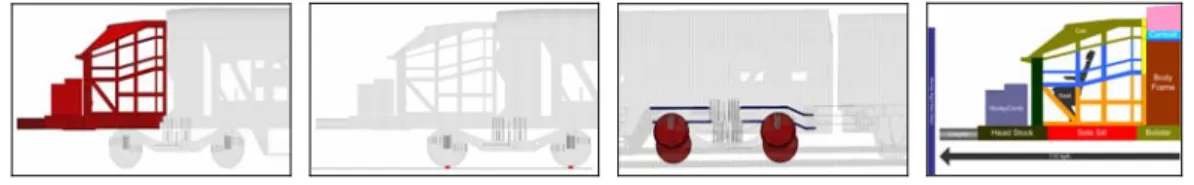
To represent realistic nonlinear behavior of KHST, Characteristics of dynamic components are investigated, they are created and tested. Power car is composed of two bogie, and each bogie consists of nine kind of dynamic components. The components are shown in the Figure 3. In Figure 4, suspension and connection components of Motorized trailer bogie and articulated bogie are also shown. The each 1D element was individually tested to make sure that it worked properly on load. Clearance and travel range were checked. Then, they were embedded in VTM after all the components were confirmed that they accurately followed defined curves.
Material and Property Definition
Material properties were defined by using eight types of material cards such as elastic, isotropic elastic plastic, piecewise linear plasticity, general nonlinear 6dof discrete beam, general nonlinear 1dof discrete beam, rigid, honeycomb, and simplified Johnson cook of LS_DYNA. Each of suspension components has characteristics of travel constraints.
The elastic, elastic plastic, and piecewise linear plasticity cards were selected for most
of the shell and solid elements, 1dof discrete beam for 1D vehicles, 6dof discrete beam
for suspension and connection components, honeycomb for honeycomb block, and
simplified Johnson cook for coupler. Also, section properties were defined by using
three kinds of section cards such as section beam, section shell, and section solid.
Figure 3 – Suspension and connection components of power car front and rear bogie, motorized trailer and articulated bogie
SIMULATION Contact Definition
There are four types of contacts. The first one is contact between rigidwall and the front area of power car, the second one is wheel-ground contact, the third one is contact between structures and the last one is self-contact. For those contact situations, three kinds of contact cards were defined: node to surface contact, surface to surface contact and singular contact. Node to surface contact card was used for wheel-ground contact, surface to surface contact card for contact between structures, and singular contact card for self-contact. Figure 4 shows rigidwall contact and self-contact, depicts wheel- ground, and represents contact between structures.
Figure 4 – Rigid wall , singular, wheel-ground, and wheel-car body contacts, and scenario
Collision Scenario
For the simulation of VTM, a scenario was adapted from SNCF accident scenarios. The accident scenario requires no intrusion into driver’s survival space, no overriding, and passenger’s deceleration at less than 5g in the collision with a 15-ton rigid obstacle at 110kph. Figure 4 shows the description of the scenario. The simulation was carried out by using LS-DYNA solver installed in IBM supercomputer system in KISTI.
CONCLUSION
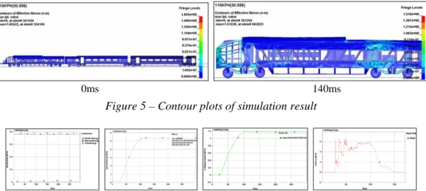
In this paper, anew introduced train VTM was simulated and its dynamic behaviors
were visually depicted in Figure 5. The simulation results showed that the scenario
requirement was satisfied, energy was conserved, and dynamic components followed properly defined curves.
The energy, crush length, and crush force were shown in Figure 6. The total energy of VTM is analytically 364.369MJ. The total energy, internal energy and kinetic energy of the train set are 384.789MJ, 6.48MJ and 378.029MJ from numerical results. Internal energy, crush length, crush mean force of head structure is 5.33[MJ], 1184.1[mm], and 4441.66[kN]. Although crush distance is little short, these results are reasonable from past studies [9, 10].
From the numerical result, it showed that the embedded dynamic component worked properly as compared to results of individual spring tests. The Figure 7 shows that a dynamic component, secondary coil spring composed of 10 spring elements, works properly according to force-displacement curve characteristic. The vertical spring rate of the spring is 0.6724±4.62 [kN/mm], deflection in clearance condition is 91[mm].
As stated early, the purpose of this paper is to provide dynamic behavior analysis of VTM and the simulation results visually showed the reasonable deformation behavior of front end structures, bogies, and dynamic components. Also, we could confirm most of results that we wanted to obtain without complex procedures through VTM.
In the future, to obtain more reliable VTM, unexpected behavior of VTM has to be investigated and wheel-rail contact considered.
0ms 140ms Figure 5 – Contour plots of simulation result
Figure 6 – Total, internal, kinetic energy, crush length, and crash force from simulation results
Figure 7 – Defined secondary coil spring rate curve and simulation result
ACKNOWLEDGEMENTS
This work was supported by the grant no. SR06008 from Korea Railway Research Institute funded by Ministry of Construction & Transportation.
REFERENCES
[1] Cleon, L.M., Legait J. and Leveque, D.: Passive Safety Concepts Applied to TER X7250 Diesel Railcar. In: Proceedings of WCCR’97, Vol. D, 1997, pp. 861-867.
[2] Cleon, L.M.: Tolerances a La Collision Des Materiels Ferroviaires Opimisation de La Securite Passive des Structures de Vehicule. In: Proceedings of WCCR’94, 1994, pp. 885- 891.
[3] Drazetic, P., Tassin, R. and Ravalard, Y.: Experimentation and Modeling of Climbing Phenomena of Guided Transport Vehicules. In: Proceedings of Institution of Mechanical Engineers (IMechE), Vol. 209, 1995, pp.11-17.
[4] Koo, J.S., Feng, Z.G., Domaszewski, M. and Renaudin, F.: Theoretical and Numerical Study of a Coupler for Crashworthy Design of TGV Power Car. In: Proceedings of Second International Conference on Integrated Design and Manufacturing in Mechanical Engineering, 1998, pp. 1-7.
[5] Kisielewicz, L.T. and Ando, K.: Crashworthy Rolling Stocks. In: Proceedings of PUCA’93, 1993. pp. 73-81.
[6] Lewis, J.H.: Developing o f Crashworthy Vehicles Structures for Railways. In: Proceedings of WCCR’94, 1994, pp. 893-900.
[7] Scholes, A.: Developing Crashworthiness Technology in Europe. In: Proceedings of WCCR’96, 1996.
[8] Smith, R.A.: Developing Crashworthiness Technology in Europe. In: Proceedings of Railway Gazette International, 1995, pp. 227-230.
[9] Han, H. S., Koo, J.S., 2003, "Simulation of Train Crashes," Vehicle System Dynamics, Vol.
40, No. 6, pp. 435~450.
[10] Koo, J.S., Kim, D.S., Cho, H.J., Kwon, T.S. and Choi, S.K.: Analysis on the Crashworthiness of the Full Rake Electric Multiple Unit Train. In: Proceedings of Korean Society for Railway, 2000, pp. 27-33.
[11] LIVERMORE SOFTWARE(2003), “LS-DYNA KEYWORD USER'S MANUAL”,
VERSION 970.
[12] KISTI(Korea Institute of Science and Technology Information) Supercomputing Center, 2005, "IBM System User's Reference, V. 1.9.5."