피로강도 향상을 위한 표면마찰교반법의 가공조건 및 비드형상
박정웅
*
․안규백**, †
․김흥주***
․조병철****
*
조선대학교 토목공학과
**
포스코 기술연구소 접합연구그룹
***
RIST 플랜트연구본부
****
조선대학교 대학원 토목공학과
Bead Shape and Conditions of Friction Stir Processing to Improve Fatigue Strength
Jeong-ung Park*, Gyu-baek An**
,
†, Heung-ju Kim*** and Byeong-cheol Jo*****Dept. of Civil Engineering, Chosun University, Gwangju 501-759, Korea
**Technical Research Laboratories, POSCO, Pohang 790-300, Korea
***Plant Research Center, Research Industrial Science and Technology, Pohang 709-600, Korea
****Dept. of Civil Engineering, Gradurate School of Chosun University, Gwangju 501-759, Korea
†Corresponding author : [email protected]
(Received July 23, 2013 ; Revised August 1, 2013 ; Accepted August 7, 2013)
A bstract
Burr grinding, Tungsten Inert Gas (TIG) dressing, ultrasonic impact treatment, and peening are used to improve fatigue life in steel structures. These methods improve the fatigue life of weld joints by hardening the weld toe, by improving the bead shape, and by creating the compressive residual stress. In this study, a new post-weld treatment method improving the weld bead shape and metal structure at the welding zone using Friction Stir Processing (FSP), a welding process, is proposed to enhance fatigue life. For that, a pin-shaped tool and processing condition employing Friction Stir Processing (FSP) is established through experiments. Experimental results revealed that fatigue life is improved by around 50% compared to as-welded fatigue specimens by reducing the stress concentration at the weld toe and by generating a metal structure finer than that of flux-cored arc welding (FCAW).
Key Words : Friction stir processing, Fatigue strength, Bead shape, Butt welding, Stress concentration, Microstructure
1. 서 론
강교량을 비롯한 기계 부품, 압력용기, 항공기, 선박, 해양 재킷 등의 구조물은 거의 용접이음으로 이루어져 있으며 이러한 구조물들은 기하학적 형상변화에 따라 높은 응력집중이 발생되고 이것이 피로 파괴의 한 원인 이 된다
1,2). 용접 연결부의 피로는 응력의 반복작용에 의해 발생하며 노치나 용접비드 등의 형상이 급변하여 응력집중부로부터 피로균열이 발생하여 피로강도가 극 단적으로 저하된다. 또한 언도컷, 용융불량
3)그리고 용
접부의 인장 잔류응력
4-6)등도 피로균열의 발생을 촉진 시켜 피로강도를 저하시키는 영향을 준다.
용접이음부의 토우부를 개선시켜 피로강도를 향상시 키는 방법이 기존 연구에서 많이 제안이 되고 있다. 용 접집중부의 피로강도를 향상시키는 대표적이면서 가장 용이하게 적용할 수 있는 방법으로는 그라인더 처리
7,8), TIG(Tungsten inert gas welding)처리
9-13), 햄머
피닝
14,15)등 다양한 표면처리 방법 등이 사용되고 있으
며, 이들 중 용접비드를 절삭하여 매끈하게 다듬는 작 업을 하거나 용접 토우부의 형상을 변화시킴에 따라 응 력집중을 감소시켜 피로강도를 향상시키는데 효과적인
연 구 논 문
1000
800
600
400
200
0
Elasto-plasticity
0.00 0.10 0.20 0.30 0.40 0.50 0.60 0.70
Stain
Stre ss( N/m m
2)
(b) Stress-strain curve
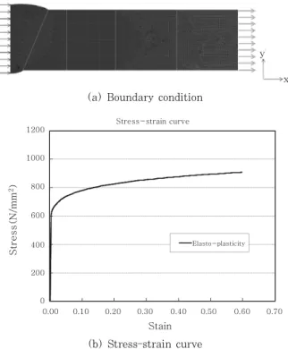
Fig. 1 Boundary condition and stress-strain curve
Table 1 Stress concentration factor(Kt) according to mesh size
Mesh size
(mm) 0.1 0.2 0.3 0.4 0.5
Kt 1.75 1.64 1.56 1.48 1.42
로강도를 향상시키는 새로운 피로강도향상법을 실험에 의해 검증하였다. 이를 위해 먼저 유한요소법을 이용하 여 용접비드의 응력집중계수를 최소화 할 수 있는 최적 의 비드형상을 도출하였다. 이러한 비드형상에 알맞은 FSP tool의 형상과 적절한 금속 미세조직을 얻기 위한 tool의 이동속도, tool회전속도, tilted angle을 다양하 게 변화시켜 적절한 FSP 가공조건을 설정하였다. 이렇 게 결정된 가공조건으로부터 FSW 처리된 피로시험편 과 as-weld 시험편에 대해 피로실험을 실시하였다.
2. 피로강도향상을 위한 비드형상 파라메타 연구
2.1 유한요소 크기의 영향
유한요소해석에 사용되는 요소의 크기가 응력집중계 수에 미치는 영향을 검토하기 위해 비선형해석 전문 프 로그램인 MSC.Marc를 사용하였다. 사용된 요소는 4 절점 2차원 평면응력요소를 사용하였다. Fig. 1(a)에 서 요소의 형상과 경계 조건을 보여주고 있다. 모델의 두께는 25mm이고, 용접금속을 중심으로 대칭성을 고 려하여 모델의 왼쪽을 대칭조건으로 고정하고 타단을 균일하게 인장응력이 280MPa이 되도록 하였다. 탄소 성해석에 사용한 재료의 기계적 물성치는 Fig. 1(b)와 같이 응력-변형률관계를 가지고 있으며, 이때 탄성계수 E=205.3(GPA), 포와송비는 0.3 이다. 식(1)은 응력 집중계수(Kt)를 계산하는 식을 보여주고 있으며, 이것 은 용접 집중부에 작용하는 최대의 응력과 공칭응력과 의 비율이다.
유한요소 크기에 따른 응력의 차이를 Table 1에 보 여주고 있는 것과 같이 유한요소 크기가 커짐에 따라 응력집중계수(Kt)는 거의 선형적으로 작아지는 것을 알 수 있다. 따라서 본 해석에서는 유한요소 의 크기 (가로/세로)를 0.1mm/2mm 로 일정하게 설정하여 모 든 해석에서 요소의 크기의 영향을 받지 않도록 수행하 였다.
m ax
(1)
여기서,
m ax = 노치부의 최대응력
= 응력집중이 없는 것으로 계산한 공칭응력
2.2 토우부 곡률반경의 영향
용접토우부의 형상은 피로강도에 매우 큰 영향을 미
친다. 따라서 FSP에 의한 비드형상 가공시 적절한 형
상을 도출하기 위해 곡률반경을 변화시켜 해석을 실시
하였다. Fig. 2는 곡률반경과 그 곡률이 토우부로부터
모재에 접촉하는 거리를 보여주고 있다. 이러한 조건을
Table 2와 같이 각각 곡률반경, 접촉위치 그리고 응력
집중계수를 보여주고 있다. 결과에 의하면 곡률반경이
1mm를 기준으로 0.5mm 일 때 응력집중계수는 11%가
증가하였으나, 곡률반경을 2.4mm, 4.81mm, 7.21mm
로 증가시키면 응력집중계수는 13%, 26%, 32% 로
Fig. 2 Radius of curvature and contact distance
Table 2 Stress concentration factors vs. radius of curvature
ρ (mm)
Contact Distance (mm)
θ (degree)
h (mm)
l (mm)
t
(mm) Kt %
0.5 1 135 10 29.94 25 2.36 11
1 2 135 10 29.94 25 2.1 0
2.4 3 135 10 29.94 25 1.81 13
4.81 4 135 10 29.94 25 1.56 26
7.21 5 135 10 29.94 25 1.44 32
(a) As-welded
(b) FSP
Fig. 3 Stress distribution of as-weld and FSP model
Table 3 Kt of as-welded 와 FSW
Top(Kt) Bottom(Kt)
As-weld 2.05 1.99
FSP 1.17 1.48
Type A B C D
Shape
Shoulder
size ø12 ø10 ø6 ø6
Pin size
(Top) ø4 ø5 ø3 X
Pin size
(Bottom) ø3 ø4 ø2 X
Pin
depth 2mm 2mm 1.5mm X
Table 4 Shape and dimension of tool 감소한 것을 볼 수 있다. 따라서 본 연구에서는 FSP장
치를 고려하여 응력집중계수가 감소하도록 곡률반경을 4~5mm가 되도록 설정하였다.
2.3 As-weld 와 FSP 용접시험체의 응력집중 계수
본 실험에 들어가기 전 맞대기용접부에 대해 as- weld 용접 시험체와 용접토우부 마찰교반개질한 시험 체에 대해 응력집중계수를 비교검토를 위해 유한요소해 석을 실시하였다. 해석에 사용한 요소의 크기(가로/세 로)는 0.1mm/2mm 이고, 곡률반경은 4~5mm가 되 도록 모델링하였다. Fig. 3은 as-weld 시험체와 용접 토우부 마찰교반개질한 시험체의 상부의 응력분포를 보 여주고 있다. 모든 모델에서 응력집중은 용접비드 토우 부에서 발생하였고, 응력집중계수는 As-weld 시험체인 경우 1.99~2.05 이고, 마찰교반된 시험체에서는 1.17~
1.48 로 나타났다. 따라서 용접토우부를 곡률반경 4~
5mm 처리함으로서 응력집중이 감소하는 것을 알 수 있다. 또한 개선 후 응력집중계수값은 root부에서 더 크게 나타났다. 이러한 결과로부터 FSP처리된 용접토 우부에서 응력집중이 감소하여 피로강도가 향상될 것으 로 예상된다.
3. FSP에 의한 가공조건 3.1 tool형상과 가공속도
적절한 FSP 가공조건을 결정하기 위해 평판위에 Table
4와 같은 4가지의 tool형상, too 회전속도 500, 1,000rpm,
Fig. 4 Micro section
BM FSW FCAW
Ferrite 계
Pearlite 계
Fig. 5 Grain size of BM, FSW, FCAW
Fig. 6 Fatigue testing machine
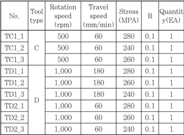
Table 5 Conditions of fatigue test No. Tool
type
Rotation speed (rpm)
Travel speed (mm/min)
Stress
(MPA) R Quantit y(EA) TC1_1
C
500 60 280 0.1 1
TC1_2 500 60 240 0.1 1
TC1_3 500 60 260 0.1 1
TD1_1
D
1,000 180 280 0.1 1
TD1_2 1,000 180 260 0.1 1
TD1_3 1,000 180 240 0.1 1
TD2_1 1,000 60 280 0.1 1
TD2_2 1,000 60 260 0.1 1
TD2_3 1,000 60 240 0.1 1
Fig. 4는 용접 개질부의 마크로 단면이고 단면에서는 모재(BM), 개질부(FSP) 그리고 용접부(FCAW)를 보여 주고 있다. Fig. 5는 대표적으로 이동속도가 60mm/min 이고, 회전속도는 500 rpm의 모재, FSP, FCAW부의 grain size 을 보여주고 있다. 각 부분에 대해 5개소의 대표부분을 측정 후 평균값은 Base metal 부에서는 ferrite 계가 19.03μ㎡ 이고, Pearlite 계가 6.32μ㎡
였고, FSP부분에서는 ferrite 계가 6.83μ㎡ 이고, Pearlite 계가 1.54μ㎡ 였고, FCAW 부분에서는 사이 즈는 ferrite 계가 12.28μ㎡ 이고, Pearlite 계가 5.21μ㎡ 이다. 모재의 조직에 비하여 FSP에 의해 개 질된 부분의 조직이 미세하며, 조직의 미세화에 따라서 인성 및 강도가 향상 될 것으로 판단된다. 피로성능에 영향을 주는 요인은 여러 가지가 있으나, 형상의 영향 즉 응력집중의 영향을 많이 받게 되며, 본 연구에서는 FSP에 의한 형상 및 조직을 개선하여 피로성능을 향상 하고자 하였다. 조직의 미세화 등 조직만의 영향에 의 해서 피로성능의 형상 정도를 파악하기는 본 연구의 범
4.1 피로실험 조건
본 피로실험에 사용된 시험기는 Fig. 6과 같이 축 인
장/압축에 대해 최대용량 ±50ton이고 유압서브에 의해
구동된다. 실험은 하중제어방식에 따라 4∼6Hz로 하였
고, 하중부하조건은 편진 인장진폭이고 R=0.1로 실시
하였다. 시험조건은 Table 5와 같이 두 가지 tool type
(C, D), 회전속도 그리고 이동속도를 달리하여 3가지
가공조건에 대해 총 9개이고 하중조건은 3영역(240,
260, 280MPa)에서 실시하였다.
Specimen : 2-1-1
Fig. 7 Shape of specimens
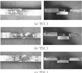
(a) TC1_1
(b) TD1_1
(c) TD2_1
Fig. 8 Fractured specimens
TC 1_1,2,3 TD 1_1,2,3 TD 2_1,2,3 400
350
300
250
200
150
100
1,000 10,000 100,000 1,000,000 10,000,000
Number of cycle to failure (N)
St ress ran ge ( M Pa )
As-welded
FSP
Fig. 9 Fatigue testing results
σ
x(y)
(a) As-weld
σ
x(y)
(b) FSP
Fig. 10 Schematic Stress distribution in toe 시험체의 형상은 Fig. 7과 같이 두께는 25mm이고,
전체 폭은 100mm이며 전체길이는 약 430mm이다.
시험체의 중앙 평행부는 폭 50mm 이고, 평행부의 길 이는 100mm가 되도록 제작하였다. 시험체의 중앙에는 맞대기용접되어 있고, 피로강도 향상시키기 위해 토우 부에 FSP 처리 하였다. 피로시험편의 제작 및 실험은 ASTM
21)과 JSME
22)규격에 따라 실시하였다.
4.2 피로실험결과 및 응력집중계수
피로시험편의 파단모습을 Fig. 8에서 보여주고 있다.
피로균열의 시작은 응력이 집중되는 이면 또는 전면 토 우부를 기점으로 균열이 발생, 진전되어 파괴에 도달 되었다. Fig. 9는 맞대기 피로시험체의 S-N선도를 보 여주고 있으며, 이때 as-welded 실험결과는 직선이며 심볼 ●, ■, □ 는 각각의 가공조건에 의해서 개선된 시험편의 피로시험 결과를 나타낸 것이다. 통상 S-N 선도는 14∼16개의 시험결과로 그래프를 그리지만, 본 연구에서는 FSP 기술의 피로 성능과 가공조건에 대한
가능성을 평가하는데 초점을 맞추었다. TC1의 가공조 건이 TD1과 TD2의 가공조건에 비해 피로강도가 향상 되는 것을 알 수 있다. 피로수명의 향상 정도는 본 연 구에서 적용한 강재의 설계하중(250MPa)을 기준으로 할 때 약 50%정도가 향상됨을 알 수 있었다. 따라서 본 연구에서 제안하고 있는 마찰교반에 의한 피로강도 향상법은 용접부 피로수명을 향상시키는데 효과적인 것 으로 판단된다. 이러한 현상은 FSP에 의해 토우부의 금속의 개선과 Fig. 10에서와 같이 기존의 용접이음부 에 비하여 FSP에 의해서 용접비드 toe부의 형상을 개 선하여 응력집중을 제어한 시험편의 피로성능이 향상됨 을 알 수 있었다.
피로실험을 실시한 시험체를 대상으로 파단위치에 대
한 응력집중계수를 계산하기 위해 피로실험 전 치과용
고무인상재를 이용해서 비드형상을 본떠 총 9개의 시험
편 중 6개의 피로시험편에 대해 유한요소해석을 하였
다. Fig. 11은 TC1_1의 비드형상을 기준으로 3차원
탄소성해석을 실시하여 도출된 응력분포를 보여주고 있
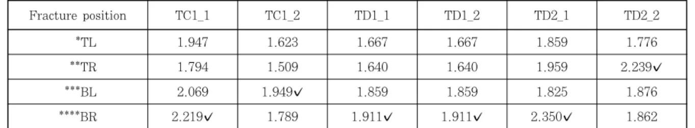
다. Table 6은 해석결과로부터 표면개질된 시험체의
응력집중계수를 보여주고 있으며, Fig. 12는 Table 6
Fig. 11 Stress distribution of TC1_1
TL TR
BL BR
L R
Fig. 12 Fracture position of specimen
✔: fracture position in experiment
에서 보여주고 있는 파단위치를 나타내고 있다. 또한 심볼 ✔는 피로실험에서 피로균열의 시작위치를 표시하 고 있다. 응력집중계수는 상면보다 하면의 토우부가 더 큰 값을 보여주고 있어 피로균열의 시작위치를 암시하 고 있으며, 총 9개의 시험체에서도 2개의 시험편을 제 외하고는 모두 이면 비드로부터 피로균열이 시작되어 HAZ부를 진전하다가 결국 파괴되어 유한요소해석에 의한 응력집중계수와 일관성 있는 결과를 보여주고 있다.
5. 결 론
본 연구에서는 맞대기 용접부의 피로강도를 향상시키 는 새로운 피로강도향상법에 대해 피로실험을 실시하였 다. 또한 그 피로시험편에 대한 응력집중계수 값을 구 하여 다음과 같은 결론을 도출하였다.
1)기존의 피로강도향상법을 보완한 새로운 피로강도 향상법인 FSP방법에 대해 피로강도를 평가 하였다.
2)FSW을 응용한 피로강도향상을 위한 최적의 마찰
교반용접기의 tool형상과 이동속도, tool회전속도를 변 화시켜 가공조건 및 tool형상을 도출하였다.
3)맞대기용접부에 대해 FSP를 적용한 피로실험결과 에 의하면 설계하중(250MPa)을 기준으로 할 때 as- welded 시험편에 비하여 피로수명이 약 50% 정도 향 상 되었다.
4)피로균열의 시작은 모두 토우부에서 시작하였고 그 중 66%가 이면 토우부에서 시작하여 파괴되었다. 시험 체의 비드형상을 기준으로 유한요소해석에 구한 응력집 중계수도 피로실험결과와 잘 일치하였다. FSP시험편과 같이 토우부가 완만한 곡률을 가지고 있는 경우 유한요 소해석과 같은 구조물의 전체형상으로부터 응력집중계 수를 계산되어야 한다.
후 기
이 논문은 2012년도 정부(교육과학기술부)의 재원으 로 한국연구재단의 지원을 받아 수행된 기초연구사업임 (2012-0008837)
References