http://dx.doi.org/10.5302/J.ICROS.2013.12.1856 ISSN:1976-5622 eISSN:2233-4335
STATCOM
을 사용한 다기 전력 계통의 버스 전압 조절을 위한모델 기반 PID 제어기 설계
Innovative Model-Based PID Control Design for Bus Voltage Regulation with STATCOM in Multi-Machine Power Systems
김 석 균, 이 영 일*, 송 화 창, 김 정 수
(Seok-Kyoon Kim
1, Young Il Lee
2, Hwachang Song
2, and Jung-Su Kim
2)
1
Korea University
2
Seoul National University of Science and Technology
Abstract: The complexity and severe nonlinearity of multi-machine power systems make it difficult to design a control input for voltage regulation using modern control theory. This paper presents a model-based PID control scheme for the regulation of the bus voltage to a desired value. To this end, a fourth-order linear system is constructed using input and output data obtained using the TSAT (Transient Security Assessment Tool); the input is assumed to be applied to the grid through the STATCOM (STATic synchronous COMpensator) and the output from the grid is a bus voltage. On the basis of the model, it is identified as to which open-loop poles of the system make the response to a step input oscillatory. To reduce this oscillatory response effectively, a model-based PID control is designed in such a way that the oscillatory poles are no longer problematic in the closed loop. Simulation results show that the proposed PID control dampens the response effectively.
Keywords: power system, bus voltage regulation, model estimation, optimization, PID control, TSAT
Copyright© ICROS 2013
I. INTRODUCTION
In modern day practical systems, electromechanical oscillations have been observed [1-5]. Local oscillations might appear during disturbances when a fast exciter is used on the corresponding generator to stabilize a power system, and the oscillation can persist if the system has insufficient damping. With weak transmission interfaces, increasing loads in the power system can cause inter-area oscillations. Moreover, these result in oscillation modes for several generators with low damping in power systems [5].
Since these oscillations may bring about total or partial power interruption under severe system conditions, it is crucial to reduce them properly [3]. This paper focuses on control measures for diminishing bus voltage oscillations in multi-machine power systems.
Reactive power sources are commonly utilized for bus voltage regulation in the presence of disturbances [6]. A STATCOM (STATic synchronous COMpensator) is a representative reactive power compensation device, and it is composed of three-phase pulse width modulated voltage
* 책임저자(Corresponding Author)
논문접수: 2012. 12. 26., 수정: 2013. 2. 18., 채택확정: 2013. 2. 21.
김석균: 고려대학교 전기공학과([email protected]) 이영일, 송화창, 김정수: 서울과학기술대학교 전기정보학과 ([email protected]/[email protected]/[email protected])
※ This study was supported by Seoul National University of Science and Technology.
source converters; further, it is popularly employed owing to its high control bandwidth for the purpose of regulating the bus voltage by controlling fast responding reactive power outputs [6]. Therefore, the parameters of the STATCOM are considered as the main control means for voltage regulation during disturbances. In the literature, there are a few results from attempts to reduce oscillations in power systems using STATCOM as the control input [7-9]. These papers proposed PID control schemes to reduce the oscillation [7,9]. However, the exact structure and the parameters for the power system model are required to determine the PID gains, and closed-loop stability is not considered. A robust control scheme has also been developed to deal with model uncertainties [8]; however, this controller depends highly on the power system model structure.
This paper proposes an estimated model-based PID
control scheme for reducing oscillatory behavior in the bus
voltage response of a multi-machine power system. Unlike
[7-9], the proposed control scheme does not require an
exact model and its parameters. In particular, first, a LTI
(Linear Time Invariant) model is built using step responses
of the power systems, which represents the input-output
relationship of the real system. To construct the above
mentioned model, the input for the step response is the
reactive current injected by the installed STATCOM and the
1
1 5
6
2
2
7 8 9
10
4
4
11 3
3
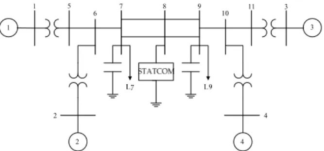
그림 1. 4개의 발전기와 11개의 버스로 구성된 전력 계통.
Fig. 1. 11-bus 4-machine power system.
0 1 2 3 4 5 6 7 8 9 10
0 0.1 0.2 0.3 0.4
Time (s)
Pu
Test Input at STATCOM
0 1 2 3 4 5 6 7 8 9 10
0.98 0.985 0.99 0.995 1
Pu
Voltage Response at Bus 8
Time (s)
그림 2. 8번 버스 전압의 계단 응답.
Fig. 2. Bus voltage step response at bus 8.
output is the corresponding bus voltage. In this study, building the LTI model is reformulated as a nonlinear optimization problem that is solved using a hybrid GA (Genetic Algorithm) [10,11]. In view of the constructed model, one can observe that there are two open-loop poles close to the imaginary axis and that these cause the oscillatory behavior of bus voltage response. On the basis of the observations of the model, a model-based PID control scheme is designed in such a way that the PID gains are determined in order to reduce the oscillatory behavior by moving the problematic poles to desirable places [13,14]. However, it is impossible to arbitrarily assign the closed-loop poles owing to the lack of degrees of freedom; i.e., the order of the closed loop system is higher than the number of PID controller gains. To overcome this difficulty, a set of PID gains is chosen by solving an optimization problem, so that the closed-loop poles are placed as close as possible to the desired ones that are determined by taking the desired time-domain specification into account. Simulation results using a two area test system show that the oscillatory behavior is effectively dampened using a PID controller with the gains provided by the proposed scheme.
II. SYSTEM DESCRIPTION AND IDENTIFICATION This section describes the multi-machine power system equipped with a STATCOM under consideration in this paper and briefly explains the identification procedure.
1. Multi-Machine power system with STATCOM
In general, power systems are subject to abrupt changes due to lightning, storms, equipment failures, and so on.
Under these circumstances, the electric power supply from the generators must be stable. Recently, the STATCOM has been popularly utilized for this purpose. This paper considers the 11-bus 4-machine power system depicted in Fig. 1 [1].
In this figure, the circles with numbers from 1 to 4 represent the generators. The thick lines with numbers indicate the buses providing the power. The STATCOM in the figure consists of three-phase VSCs (Voltage Source
Converters) and is a shunt FACTS device. Moreover, it is used for regulating and dampening the bus voltage by controlling the reactive power [12]. Among these 11 buses, this paper assumes the bus voltage magnitude at bus 8 as the output and the output of the STATCOM as the control input for the system. For the purpose of investigating the power systems dynamics using these input and output data, step response is considered, which is obtained using the TSAT. Fig. 2 illustrates the step response.
In view of the step response shown in Fig. 2, it is reasonable to suppose that the system is an sum of two second-order systems; one second-order system contributes to the initial fast jump-like behavior and the other causes the slow oscillatory behavior. On the basis of this observation, it is assumed that the structure of the system to be identified is of the form:
, (1)
where
and
are the Laplace transforms of the input (STATCOM) and the output (Bus voltage at bus 8), respectively. Moreover, regarding pole locations, the step response suggests that the open-loop poles of system (1) might be given as depicted in Fig. 3.
그림 3. 극점의 예상 위치.
Fig. 3. Expected pole locations.
In other words, there are two open-loop poles close to the imaginary axis that make the step response persistently oscillatory. In addition, there are two other poles that are away from the imaginary axis. Therefore, it is obvious that the two poles close to the imaginary axis are problematic, and it is reasonable to set the control objective to move the dominant oscillatory poles away from the imaginary axis by designing a feedback control to be implemented via the STATCOM. On the basis of the system structure in equation (1), the system is identified in the following section.
2. System identification
In order to identify system (1), its state-space realization is assumed to be of the form
(2)
where
,
,
, and
.
The system identification problem is to determine the system parameter that makes the input and output responses of the model (2) as close as possible to the real input and output data obtained from the TSAT. This system identification problem can be formulated as the following optimization problem:
min
subject to (1) and (2), (3) where
, (4)
and
is the bus voltage data shown in Fig. 2.
It is easily seen that this optimization problem tries to find the optimum parameters for the smallest error between the output of model (2) and the real output. The optimization problem can be solved using any optimization solver, e.g., a genetic algorithm [10,11] or particle swarm.
A genetic algorithm is employed in this study and the system identification result (i.e., the optimal ) from solving the optimization problem (3) is presented in Section III. In the following section, a model-based PID control scheme is designed such that the control objective is met using the estimated model.
III. MODEL-BASED PID CONTROLLER DESIGN In this section, on the basis of the estimated LTI model, a model-based PID control scheme is adopted to regulate and dampen the bus voltage, which is assumed to take the following form:
,
, (5)
,
where
is the reference for the model output
. Hence, the closed-loop system consisting of the estimated LTI model and the PID controller (5) can be written as
, (6) where
,
,
and
. (7)
The corresponding equilibrium point is obtained by solving
, (8) where
denotes the equilibrium points of . Now, the error variable is defined as
. Hence, the error dynamics is given by
(9)
It can be easily verified that, for an arbitrary
(constant reference),
converges to
if the closed-loop system (9) is asymptotically stable. A straightforward method to achieve this is to determine gains
,
, and
in such a way that the poles of the error dynamics (9) are assigned to a desired position, which is selected in consideration of the time-domain performance specification.
However, the closed-loop poles cannot be arbitrarily
assigned using the PID gains owing to the lack of degrees
of freedom. Note that the order of the closed-loop system
is higher than the number of the controller parameters.
1
2d d
j
w-
z1 2
d d
jw
z- -
1 d
a w
d d
z w
2 d 3 d a w a w
그림 4. 원하는 폐루프 시스템의 극점 위치.
Fig. 4. Desired closed-loop poles.
0 1 2 3 4 5 6 7 8 9 10
0.985 0.99 0.995
Time (s)
Pu
Bus Voltage Response of the Estimated LTI System
-12 -10 -8 -6 -4 -2 0
-20 -10 0 10 20
Eigenvalues of the Estimated LTI System
( )
ypt
m
( )
y t
Re
Im
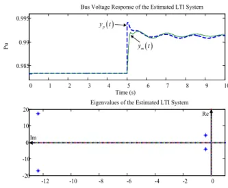
그림 5. 추정한 LTI 시스템의 출력 궤적과 극점 위치.
Fig. 5. Output trajectory and open-loop poles of the estimated LTI system.
Therefore, the best we can expect is that the closed-loop poles are placed as close as possible to the desired pole location by adjusting the PID gains.
The desired closed-loop pole location is chosen as shown in Fig. 4. Note that
and
in Fig. 4 denote the desired damping and oscillation coefficients for the closed-loop system. Since the persistent oscillation in the step response is caused by the two poles close to the imaginary axis, if those two poles are moved in the closed loop such that the time-domain specification is satisfied and the other poles are placed properly, the control objective is achieved. This is why such a choice for the closed-loop pole location is made.
Hence, for appropriate
and
,
,
,
,
,
, and
must be found such that
±
,
,
,
, where
, ⋯, are the eigenvalues of matrix
. As explained earlier, since it is not always possible to find an exact solution, the problem of finding the PID gains and parameters
,
, and
are formulated as an optimization problem with the selected
and
.
min
∥
∥
(10) subject to
1. ℛ
, ⋯, (11)
2.
, (12)
By minimizing the cost function (10), it is expected that the closed-loop poles resulting from the proposed PID control scheme are as close as possible to the desired ones.
Besides, constraint (11) implies that the closed-loop system is asymptotically stable and constraint (12) results in the non-dominant three closed-loop poles to be placed to the left of the dominant ones.
In the following section, the simulation results are described.
IV. SIMULATION RESULTS
This section presents the system identification result based on the optimization problem (3) and shows the performance of the proposed PID controller (5) with the gains obtained from (10). To solve the optimization problem (3), this study employs a hybrid genetic algorithm [10,11]. The optimal parameters are given by
,
,
,
,
,
,
,
where
⋯
represents the optimal parameters. The upper panel in Fig. 5 shows the step responses obtained from the TSAT and the estimated model (2) with the optimal parameters, and the lower panel shows the poles of the estimated model.
The upper panel in Fig. 5 shows that the estimated model approximates the input-output behavior of the power system with acceptable accuracy. Besides, as determined earlier from the step response, when looking at the poles of the estimated model, it turns out that there are indeed two problematic open-loop poles close to the imaginary axis.
Let
, , be the open-loop poles. These values are given by
± and
± .
0 0.5 1 1.5 2 2.5 3 3.5 4 0.9
0.95 1 1.05
Time (s)
Pu
Bus #8 Voltage Response
Uncontrolled Voltage Response
Controlled Voltage Response
그림 6. 개루프 시스템과 폐루프 시스템의 8번 버스 전압 응답.
Fig. 6. Bus #8 voltage response of the uncontrolled and controlled systems.
Moreover, let
and
be the damping and oscillation coefficients, respectively, for the oscillatory open-loop poles, which are given as
and
. Using this information with the open-loop poles in mind, choose
and
(13) The optimal PID gain and parameters
,
,
are then obtained by solving (10) using SQP (Sequential Quadratic Programming) as follows:
,
,
,
,
,
. (14) These optimal values lead to the following closed-loop poles:
± , , , .
Furthermore, the resultant damping and oscillation coefficients for the dominant closed-loop poles are given by
and
,
which are very close to the desired values (13). With these gains, the PID controller is implemented with a slight modification to the differential term:
, (15)
where
.
Using these, a simulation is run for the following scenario in the TSAT.
1. The system is in a pre-fault state.
2. At s, a transmission line fault occurs.
3. At s, the fault is removed by opening the breakers of the faulted line.
Fig. 6 shows the simulation result. In this figure, the dotted line and the solid line indicate the uncontrolled and controlled bus voltage responses, respectively.
0 0.5 1 1.5 2 2.5 3 3.5 4
0.9 0.95 1 1.05
Time(s)
Pu
Bus #7 Voltage Response Uncontrolled Voltage Response
Controlled Voltage Response
0 0.5 1 1.5 2 2.5 3 3.5 4
0.9 0.95 1 1.05
Pu
Bus #9 Voltage Response
Uncontrolled Voltage Response
Controlled Voltage Response
Time(s)
그림 7. 개루프 시스템과 폐루프 시스템의 7번과 9번 버스 전압 응답.
Fig. 7. Bus #7 and #9 voltage responses of the uncontrolled and controlled systems.
0 5 10 15 20 25 30 35 40 45 50
0.8 0.9 1
Time (s)
Pu
Generator #1 Active Power
0 5 10 15 20 25 30 35 40 45 50
0.95 1 1.05
Pu
Generator #2 Active Power
0 5 10 15 20 25 30 35 40 45 50
1.1 1.2 1.3
Pu
Generator #3 Active Power
0 5 10 15 20 25 30 35 40 45 50
0.9 1 1.1
Pu
Generator #4 Active Power Uncontrolled Active Power
Controlled Active Power
Uncontrolled Active Power Controlled Active Power
Controlled Active Power
Uncontrolled Active Power
Controlled Active Power
Uncontrolled Active Power Time (s)
Time (s)
Time (s)