서론 I.
(RLG: Ring Laser Gyroscope)
(LINS: Laser Inertial Navigation System)
[1,6,8-10]. ,
, , ,
, ,
, ,
.
[7].
95%
/ [7,11-13].
, .
.
95%
1
* (Corresponding Author)
: 2011. 8. 20., : 2011. 9. 5., : 2011. 9. 25.
, , :
([email protected]/[email protected]/[email protected]) : ([email protected])
.
1 /
.
.
/
.
SFD (Start-up Fault Detection)
CFD (Continuous Fault Detection)
PFD (Performance Fault Detection) ,
2
3 .
2 3 16bit (BMONW1,
BMONW2, BMONW3) ,
2 1
(INU_CW1) .
. II
,
Fault Detection Method of Laser Inertial Navigation System Based on the Overlapping Model
, , , *
(Cheon-Joong Kim
1, Ki-Jeong Yoo
1, Hyeon-Suk Kim
1, and Joon Lyou
2)
1Agency for Defense Development
2Chungnam National University
Abstract: LINS (Laser Inertial Navigation System) consists of RLG (Ring Laser Gyroscopes)/accelerometers and provides real-time navigation information to the target system. Therefore it is very important to make a decision in the real time whether LINS is in the normal operation or not. That is called a fault detection method. In this paper, we propose the fault detection method of LINS based on the overlapping model. We also show that the fault detection probability is increased through overlapping the hardware model and the software model. It is verified through the long-term operation and RAM (Reliability Availability Maintainability) analysis of LINS that the fault detection method proposed in this paper is able to detect about 97%
of probable system failures.
Keywords: INS, fault detection, RLG, overlapping model
Copyright© ICROS 2011
III
IV .
레이저 관성항법장치 시스템 구성 개요 II.
RLG .
1 ,
1 .
동작원리 및 구성품 1. RLG
. RLG
, (dither),
, 2 , 2
,
(piezo actuator), , ,
RAVS (Relative Angular Velocity Sensor) [1-5].
실리콘 가속도계 동작원리 및 구성품 2.
.
, ,
, .
[8].
레이저 관성항법장치 전자모듈 3.
센서제어기 보드 3.1
3
, RLG .
, , PLC
(Path Length Control) / , .
보드 3.2 MUX 3
.
저 고전압 공급 보드 3.3 /
(+5,±15) RLG (±100,-180,-1000,+3200)
.
자이로 인터페이스 보드 3.4
, . 가속도계 인터페이스 보드
3.5
. 항법컴퓨터 보드
3.6
.
1. .
Fig. 1. Schematic of LINS.
2. .
Fig. 2. Processing method of fault detection signal.
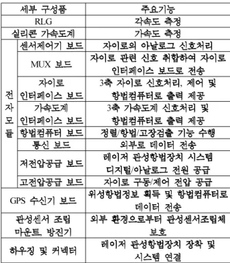
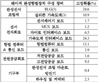
1. .
Table 1. Functional description of LINS components.
RLG
MUX
3 ,
3 / /
/ / GPS
,
레이저 관성항법장치 고장검출 기법 III.
하드웨어 고장검출 기법 개발 1.
3 .
,
. 2~4
.
레이저 관성항법장치 하드웨어 고장검출 기능 1.1
자이로 출력펄스 고장검출 1.1.1
II RLG
Sin Pulse Cos Pulse .
3. (SIN, COS).
Fig. 3. Interferometeric signals of detector.
SIN COS
3 .
3 VF (Voltage to Frequency) MUX
.
2MHz . 3
2arcsec , 2 .
70 130deg/s ,
(360Hz~440Hz)
. 1/(
) 20 ,
4
. 1/(
) 4
, (100deg/s )
4
. 몸체진동기 동작 고장검출 1.1.2
,
. RLG
, .
360~440Hz
1/310 1
zero-rate .
자이로 방전 고장검출 1.1.3
RLG /
. +3200V
, -1000V
.
, -1000V
.
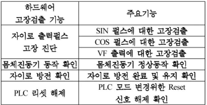
2. .
Table 2. Functional description of hardware fault detection.
SIN COS VF
PLC PLC Reset
3. .
Table 3. Hardware fault detection signals.
(LI, DI, PLC)
3 3
BUS Local BUS
3
4. .
Table 4. Hardware self-fault detection function.
Reset
BUS Local Hold
고장검출 1.1.4 PLC Reset
PLC Reset PLC
, PLC Offset
Reset . PLC Reset PLC Reset .
고장검출을 위해 출력되는 하드웨어 신호 1.1.5
AD (Analog to Digital)
. LI (Laser
Intensity), DI (Current Difference), VPLC, VDIS, VDTH . LI
DI
( 300uA) VPLC
, 6 7
.
AD .
가 고장검출
( ) LI
LI ,
2.0V - 5.0V . 3.0 - 4.5V ,
( 300uA) .
- LI 1.5V
2 ,
.
2.0V .
나 고장검출
( ) DI
RLG Cathode
Anode 5K
100 AD . DI
(
300uA) 4uA .
다 전압 고장검출
( ) PLC
PLC PLC
. 5 Volt
0 Volt .
.
PLC . PLC
PLC
PLC .
라 전압 고장검출
( ) VPLC
PLC power amp
(60 ) -180V
1M 12K 12K
AD . ±2.5V PLC
VPLC -150V(-2.5V) .
마 방전 전압 고장검출
( ) VDIS( )
RLG 1/350 AD
. Nominal -980V ±180V
. AD
.
바 몸체진동기 전압 고장검출
( ) VDTH( (±))
power amp
1M 20K 20K ±
AD .
사 저전압 공급 고장검출 ( )
5V ±15V AD
.
아 고전압 전원 출력 자이로 공급전압 고장검출
( ) -
. +3200V : -1000V : - 180V : PLC
± 100V :
+3200V ,
, 3
AD .
자이로 가속도계 온도 출력 온도센서 고장검출
1.1.6 / -
3 4 ,
. ,
MUX AD
. 3
AD .
테스트 정보 출력 자이로 버스 고장검출
1.1.7 BUS -
Local BUS /
Read Cycle Write Cycle BUS .
하드웨어 자체진단 신호 고장검출
1.1.8
가 항법컴퓨터 자체전압 출력 모니터 및 리셋 기능 ( )
5V
3.3V , 3.3V
2.0V . 3.3V
, 3.3V 2.9V
, Reset
Reset .
나 항법컴퓨터 자가 고장검출 및 회복
( ) BUS
RAM, ROM, I/O
BUS cycle .
BUS cycle
BUS pending
.
BUS cycle pending , Watch-Dog timer
BUS cycle .
소프트웨어 고장검출 기법 개발 2.
. 자이로 성능 고장검출 기법 2.1
(1)
( ), ( ),
( ) (2)
.
( ) .
( ) (3)
. (3) (4)
.
RLG
RLG
. (1)
(5)
(6)
(4) .
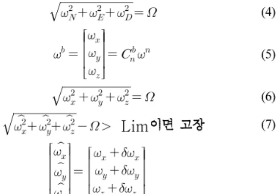
(7) .
.
(1)
(2)
(3)
(4)
(5)
(6)
Lim(7)
정렬위도 고장검출 기법 2.2
.
(
)
.
RLG
.
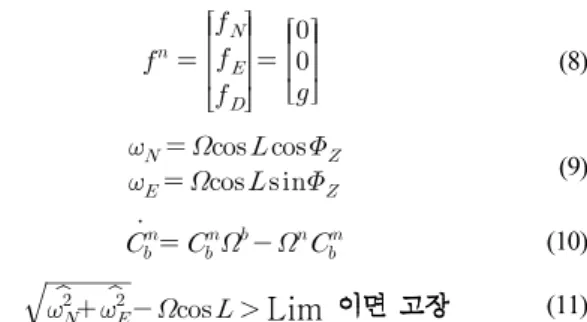
(8)
(9) .
(8) (9)
,
.
RLG
(10) .
(9) RSS
(11)
. 4
.
N
E
ˆE ˆN
Platform Frame: 실제적으로 항법계산이 이루어지는 좌표계
: small angle δψ
E 0 Ω =
N cosφ
Ω = Ω
ˆ ˆN cos cosφ δψ δβN
Ω = Ω ⋅ +
ˆ ˆE cos sinφ δψ δβE
Ω = Ω ⋅ + Azimuth Correction
ˆ
ˆ cos cos cos
cos (cos 1) ˆ
| cos (cos 1) | | ˆ | ˆ
N N N
c N
N N
N
φ δψ δβ φ
φ δψ δβ
φ δψ δ
δβ ω β
Ω − Ω = Ω ⋅ + − Ω
= Ω ⋅ −
Ω ⋅ − <<
=
+
≈
Mini-Bias
4. .
Fig. 4. Align latitude fault detection technique.
(8)
(9)
(10)
Lim(11)
가속도계 성능 고장검출 2.3
.
3
(2), (5)
(12) . (12) (8)
(2)
(13)
. (13)
.
(15) .
(14)
(16) . (16)
(16)
(17) . (17)
.
.
5 .
(12)
(13)
(14)
Lim (15)
Gravity measure
5. .
Fig. 5. Principle of Accelerometer fault detection.
(16)
(17) 관성센서뭉치 가속도계 고장검출
2.4
200 Hz .
.
관성센서뭉치 각속도 고장검출 2.5
200 Hz .
.
이용 가속도계 고장검출
2.6 FFT RLG/
RLG lock-in
400Hz 100 deg/sec .
[4].
3 RLG
.
3 RLG 400Hz
30 Hz 370, 400, 430Hz .
.
. RLG/
(18), (19) [4].
(18)
(19)
,
,
x, y, z RLG .
(18), (19) /
RLG/
RLG/
. RLG/
.
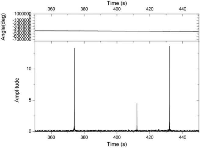
RLG/ FFT
6, 7 .
FFT RLG/
[4].
온도센서 고장검출 2.7
6
.
200 Hz
0.1 Hz
15 .
.
동작초기부터 고장이 존재하는 경우 2.7.1
. RLG/
3 RLG/
.
RLG/ 3
.
RLG/ .
동작중에 온도센서가 고장인 경우 2.7.2
. 온도센서 제한 범위 초과 고장 2.7.3
. 온도센서에 대한 고장배제 기능 2.7.4
1 3
.
.
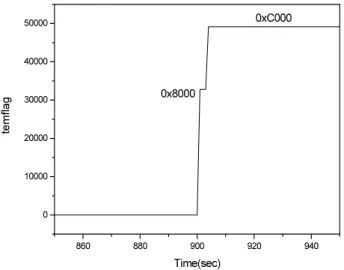
온도센서 고장검출 기법 검증 시뮬레이션 2.7.5
RLG/
.
900 Z
.
8~11 .
14 Z 15, 16 Z
“ ,
” , 8 “Z
”
11 “Z Y
” . 8~11
.
360 380 400 420 440
0 5 10
Time (s)
Amplitude
360 380 400 420 440
-7000000 -6000000 -5000000 -4000000 -3000000 -2000000 -100000010000000
Time (s)
Angle(deg)
6. X FFT .
Fig. 6. FFT result of measurements from X-axis accelerometer.
0 20 40 60 80 100
0.00 0.01 0.02 0.03 0.04 0.05 0.06
Time (s)
Amplitude
0 20 40 60 80 100
-250000 -200000 -150000 -100000-500000
Time (s)
Angle(deg)
7. X FFT .
Fig. 7. FFT result of measurements from X-axis gyroscope.
500 600 700 800 900 1000 1100 1200 1300 1400 1500 30
40 50 60 70 80 90 100 110 120
Accel. Temp
Time(sec)
X-Axis Accel. Temp.
Y-Axis Accel. Temp.
Z-Axis Accel. Temp.
8. Z .
Fig. 8. Temperature sensor fault of X-axis accelerometer.
860 880 900 920 940
0 10000 20000 30000 40000
50000 0xC000
temflag
Time(sec) 0x8000
9. .
Fig. 9. Fault detection result of temperature sensor.
500 600 700 800 900 1000 1100 1200 1300 1400 1500 -10
0 10 20 30 40 50 60 70
overflag
Time(sec) 0x0040
10. .
Fig. 10. Fault detection result of temperature output over measurement limit.
500 600 700 800 900 1000 1100 1200 1300 1400 1500 -2
0 2 4 6 8 10 12 14 16 18
isoflag
Time(sec)
0x0010