• 검색 결과가 없습니다.

Case Study : BIM for Planning, Simulating, and Implementing Complex Site Logistics

N/A
N/A
Protected

Academic year: 2021

Share "Case Study : BIM for Planning, Simulating, and Implementing Complex Site Logistics"

Copied!
6
0
0

로드 중.... (전체 텍스트 보기)

전체 글

(1)

Case Study : BIM for Planning, Simulating, and Implementing Complex Site Logistics

Kim, JongHoon

1)

・ Cohen, Fernando Castillo

2)

Received December 9, 2015 / Accepted December 21, 2015

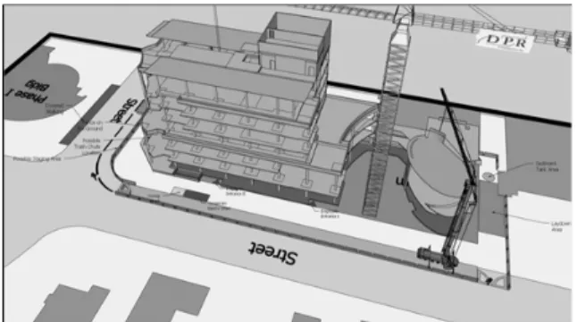
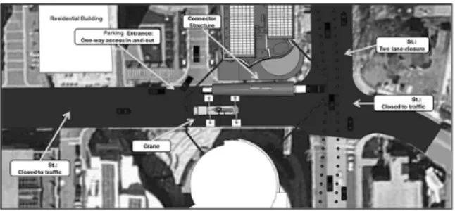
ABSTRACT: This paper presents a case study using Building Information Modeling (BIM) for planning, simulating, and implementing complex site logistics in a headquarter office building construction project in Silver Spring, MD. As part of the project a prefabricated 92ft structural tube steel pedestrian connector bridge was installed between two adjacent buildings in the city of Silver Spring, MD. There were multiple significant challenges to deliver, offload, prepare, and install the connector bridge safely, on time, and with the minimum disturbances to the neighbors. BIM was of the foremost importance to visualize, simulate, analyze, improve, and communicate the site logistics plan from delivery to installation of the connector bridge. As a result of the effort, GC of the project was able to prepare a highly detailed plan, communicate it effectively to all stakeholders, and flawlessly execute the work as planned. This case study would provide a useful reference for contractors who are seeking a better planning method that enables generation of more accurate, implementable, optimized plans for complex site logistics.

KEYWORDS: BIM, Site Logistics Planning, 4D, Collaboration, Integration

1)정회원, 삼성물산 건설부문, 공학박사 ([email protected]) (교신저자)

2)비회원, DPR Construction ([email protected])

DOI: http://dx.doi.org/10.13161/kibim.2015.5.4.047

1. BIM for Site Logistics Planning

Before BIM became popular, engineers created construction logistics plans from sequences of 2D drawings that described the management of 3D objects in space over time. These schematic drawings would examine the flow of resources (materials, equipment, vehicles, construction personnel, etc.). 2D site logistics planning is fine for visualization, but it’s limited in analyzing and optimizing the parts of the process. With 2D information only, it is difficult to com- prehensively check risks related to the missing dimension as engineers cannot fully understand 3D context of the site conditions. For example, it is not easy to show crane radius and height of the crane in one 2D drawing. Communicating site logistics plan with other project participants is also limited when a set of 2D drawings is used as the information in the separate drawings is not fully integrated.

With increased BIM use in the current AEC industry, computer models are being widely used for site logistics planning (Aslani and Chiarelli, 2009; Hergunsel, 2011;

Jianhua and Hui, 2010; Salazar et al., 2006; Said, 2010).

Planning site logistics in an accurate 3D model provides an added dimension to analyze and communicate site re- quirements with all project stakeholders, while streamlining the construction process.

For this case study, the site logistics model aided in the analysis of the following elements.

∙ Access routes by vehicle type into the construction site

∙ Areas designated as laydown and storage

∙ Project boundary fencing, curbing and vehicle control devices

∙ Major construction placement such as tower crane and concrete pump truck

∙ Means of emergency operation routes

∙ Parking and access routes from contractor parking to the construction site

∙ Job site office location

The site logistics plan was updated and remained

available for the duration of the project. There were several

logistics meetings held during the course of project devel-

(2)

Figure 1 3D view of the site logistics plan I

Figure 2 3D view of the site logistics plan II

Figure 3 3D view of the perimeter protection plan on 2nd floor

opment with all relevant parties in attendance to help define the initial and final logistics plan. The 3D model was beneficial to communicate ideas proposed by team members, and helped the project team analyze the impact of the site logistics plan on the entire project, as well as improve the quality of the plan. For example, the team used BIM for crane placement studies. Several different types of cranes were modeled with the dimensions and locations they would have in real life, allowing the team to identify obstacles within crane radius and ensure the crane reached the maximum extent required. The team could determine the most appropriate crane option based on this analysis. The BIM model also helped the team to understand the requirements for vertical flows during construction, an activity that is hard to con- ceptualize with 2D drawings. Using a 3D model that clearly depicted the curves, extrusions, and setbacks of the slabs helped the team find and compare places to locate the materials hoist, trash chute, and temporary structures like swing stages (Fig. 1 and 2).

In addition to showing the resource flow, the model was also used to describe, analyze, and communicate the safety plan. Figure 3 shows how the model was used to identify potential risk areas along the edge of slabs, slabs openings,

and illustrates the perimeter protection plan. The perimeter protection plan added value by providing clear visuals that everybody could easily understand to safeguard the site.

More value was added when the team added another dimension: time! The next section describes how the planning team was able to sequence the connector bridge delivery and installation by taking the site logistics model from 3D to 4D.

2. Tools for Site Logistics Planning

Trimble SketchUp (Trimble, 2013) was a convenient and popular tool used for site logistics planning for the following reasons.

∙ Easy to use (push and pull modeling)

∙ Use of existing libraries. It is easy to obtain generic components from 3D ware house available for public use. The general contractor who installed the connector bridge in this case study released SketchUp libraries including lots of SketchUp components needed for site logistic planning as well as their specific components like job trailers with the company’s logo.

∙ Interoperability with other BIM applications. SketchUp can import image files with different formats and BIM model in DWG format.

∙ Google Earth (Google, 2013) application: enables geolocation of the site/model, with a historical cache of 2D satellite images of the site and 3D terrain.

3. Connector Bridge Delivery and Installation

As part of the case study building project, a prefabricated

(3)

Figure 4 The connector bridge was installed on March, 11, 2012

Figure 5 Model of the delivery truck turning on to final road for unloading

92ft structural tube steel pedestrian connector bridge was installed between two adjacent buildings (Fig. 4). Among other applications of BIM for the site logistics planning in this project, the installation of the connector bridge took the most benefit out of BIM to address the multiple significant challenges to deliver, offload, prepare, and install the connector bridge safely, on time, and with the minimum disturbances to the neighbors. BIM was of the foremost importance to visualize, analyze, improve, and communicate the site logistics plan from delivery to installation of the connector bridge. As a result of the effort, the GC was able to prepare a highly detailed plan, communicate it effectively to all stakeholders, and flawlessly execute the work as planned.

The greatest challenge was to identify the best offload and laydown location for the connector bridge. Though it may sound trivial, this decision was critical because it significantly impacted the entire installation process in at least three important ways. First, the 139ft truck that delivered the connector bridge (all the way from Louisiana) had to be able to access the offload and laydown location. Second, the offload location had to result in minimum disturbances to traffic and neighbors during offload, installation, and throughout the 10 days of preparatory work in between.

And third, the location determined to a large extent the crane setup that would be required to lift the connector to its final installed position.

Several offload and laydown locations where initially proposed by the project team, but no consensus could be reached because nobody fully understood all the downstream consequences of the decision. This changed when the team decided to create a SketchUp model to clearly visualize,

analyze, and communicate the alternatives being considered for the different phases of the process.

The first challenge was to determine through which roads the 139ft truck could access the site. To test this, the team created a dimensionally accurate model of the delivery truck and overlaid the model to a scaled satellite image of the site.

In addition, the team utilized Proper Animation, a plug-in for SketchUp, to create 4D animations that allowed them to visualize exactly how the truck would approach each turn and identify any turns that would limit the truck’s access to the site. This exercise ruled out the possibility of using the back roads for access and it allowed the team to prove without a doubt that the truck could easily access the laydown location on after making the final turn from the main avenue (Fig. 5).

The 3D model and 4D animations added tremendous value by providing clear visuals everybody could rapidly understand. Equally important, the dimensional accuracy of the 3D model allowed the team to confidently plan how they would lay out all key logistic items and ens there would be enough space on site to execute the work as planned.

Furthermore, the model enabled the team to quickly explain the plan to other stakeholders and receive immediate high-quality feedback to adjust the plan in real time. Figure 6 and 7 show snapshots of the final logistics plan for the offload and laydown phase of the process.

The example above shows how the proposed plan

allowed the team to prove that access would remain open

to the Apartment Building entrance; that the 200 ton crane

would fit fully out-rigged next to the connector bridge and

truck; that only one lane would have to be closed on the

adjacent street; and that the access road would have to be

closed to through-traffic for the duration of this activity.

(4)

Figure 6 3D view of the logistics plan during the connector bridge offloading phase

Figure 7 Annotated 2D view highlighting the key logistics items during the connector bridge offloading phase

Figure 8 3D view of logistics plan during the 10 days of preparatory work between offload and installation

Figure 9 Visual analysis of maximum crane boom radius for different boom lengths

Similar snapshots were used to communicate the site logistics plan at all key phases of the project. For example, the next image shows a close-up view of the logistics plan used to communicate to neighbors and authorities how the 10 days of preparatory work on the connector bridge would impact traffic around the project (Fig. 8).

BIM was even more beneficial to analyze and plan the most critical phase of the project, the final pick and installation of the connector bridge. For this phase it was absolutely critical to determine exactly what kind of cranes were needed; where the cranes would need to be rigged to pick up the connector; and exactly how the cranes would safely maneuver the load to get it from its laydown position to its final installed position.

Even though a one-crane pick was preferred, the project team was inclined to do a two-crane pick because it was believed that given the project constraints a single crane could not perform the operation. However, before committing to a decision, the team used BIM to develop 4D simulations to explore potential alternatives that required only one crane. If successful, this would reduce cost, increase safety, and minimize traffic disruptions.

The 4D simulations allowed the team to test different

potential locations for the crane and analyze the precise paths required for the pick. In addition, the team used the model to analyze the load configuration at every key position during the lift to ensure the crane would be well within its load capacity at all times during the installation process and guarantee safety. Figure 9 shows a snapshot of the model being used to analyze the load’s path and the crane’s loading capacity. The transparent cylinder around the crane and the box around the boom show the maximum boom radius and length combination permitted to safely lift and install the connector bridge.

Before the lift plan could be approved, the team had to ensure the crane’s location did not impose an unacceptable load on any of the underground utilities. To test this, team used a scaled drawing of the site showing the underground utilities and overlaid the BIM model on top of it. This way the team was able to quickly and clearly prove that the proposed layout plan would not impact any of the under- ground utility lines (Fig. 10).

After testing multiple locations and resolving multiple

challenges, the team successfully identified a location

where a single 300 ton crane could be used to install the

connector bridge. Figure 11 shows the final site logistics plan

(5)

Figure 10 Underground utility coordination

Figure 11 Final lift

Figure 12 Crane and connector bridge with precise dimensions for final setup

Figure 13 Planned site logistics for the final pick of the connector bridge as developed using BIM

Figure 14 Actual site logistics after following the site logistics plan developed using BIM

for the installation phase.

Once the plan was reviewed and approved by all stakeholders, the team used the model to ens the work got executed as planned. As a final step, the team utilized the model to precisely lay out every critical logistics item in the field. Figure 12 shows a plan view of the crane and connector bridge with precise dimensions for field setup.

In the end, using BIM for site logistics planning proved to be a critical tool for the team’s success. BIM allowed the team to visualize, analyze, and communicate the site logistics plan and confidently execute the plan. Figure 13 shows a snapshot of the model developed during the planning phase. Figure 14 is a picture taken during installation. The resemblance is clear; the team planned the work and worked the plan.

4. Conclusion

The case study presented in this paper shows how BIM can be utilized for site logistics planning in construction projects. It demonstrates that added dimensions, 3D and 4D, increase the quality and comprehensiveness of site logistics planning as it allows for the planning team to share and communicate different ideas on the various locations of construction equipment, areas for material laydown and storage, and human routes. Compared to conventional 2D-based approach, application of BIM for site logistics planning also provides a better method to simulate and analyze the movement of cranes and their downstream consequences.

The case study also demonstrates that the usefulness of

the BIM application for site logistics planning can be

obtained only when the all the planning information under

considerations are reflected and integrated into a BIM model

and entire project team members participate in the planning

(6)

process using the BIM model. Use of simulation method in the case study also helped the participants recognize missing part of the participants’ initial plan. Generation of the simulation required complete set of information because it was not possible to move forward if there was any in- formation missing. Accordingly, the comprehensiveness of the bridge installation plan was increased.

Recent development of easy BIM modeling tools and number of reusable model components helps project planning team develop site logistics planning using BIM without putting extensive efforts.

However, analysis of the planning decisions and their downstream consequences in the case study are fully based on the visual analysis. The BIM model does not automatically detect problems or generate alternatives to resolve the problems. We expect further development of BIM tools in near future to enables the generation of alternatives based on computer-aided analysis of planning decisions.

Acknowledgments

We acknowledge DPR Construction for providing the case study in this paper.

References

Aslani, P., & Chiarelli, L. (2009), “Building information model:

the role and need of the constructors”, ASCE.

Google (2013), “Get the world’s geographic information at your fingertips”, “http://www.google.com/earth/index.html”

Hergunsel, M. F. (2011), “Benefits of building information modeling for construction managers and BIM based scheduling”, Doctoral dissertation, Worcester Polytechnic Institute.

Jianhua, C., & Hui, W. (2010), “Application and Popularizing of BIM Technology in Project Management”, E-Product E-Service and E-Entertainment (ICEEE), International Conference, pp. 1-4.

Salazar, G., Mokbel, H., Aboulezz, M., & Kearney, W. (2006),

“The use of the building information model in construction logistics and progress tracking in the Worcester trail courthouse”, Joint International Conference on Computing and Decision Making in Civil and Building Engineering, pp. 986-995.

Said, H. M. (2010), “Optimizing site layout and material logistics planning during the construction of critical infrastructure projects”, Doctoral dissertation, University of Illinois at Urbana-Champaign.

Trimble (2013), “The Easiest Way to Draw in 3D”,

“http://www.sketchup.com/”

수치

Figure 3  3D view of the perimeter protection plan on 2nd floor
Figure 5 Model of the delivery truck turning on to final road for  unloading
Figure 6 3D view of the logistics plan during the connector  bridge offloading phase
Figure  14  Actual  site  logistics  after  following  the  site  logistics plan developed using BIM

참조

관련 문서

This paper is a case study on how Venture and Small-Business Executives managers can take advantage of their intuitions in situations where the

Overall, international logistics service factors have a significant effect on satisfaction with international logistics services provided to trading companies,

A Study on Heat Dissipation Design and Performance Evaluation of Lithium-ion Battery Pack for Automated Logistics Robot Using Infrared Thermal Imaging

 James M. Els, “Strategic management of complex projects: a case study using system dynamics”, System Dynamics Review, Vol. Gordon, “Choosing appropriate

And for the case the entrapment is permitted, this study examines a few academic assumptions on the tolerance field, its theoretical grounds, ways to

This study aimed to evaluate the site and extent of injury, injury mechanism, player position, and the reinjury incidence in the hamstring by using magnetic

Lacey., Implementing an effective response management system: a white paper for 1995 International Oil Spill Conference... 작업부는 방제작업의

Purpose Model predictive controller for simulating closed-loop systems with hard bounds on manipulated variables and/or controlled variables using linear models in the MPC