Flow Analysis by CFD Model of Lifting System for Shallow Sea Test
Chi Ho Yoon
1), Jongmyung Park
1)*, Young Ju Kim
1), Yong Chan Park
1), Jung Seok Kang
1)and Seok-Ki Kwon
1)천해 양광시험을 위한 양광시스템의 CFD모델 유동해석
윤치호 · 박종명* · 김영주 · 박용찬 · 강중석 · 권석기
요 약 : 천해 양광시험을 위해 개발된 양광시스템에 대한 수치 해석이 CFD 모델에 의해 수행되었다. 본 연구에 서 양광펌프와 유연관의 유체유동은 FLUENT, 즉 상용화된 CFD모델을 이용하여 모사하였다. 펌프공동현상의 계산을 위해 유연관 길이와 펌프 수심의 두가지 경우가 선택되었다. 수치결과로부터, 볼텍스 유동이 첫단의 스테이터에서 관측되었고 계산된 NPSH는 양광펌프의 공동을 방지하기 위해 최소한으로 요구하는 조건을 만족 시키는 것으로 예측되었다.
주요어 : 양광시스템, CFD, 양광펌프, 유연관, NPSH
Abstract : Numerical study on a lifting system developed for shallow sea test is performed by a CFD model.
In this study, the flow behaviors in a lifting pump and flexible hoses is simulated by using FLUENT, a commercial CFD model. Two cases for calculation the pump cavitation behavior are selected according to the hose length and the depth of lifting pump. From the numerical results, it is found that the vortex flow is observed in the first-stage stator and the calculated NPSH meets the minimum required by a lifting pump based on the shallow sea environments.
Key words : Lifting system, CFD, Lifting pump, Flexible hose, NPSH
2009년 9월 29일 접수, 2010년 5월 31일 채택 1) 한국지질자원연구원
*Corresponding Author(박종명) E-mail; [email protected]
Address; Korea Institute of Geoscience and Mineral Resources
Introduction
The deep sea floor could be thought as the last treasury of mineral resources to be left for mankind. The developed countries have already driven forward actively the develop- ment of deep sea mineral resources in preparation for the on-land mineral resource exhaustion since 1960’s.
Especially, the successful development of deep sea mang- anese nodules requires developing exploration, mining and transfer technologies simultaneously, among which mining technology includes collecting and lifting tech- nologies of the manganese nodules (Chung, 1994; Yoon et al., 2009).
Lifting system is crucial to achieve the success of the deep-sea mining project, by which manganese nodules
are conveyed from the seafloor to the mining ship.
The conveying principle can be classified into the hydraulic pumping system and the air lift system according to the fluid dredging type, the continuous line buckets system of the mechanical type and the modular marine mining automation system (Yoon et al., 2001; Yoon et al., 2003; Yoon et al., 2007). Among the lifting methods, the hydraulic pump lifting system is situated between the buffer system and the lifting pipe that is connected to the mining ship (Yoon et al., 1998; Yoon et al., 1999).
The lifting pump, one of the core parts in the hydraulic pump lifting system, needs to be designed with multi- stages because it requires a high hydraulic head (Park et al, 2007). In Japan, an 8-stage lifting pump was developed for its offshore experiment (Chung, 1994). For the per- formance evaluation of the total lifting system, the flow characteristics of flexible hoses and lifting pipes are analyzed (Yoon et al., 2002; Yoon et al., 2003; Park et al., 2010).
연구논문
Fig. 1. Diagram of the lifting system.
Fig. 2. Diagram for the calculation area division of the pump.
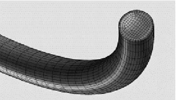
Fig. 3. Grids of the curved pipe.
Fig. 4. Calculation grid of lifting pump.
In this study, the simulations of the lifting pump and the connecting flexible hoses for shallow sea test have been conducted to guarantee the performance of the developed lifting pump using FLUENT, a commercial CFD model. The mining system consists of an underwater pump and flexible pipes in suction and discharge parts.
From the results, the flow characteristic of the system was analyzed to be used as basic data.
Modelling of the Mining System
The schematics of the lifting system are shown in Fig. 1. 1,2,3, in this figure, denote flexible hoses, a lifting pump and lifting pipes respectively. The target of the study is the hydraulic pumping system which is the two-phase lifting technology of solid and liquid.
The simulations were performed for two objectives: the prediction of flow structure in the pump and the total
analysis of the lifting performance. The total mining system was divided to perform the research efficiently and computational fluid analysis for the deduction of characteristic flow values of each part. An analytic method was employed to analyze the total system.
The pump was divided into two parts as in Fig. 2.
The outflow result of first part is employed as the entrance condition of second part.
The geometry of flexible hoses was presented in the Fig. 1. The curvature part as shown in Fig. 3 was meshed with the fine grids to predict head loss.
Numerical Method for Cfd
The CFD computations were run using the program Fluent, which employes the Finite Volume Method to solve the Navier-Stokes equations to predict the flow structure in the pump and the flexible pipes.
The hexahedral grid was employed for calculation.
Fine girds are constructed in the part close to the wall or in the part where the high gradients occur. In Fig.
stator rotor
Fig. 5. Pressure distribution [Pa].
Fig. 6. Velocity distribution [m/sec].
Fig. 7. Flowlines of the first stage stator.
Fig. 8. Flowlines of the second stage stator.
4, the calculation grid of the pump is shown.
The upwind-differenced scheme (Shih et al, 1995) was used for the discretization of the Navier-Stokes equations and the SIMPLE method was used for the pressure-velocity coupling (Barth et al., 1989). Realizable turbulent model was used for the turbulent flow structure. The standard wall function was employed for the turbulent flow boundary condition on the wall (FLUENT 6.3 user’s guide, 2008).
The energy equation was not solved because the working fluid is water and the temperature change is not severe.
We assumed it as non-compressible flow. The moving reference frame (Luo et al, 1994) model was used for the calculation time efficiency to acquire rotation speed of the pump impeller.
At a rotor inlet fixed flux as boundary condition is
given and pressure boundary at the exit of the second stage stator is designated as zero-static pressure. The entrance velocity was prescribed by changing from 1 CMM (cubic meter per minute, m3/min) to 2.5 CMM.
Because this range of velocity is chosen for working flow rate. The rotation of the pump rotor was fixed as 1,750 rpm. No slip condition and smooth walls are employed to solve the equations. All velocity conditions at the exit side of the rotor and the stator are employed as input for the calculation to acquire loss coefficients of the discharged part of the pump.
Results and Discussions
Simulation results of lifting pump
In Fig. 5 and Fig. 6, total pressure and velocity dis- tribution of the lifting pump are given. The input velocity is 5 m/sec. The total pressure increases when flow passes
Fig. 9. Flowlines at the discharged part of the pump.
Fig. 10. H-Q curve of the lifting pump.
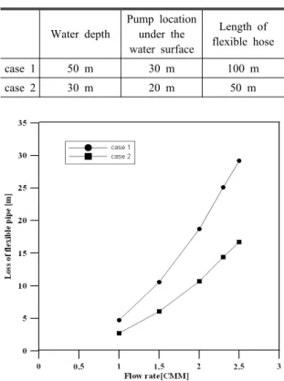
Table 1. Analysis conditions Water depth
Pump location under the water surface
Length of flexible hose
case 1 50 m 30 m 100 m
case 2 30 m 20 m 50 m
Fig. 11. head loss of the whole flexible pipe.
through the rotor and the stator, but velocity increases at the rotor and decreases at the stator. It is also shown that when flow at the exit of the rotor flows into the stator, the total pressure that increases at the rotor decreases.
In Fig. 7 and Fig. 8, flowlines at the stator of the first and second stage are represented. The flow that is accelerated at the rotor does not flow out smoothly from the stator and shows considerably complex flow distribution. The flow line at the blade suction side makes it possible to predict that considerable re-circulation areas will be formed toward span direction and hub side. It is thought that the outer side velocity becomes higher
as the discharged direction is toward radius and loss occurs due to separation and vortex in the vicinity of the center axis. The water flow into the stator is interrupted and distorted by this vortex.
Flowlines of the discharged part of the pump are shown in the Fig. 9. The rotational velocity component remains strongly even after the flow passes through the second stage stator and maintains from the rapid enlarging area at the back of the rotor until the water flows out through the discharged pipe. At this area, it is confirmed that considerable flow loss occurs, which are relatively low values in comparison with the loss that occurs at the first and the second stator.
Fig. 10 is the H-Q curve (Head-Discharge curve) of the pump that is predicted from the CFD analysis. X axis shows flow rate, and y axis indicates the total head.
Simulation results of the flexible pipe
For the computational convenience, we divided the whole flexible pipe into two parts. One is the severely
Fig. 12. Available and required pump hydraulic heads.
Fig. 13. Available and required efficiency suction hydraulic head.
curved part at the suction side and the other is assumed to be a linear part at the suction and the discharged side. Two cases in Table 1 were conducted for the case study according to the hose length and the position of lifting pump.
Fig. 11 shows the hydraulic head loss of the suction and discharged part of the whole flexible pipe. As flow quantity increases, the loss increases. Because case 1 is longer than case 2 in length, the loss is higher.
Calculation results for the whole system
Net Positive Suction Head, NPSH, shows the difference between the pressure and the liquid vapor pressure in that section. The following equation is used to calculate the required net hydraulic head for the whole system.
2 2
2 1 2 1
2 1
( )
required 2 loss
p p V V
H z z H
g g
ρ
− −
= + + − +
⋅
where p = pressure V = velocity z = altitude ρ = density
g = gravitational acceleration
And Hloss indicates the hydraulic head loss. Subscript 1 and 2 mean the inlet and the outlet of the pump.
In Fig. 12, the system efficiency curves (Hrequired :
required pump hydraulic head) under case 1 and case 2 conditions are shown together with the pump efficiency curve (Havailable: available pump hydraulic head). In the case 1 where water depth is deeper and the flexible pipe is longer than in case 2, it is estimated that the present pump has difficulty in transferring 2 CMM flow quantity, but in case 2, it is possible to transfer up to 2.5 CMM.
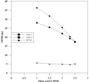
A calculation was performed to decide whether cavi- tation bubble occurs in the pump or not. In the present study, the net positive suction head calculation method was used instead of the cavitation model in the com- putational fluid analysis because it is well known and has better predictability. The required efficiency suction hydraulic head (NPSHrequired) was calculated on the basis of the computational fluid analysis results. The minimum pressure location in the pump can be perceived in the rotational rotor blade in the suction area. The operating pressure is controlled for the minimum pressure to be the saturated vapor pressure, where the pump entrance pressure is found to calculate the required efficiency suction hydraulic head. The available efficiency suction hydraulic head (NPSHavailable) was calculated from the energy equation of the system and the definition of the efficiency suction hydraulic head. In Fig. 13, the available and the required efficiency suction hydraulic head are
Fig. 14. NPSH where the pump is 10 meters (case 1) and 5 meters (case 2) up from the water level.
shown. It is expected that cavitation will not occur in case 1 or in case 2. Even when the pump location is lifted 10 meters up and it means that the pump location under the water surface is 20 m (case1) and 10 m (case2), all the flow conditions are calculated to have no pro- blems.
Fig. 14 is shown as in case of the pump lifted up:
10 meters from water level (case 1) and 5 meters (case 2). Even in case 1, it is estimated that cavitation will occur even in the flow rate of 2 CMM.
Conclusions
Numerical study on the lifting system developed for shallow sea test is conducted by using CFD to predict the flow structure in the pump and the pump location in the sea without cavitation. For the study of flow structure, the vortex flow is observed in the first-stage stator. The water flow into the stator is interrupted and distorted by this vortex. Two cases for calculation the pump cavitation behavior are selected according to the hose length and the depth of lifting pump. From the numerical estimation, it is found that the calculated NPSH meets the minimum required by a lifting pump based on the shallow sea environments.
References
Barth, T.J. and Jespersen, D., 1989, “The design and applica- tion of upwind schemes on unstructured meshes,” Technical Report AIAA-89-0366, AIAA 27th Aerospace Sciences Meeting, Reno, Nevada.
Chung, J.S., 1994, “Advanced in Deep-Ocean Mining Systems Research,” Proceedings of 4th International Offshore and Polar Engineering Conference, pp. 18-31.
FLUENT 6.3 user’s guide, 2008, pp. 12-61~12-65.
Luo, J.Y., Issa, R.I., and Gosman, A.D., 1994, “Prediction of Impeller-Induced Flows in Mixing Vessels Using Multiple Frames of Reference,” In IChemE Symposium Series, number 136, pp. 549-556.
Park, J.M., Yoon, C.H., Park, Y.C., Kim, Y.J., Lee, D.K., and Kwon, S.K., 2007, “Three Dimensional Solid-liquid Flow Analysis for Design of Two-stage Lifting Pump,”
Proceedings of The 7th ISOPE Ocean Mining Symposium, pp. 171-176.
Park, J.M. and Yoon, C.H., 2010, “Flow Structure for a Circular Cylinders with Exterior Surface Dimples,” Journal of The Korean Society for Geosystem Engineering, 2010, Vol. 47, No. 1, pp. 45-50.
Shih, T.-H., Liou, W.W., Shabbir, A., Yang, Z., and Zhu, J., 1995, “A New-Eddy-Viscosity Model for High Reynolds Number Turbulent Flows - Model Development and Vali- dation,” Computers Fluids, 24(3): pp. 227-238.
Yoon, C.H., Kim, I.K., Kwon, K.S., and Kwon, O.K., 1998,
“The Numerical Analysis of Particle Flow Patterns in pipe for Hydraulic pumping System in Deep-sea Manganese Nodules,” Journal of The Korean Institute of Mineral and Energy Resources Engineers, Vol. 35, No.2, pp. 157-164 Yoon, C.H., Kim, I.K., Kwon, K.S., and Kwon, O.K., 1999,
“Analysis of Unsteady State Flow Mechanism in Pipe for Hydraulic Pumping in Deep-Sea Manganese Nodules,”
Journal of The Korean Institute of Mineral and Energy Resources Engineers, Vol. 36, No. 1, pp. 33-41.
Yoon, C.H., Kwon, K.S., Kwon, S.K., Lee, D.K., Park, Y.C., and Kwon, O.W., 2001, “A Study on the Efficiency of an Air-Lift Pump for Pumping Solid Particles”, Journal of The Korean Institute of Mineral and Energy Resources Engineers, Vol. 38, No. 5, pp. 341-351.
Yoon, C.H., Lee, D.K., Kwon, K.S., Kwon, S.K., Kwon, O.K., Park, Y.C., and Sung, W.M., 2002, “The Effects of Pipe Curvature on the Flow Characteristics of Solid- liquid Two-phase Mixture in an Experimental Flexible Hose System,” Journal of The Korean Society for Geosystem Engineering, Vol. 5, No. 1, pp. 1-7.
Yoon, C.H., Lee, D.K., Park, Y.C., Kwon, S.K., and Kwon,
윤 치 호
1982년 한양대학교 자원공학과 학사 1988년 한양대학교 자원공학과 석사 1995년 한양대학교 자원공학과 박사
현재 한국지질자원연구원 책임연구원 (E-mail; [email protected])
김 영 주
1997년 한경대학교 기계공학과 공학사 1999년 성균관대학교 기계공학과 공학
석사
2003년 성균관대학교 기계공학과 공학 박사
현재 한국지질자원연구원 선임연구원 (E-mail; [email protected])
강 중 석
1979년 인하대학교 자원공학과 학사 1986년 인하대학교 자원공학과 석사
현재 한국지질자원연구원 책임연구원 (E-mail; [email protected])
박 종 명
현재 한국지질자원연구원 광물자원연구본부 선임연구원 (本 學會誌 第47券 第1号 參照)
박 용 찬
1993년 한양대학교 자원공학과 학사 1995년 한양대학교 자원공학과 석사 2000년 한양대학교 자원공학과 박사
현재 한국지질자원연구원 선임연구원 (E-mail; [email protected])
권 석 기
1983년 서울대학교 지질학과 이학사 1986년 서울대학교 지질학과 이학석사 1998년 서울대학교 지질학과 박사과정
현재 한국지질자원연구원 지질기반정보연구부 선임연구원 (E-mail; [email protected])
O.K., 2003, “Flow Characteristics of Solid-Liquid Two-Phase Mixture in a Flexible Pipe,” Journal of The Korean Society for Geosystem Engineering, Vol. 6, No. 1, pp.
7-12.
Yoon, C.H., Park Y.C., Lee, D.K., Kwon, K.S., and Kwon, S.K., 2003, “Hydraulic Pumping Test System of KIGAM for Deep-Sea Manganese nodules,” Proceedings of 33rd Underwater Mining Institute, pp. 131-135.
Yoon, C.H., Park Y.C., Kim, Y.J., Park, J.M., and Kwon,
S.K., 2007, “A Study on Flow Analysis of Lifting Pump and Flexible Hose for Sea-Test,” Journal of The Korean Society for Geosystem Engineering, Vol. 44, No. 4, pp.
1-6.
Yoon, C.H., Park, Y.C., Park, J.M., Kim, Y.J., Kang, J.S., and Kwon, S.K., 2009, “Solid-liquid Flow Experiment with Real and Artificial Manganese Nodules in Flexible Hoses,” International Journal of Offshore and Polar Engineering, Vol. 19, No. 1, pp. 77-79.
![Fig. 6. Velocity distribution [m/sec].](https://thumb-ap.123doks.com/thumbv2/123dokinfo/5177333.595252/3.799.438.698.504.706/fig-velocity-distribution-m-sec.webp)