서 론 .
Ⅰ
(retinal prosthesis), (artificial heart),
(functional electrical stimulator, FES), (implantable hearing aids)
[1-4].
임형규1, 이장우1, 김동욱1, 이정현2, 성기웅3, 김명남4, 조진호3,5
1 ,
2 ,
3 ,
4 ,
5 IT ,
Implementation of a Transcutaneous Power Transmission System for Implantable Medical Devices by Resonant Frequency Tracking Method
H. G. Lim1, J. W. Lee1, D. W. Kim1, J. H. Lee2, K. W. Seong3, M. N. Kim4, J. H. Cho3,5
1Graduate School of Electrical Engineering and Computer Science, Kyungpook National University
2Department of Biomedical Engineering, Kyungpook National University Hospital
3Advanced Research Center for Recovery of Human Sensibility, Kyungpook National University
4Department of Biomedical Engineering, School of Medicine, Kyungpook National University
5School of Electronics Engineering, College of IT Engineering, Kyungpook National University (Received June 21, 2010. Accepted September 6, 2010)
Recently, many implantable medical devices have been developed and manufactured in many countries. In these devices, generally, energy is supplied by a transcutaneous method to avoid the skin penetration due to the power wires. As the most transcutaneous power transmission methods, the electromagnetic coupling between two coils and resonance at a specific frequency has been used widely. However, in case of a transcutaneous power transmitter with a fixed switching frequency to drive an electromagnetic coil, inefficient power transmission and thermal damage by the undesirable current variation may occur, because the electromagnetic coupling state between a primary coil and a secondary coil is very sensitive to skin thickness of each applied position and by person. In order to overcome these defects, a transcutaneous power transmitter of which operating frequency can be automatically tracked into the resonance frequency at each environment has been designed and implemented. Through the results of experiments for different coil surroundings, we have been demonstrated that the implemented transcutaneous power transmitter can track automatically into a varied resonance frequency according to arbitrary skin thickness change.
Implantable medical device, transcutaneous power transmission, electromagnetic coupling, resonant frequency tracking
Corresponding Author : 조진호
대구광역시 중구 동인동 가2 101경북대학교 의학전문대학원 신관 층5 N509 첨단감각기능회복장치연구소
Tel : +82-53-427-5538 / Fax : +82-53-427-5539 E-mail : [email protected] & [email protected]
본 연구는 보건복지가족부 보건의료기술진흥사업의 지원에 의하여 이루어진 것임 과제고유번호( : A092106).또한 이 논문은2010년 교육과학기술부로부 터 지원받아 수행된 연구임 지역거점연구단육성사업 노화극복 웰빙을 위한( / · 융합의료기술개발사업단).
, 2 .
.
(electromagnetic coupling) (transcutaneous power transmission)
[5-6].
1 2
1 2
. 1
2 ,
.
.
.
. ,
1 .
. (near magnetic field)
2
.
Guoxing Wang
, 2
1 [7-8].
.
(phase locked loop, PLL) [9].
,
. PLL VCO (voltage
controlled oscillator)
.
PLL .
PLL .
.
(ACROSS, Korea) [10].
.
공진 주파수 추적을 이용한 무선전력전달 .
Ⅱ
전자기 결합의 기본 원리 A.
1 2
Secondary coil Rechargeable battery Signal processor Electromagnetic flux
Transcutaneous power transmitter
Primary coil
Implantable microphone
Vibration transducer
Out of the body In the body
Secondary coil
Primary coil
Skin
그림1. 무선전력전달 기능을 가진 완전 이식형 인공중이 장치의 구조 Fig. 1. The schematic of F-IMEHD with a transcutaneous power transmitter.
그림2. 1, 2차 송수신 코일 결합에 대한 기하학적 구조 Fig. 2. A geometric formation of a primary coil and a secondary coil.
.
(resonant converter)
. 1
(fully implantable middle ear hearing device, F-IMEHD) [11].
1
.
. 1, 2
LC (quality factor, Q)
. 2
.
,
Eq. (1) Eq. (3)
.
1 , 2 [12].
.
(1)
(2)
(3)
. LC
, .
, 1
.
, .
.
공진 주파수 추적법 B.
,
. 3
. ,
.
H .
, 1
1 LC
2
. 1
.
2
. ,
Out of the body (power transmitter) Skin In the body (power receiver) Vcc
Rectifier
Charger
Battery Secondary coil
RMS detector
Micro- controller
Waveform generator H-bridged
coil driver
Primary coil A/D
그림3. 주파수 추적 기능을 가지는 피부 투과형 전력 전송 장치의 블럭도
Fig. 3. Block diagram of the transcutaneous power transmission with frequency tracking function.
PLL PLL
. LC
(root mean square, rms) ,
.
.
A/D ,
LC
. 4 ,
.
1. LC
, 1
. 2.
. 3.
.
4. ,
.
5. .
실험 및 결과 .
Ⅲ
, (ACROSS)
.
실험 장치의 구성 A.
1 .
. 0.4 [13].
, H ,
. 2
2
Primary coil Secondary coil
External diameter 22 mm 22 mm
Internal diameter 8.8 mm 8.8 mm
Turns 25 25
Inductance 12.5
H 12.5
HResistance 1.2
1.0
Material of magnet NdFeB NdFeB
표1. 제안한 전력전달방법에 사용된 송수신 코일의 사양 Table 1. Specifications of coil for the proposed power transmission.
START
The tracked frequency
Frequency step up
Frequency step down New current
< old current
Frequency step up
New current
< old current
New current
< old current
Frequency step down
Frequency step up
END
No No
No Yes
Yes
Yes
그림4. 제안한 무선전력전달 장치를 위한 주파수 추적법의 순서도 Fig. 4. Flow chart of the frequency tracking method for the proposed
transcutaneous power transmitter.
5 . 5 mm
152 kHz 130
~ 200 kHz 1 kHz .
B. 실험결과
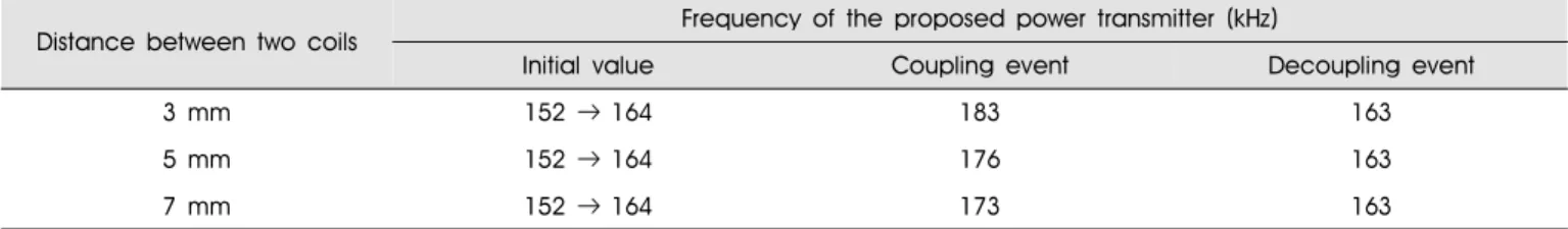
3, 5, 7 mm
. LC
. 6
,
LC . 2
. 152 kHz
164 kHz ,
. ,
.
.
결 론 .
Ⅳ
1 2
. ,
,
. ,
.
F-IMEHD
Power transmitter Primary coil with
magnet
그림5.제안한 주파수 추적 기능을 가진 무선전력전달 장치의 송신부와 전 력 수신부를 포함한 완전 이식형 인공중이 장치의 구현 모습 Fig. 5. The implemented transcutaneous power transmitter with a frequency
tracking function and F-IMEHD with a power receiver.
Distance between two coils Frequency of the proposed power transmitter (kHz)
Initial value Coupling event Decoupling event
3 mm 152→164 183 163
5 mm 152→164 176 163
7 mm 152→164 173 163
표2. 코일 간격의 변화와 수신 코일의 유무에 따라 제안한 무선전력전달 장치가 추적한 공진주파수
Table 2. The tracked resonant frequency of the proposed power transmitter according to existence of a secondary coil.
Coupling event sections
140 Decoupling event sections
120
100
80
60
40
A number of enviroment's variation
0 1 2 3 4 5 6 7 8 9 10 11 12 13 14 15 16 17 Frequency tracking sections
Initial frequency
3mm 5mm 7mm
그림6.코일 간격의변화와코일의 결합 또는 비결합이반복됨에따라제안 한 무선전력전달 장치의 주파수 추적 경향을 나타낸 그래프; (a) 3 mm, (b) 5 mm, (c) 7 mm
Fig. 6. A tendency of frequency tracking using the proposed power transmitter according to alternation between coupling and decoupling at several distances between coils; (a) 3 mm, (b) 5 mm, and (c) 7 mm.
.
LC
.
.
참고문헌
[1] W. Liu and M.S. Humayun, “Retinal prosthesis,” IEEE International Solid-State Circuits Conference, vol. 1, pp.
218-219, 2004.
[2] M. Takahashi, K. Watanabe, F. Sato, and H. Matsuki, “Signal transmission system for high frequency magnetic telemetry for an artificial heart,” IEEE Transactions on Magnetics, vol. 37, no. 4, pp. 2921-2924, 2001.
[3] W. Mayr, M. Bijak, D. Rafolt, S. Sauermann, E. Unger, and H.
Lanmuller, “Basic design and construction of the Vienna FES implants: Existing solutions and prospects for new generations of implants,” Medical Engineering Physics, vol. 23, pp. 53-60, 2001.
[4] H.H. Kim and D.M. Barrs, “Hearing aids: A review of what’s new,” Otolaryngology Head and Neck Surgery, vol. 134, pp.
1943-1050, 2006.
[5] W.C. Brown, “The history of wireless power transmission,” Solar Energy, vol. 56, no. 1, pp. 3-21, 1996.
[6] H. Matsuki, Y. Yamakata, N. Chubachi, S. Nitta, and H. Hashimoto,
“Transcutaneous DC-DC converter for totally implantable
artificial heart using synchronous rectifier,” IEEE Transactions on Magnetics, vol. 32, no. 5, pp. 5118-5120, 1996.
[7] G. Wang, W. Liu, R. Bashirullah, M. Sivaprakasam, G.A. Kendir, Y. Ji, M.S. Humayun, and J.D. Weiland, “A closed loop transcutaneous power transfer system for implantable devices with enhanced stability,” in Proceedings of the International Symposium on Circuits and Systems 2004 (ISCAS ’04), Santa Cruz, USA, May 2004, vol. 4, pp. 17-20.
[8] G. Wang, W. Liu, M. Sivaprakasam, G.A. Kendir, “Design and analysis of an adaptive transcutaneous power telemetry for biomedical implants,” IEEE Transactions on Circuits and Systems, vol. 52, no. 10, pp. 2109-2117, October 2005.
[9] C.H. Lin and J.Y. Chen, “The tracking of the optimal operating frequency in a class E backlight inverter using the PLL technique,” IEICE Transactions on Electronics, vol. E88-C, no.
6, pp. 1253-1262, October 2005.
[10] J.H. Cho, I.Y. Park, and S.H. Lee, “Development of fully-implantable middle ear hearing device with differential floating mass transducer: Current status,” Journal of Biomedical Engineering Research, vol. 26, no. 5, pp. 309-317, October 2005.
[11] I.Y. Park, H.G. Lim, Y.H. Yoon, M.K. Kim, B.S. Song, and J.H.
Cho, “A transcutaneous recharging system with the function of bi-directional signal transmission for fully implantable middle ear hearing devices,” IEICE Transactions on Fundamentals of Electronics, Communications and Computer Sciences, vol.
E89-A, no. 6, pp. 1692-1694, June 2006.
[12] C.M. Zierhofer and E.S. Hochmair, “Geometric approach for coupling enhancement of magnetically coupled coils,” IEEE Transactions on Biomedical Engineering, vol. 43, no. 7, pp.
708-714, July 1996.
[13] S. Atluri and M. Ghovanloo, “Design of a wideband power- efficient inductive wireless link for implantable biomedical devices using multiple carriers,” in Proceedings of the 2nd International IEEE EMBS Conference on Neural Engineering, Arlington, Virginia, USA, March 2005, pp. 533-537.