pISSN 1598-2033 eISSN 2233-5706
Comparative Performance Analysis of Robot-based Automated Construction System Using a Real Scale Test Project
11
0
0
전체 글
(2)
(3)
(4)
(5)
(6)
(7)
(8)
(9)
(10)
(11)
수치
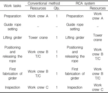
![Figure 2. Comparison of fabrication method [12]](https://thumb-ap.123doks.com/thumbv2/123dokinfo/5124537.578876/4.892.67.412.681.1089/figure-comparison-of-fabrication-method.webp)

+5
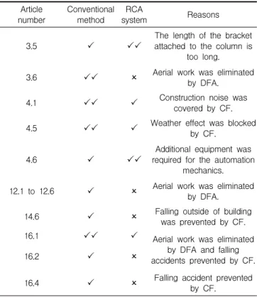
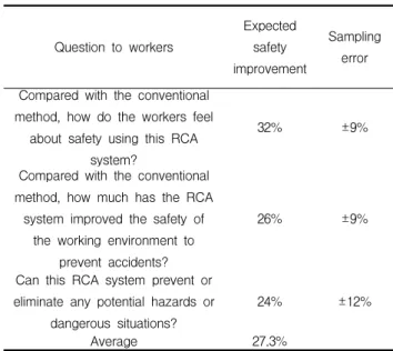
![Table 7 lists the eight root causes of construction accidents[25] and the expected results when the RCA system is used in a construction project](https://thumb-ap.123doks.com/thumbv2/123dokinfo/5124537.578876/8.892.59.420.775.1063/table-causes-construction-accidents-expected-results-construction-project.webp)
관련 문서
– A fixed lump-sum price based on the quantities provided by the owner for the major components of the project. – Most infrastructure projects and
– Organizational support for safety education (e.g. orientation, training, workshops, etc.) for all level of project members – Regular safety meetings and daily toolbox
Resource Based Construction Rate Work Based. Construction
Embedded commands: database commands are embedded in a general-purpose programming language.. Library of database functions: available to the host language for
It is built as the automated fruit warehouse management system based on the wireless sensor network in the fruit warehouse through the RFID/USN can use
제주도 기후변화 특성 분석집.. 1) ASOS: Automated Synoptic Observing System 2) AWS: Automatic
KEY WORDS: Electric propulsion system 전기추진시스템; Energy Management System 에너지 관리시스템; Load Control System 부하제어시스템; Load analysis 부하분석... 이산화탄소
❑ What peer review does best is improve the quality of published papers by motivating authors to submit good quality work – and helping to improve that work through the
