Manuscript received on May 29, 2019, Accepted on July 23, 2019
1 KEPCO Research Institute, Korea Electric Power Corporation, 105 Munji-ro Yuseong-gu, Daejeon 34056, Korea
Electrochemical Performance of a Metal-supported Solid Oxide Electrolysis Cell
Taehee Lee
1, Sang-Yun Jeon
1, Young-Sung Yoo
1†Abstract
A YSZ electrolyte based ceramic supported Solid Oxide Cell (SOC) and a metal interconnect supported SOC was investigated under both fuel cell and co-electrolysis (steam and CO
2) mode at 800°C. The single cell performance was analyzed by impedance spectra and product gas composition with gas chromatography(GC). The long-term performance in the co-electrolysis mode under a current density of 800 mA/cm
2was obtained using steam and carbon dioxide (CO
2) mixed gas condition.
Keywords: Solid Oxide Fuel Cells, Reversible Solid Oxide Cells, Metal Interconnect, Synthesis Gas, Co-electrolysis
I. INTRODUCTION
In recent years, due to the fossil fuel crisis and global warming, there has been a push to expand clean energy sources as well as increasing demands for carbon dioxide capture and its storage/utilization technology. Solid oxide fuel cells(SOFCs) for clean energy generation systems have attracted significant attention [1][2]. Selectivity and flexibility of SOFCs for fuel use have expanded from large scale power plants to the smaller power units such as the distributed generation system [3]-[5]. With a concept similar to the SOFC, reversible solid oxide cells(RSOCs) have generated interest for the development of energy storage and electricity generation [6][7], because a RSOC system can provide effective power delivery system and has an efficient electrical energy storage device for use in power plants [8].
The RSOC system can also make renewable energy using steam electrolysis [9]. Fig. 1 shows a schematic of the principle RSOC mode under different conditions at the electrodes during operation. High temperature electrolysis of steam (H
2O) and carbon dioxide (CO
2) (Co-electrolysis, Co-EC, H
2O + CO
2→ H
2+ CO + O
2) using renewable energy sources has emerged as a new ESS technology [10]. Thus, developing suitable electrolyte and electrode materials is a key issue in RSOC development [11][12].
Current studies on high-temperature CO
2/steam co- electrolysis mainly focus on materials development, system design, economic analysis, performance and durability of single cells and stacks [13]-[23]. For the RSOC, the choice of an oxygen electrode has been important, as the major contributor toward the overall cell polarization resistance [24]. As a result, a number of materials, such as (La
0.75Sr
0.25)
0.95MnO
3, La
0.8Sr
0.2MnO
3(LSM) and the La
0.8Sr
0.2FeO
3, LSM-YSZ compound and the Sm
0.5Sr
0.5CoO
3- Sm
0.2Ce
0.8O
1.9composite [25][26], have been used as an oxygen electrode in the RSOC. Cobalt-based perovskite materials are a potential oxygen electrode material in the RSOC system for their high catalytic activity and oxygen permeability. However, they suffer the drawback of reaction with the electrolyte during operation at high temperature [27]
and delamination from the electrolyte surface.
In this study, we fabricated a ceramic supported SOC integrated with a metal interconnect by a joining process.
This integrated form with a metal interconnect was
developed to make a more compact size and eliminate a
sealing problem during the stack integration. We inserted a
barrier layer between the electrolyte and air electrode to
prevent delamination. We analyzed the electrochemical
performance by electrochemical impedance spectroscopy
(EIS).
II. EXPERIMENTAL
For the fabrication of the ceramic supported cells, Ni and yttria stabilized zirconia (YSZ) composites were used with a weight ratio of 50:50. For a pore former, graphite power (24 vol%) was employed with sufficient porosity. This NiO+YSZ powder mixture was then uniaxially pressed into an anode substrate and pre-sintered at 1,400°C for 1 hour. Then the Ni- YSZ, YSZ electrolyte was coated using slurry coating and sintered at 1,550°C for 2 hours. Before coating of the oxygen electrode, samarium stabilized zirconia (SDC) was adjusted as a buffer layer on the YSZ surface by screen printing and heated for 1 hour at 1,250°C. For the air electrode, La
0.6Sr
0.4Co
0.2Fe
0.8O
3(LSCF6428) was made by screen printing and heated for 1 hour at 1,100°C. The effective area of the air electrode was set to 0.5 cm
2(diameter: 0.8 cm). A schematic
of the cell and the fabricated cell are shown in Fig. 2.
The metal supported SOC was prepared and adjusted for integration with metal interconnects without an oxygen electrode layer. A ferritic stainless steel (STS) 430 plate was adjusted as a metal interconnect with 2.0 mm thickness and 28 mm diameter. The fuel supply channel was designed in a serpentine shape. To attach the metal interconnect on the ceramic electrode, bonding slurry was used with a NiO, YSZ and STS 430 powder mixture. This bonding slurry was adjusted on both the metal interconnect and fuel electrode side sintered at 1,400°C for 2 hours in a reducing atmosphere with Ar valance 4% hydrogen gas. LSCF6428 was used for an air electrode. The effective area of the cathode was set to 0.636 cm
2. The oxygen electrode of the metal supported SOC was heated in air during cell operation. Fig. 3 shows photographs of the metal supported SOC.
Fig. 1. Schematic representation of process occurring during the operation in SOFC and RSOC.
Fig. 2. Cross section schematic view and photograph of the fabricated ceramic supported SOC.
(a) (b)
Fig. 3. Photograph of metal-supported electrolysis cell. (a) air electrode side. (b) metal interconnect side.
Fig. 4. Schematic diagram of the co-electrolysis (water steam and carbon dioxide) test system.
We evaluated the current-voltage (I-V) and electro- chemical performance. The I-V test used an electrical load (KIKUSUI PLZ-4W) and digital multi-meter (KEITHLEY 2400) and the electrochemical performance was analyzed using a Solartron 1287 potentiostat / galvanostat and 1260 impedance/gain phase analyzer. For the fuel cell test, hydrogen gas mixed with 3% steam was supplied as fuel with flow rate of 100 cc/min and 250 cc/min of air flowed to the cathode side. The long-term performances in an electrolysis mode were monitored at a constant current density of 0.8 A/cm
2at 800°C for about 350 hours (total). The cell was operated in a galvanostatic mode with the current load operating for 1 hour at each galvanostatic measurement. The outlet gas composition was analyzed using a gas chromatograph (HP-Agilent 6890) at the hydrogen electrode side during each galvanostatic operation.
III. RESULTS AND DISCUSSIONS
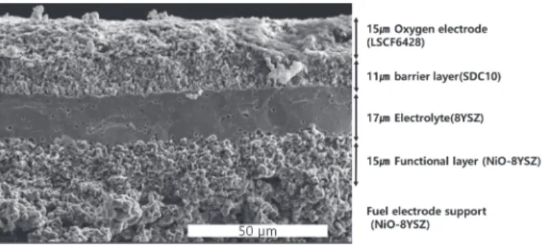
The cross-sectional SEM image of the ceramic supported SOC is shown in Fig. 5. There were no observable internal cracks between the electrode and the electrolyte. This image indicated that the dense SDC barrier layer was in good contact with the air electrode and the electrolyte layer
The performance in the SOFC mode at 800°C is show in Fig. 6. The open circuit voltage (OCV) was show 1.1 V and the maximum power density (MPD) was 1.16 W/cm
2at 800°C.
Fig. 6(a) shows impedance spectra of the button cell. As can be seen, the impedance spectrum consisted of two elongated arcs. The impedance spectrum consisted of two elongated arcs which are accompanied with a high frequency intercept on the real axis. The high frequency intercept was due to ohmic resistance, mainly from the electrolyte, whereas the elongated arcs corresponded to electrode polarization phenomena. Generally, it is common practice to use equivalent circuit fitting to the calculate area specific resistances from the EIS data. However, this process involves the use of a predefined equivalent circuit without any knowledge about the polarization subprocesses, and therefore it may lead to ambiguous or incorrect conclusions.
In future studies, to avoid any such ambiguity, the DRT of the impedance data will be performed to isolate the subprocesses that contribute to the electrode phenomena as a function of temperature and time.
The concept of solid oxide electrolyzer cells is H
2generation and carbon sequestration by the electrolytic reduction. Furthermore, the co-electrolysis of steam/CO
2to produce syngas enables a unified and ingenious solution obtained from the steam/CO
2co-electrolysis utilizing the electricity and heat from carbon-free sources in the Fischer- Tropsch process. To produce this syngas composition, we studied the most important parameter which can be controlled is the upstream gas composition. The ceramic supported SOC was continuously run in SOFC and Co-EC
Fig. 5. A cross section SEM image of the ceramic supported SOC.
Fig. 6. Impedance spectra and I-V characteristics of the ceramic- supported SOC.
Fig. 7. Impedance spectra and I-V curves of ceramic supported SOC with Co-EC mode.
Fig. 8. Impedance spectra and I-V characteristics of the metal-supported SOC in the FC mode.
modes to test its reversibility in different CO
2and H
2O gas ratios. Fig. 7 shows the impedance spectra and performance of the ceramic supported SOC during ROSC operations with several gas mixtures at the fuel electrode side at 800°C. The ohmic and total resistance shows similar behavior, even with different gas conditions at OCV conditions as shown in Fig.
7(a). The I-V characteristics were nearly constant after each different gas composition, indicating that the SOC can work well in several H
2-CO
2-H
2O-CO environments. There was no observable effect of the gas-diffusion limitation at higher current densities.
Fig. 8 shows a typical impedance and I-V curve of the metal supported SOC under FC mode operation. As can be seen, compared with the ceramic supported SOC, the maximum power density of the metal supported SOC has a
value similar to the ceramic supported SOC. However, in the metal supported SOC, at a high current density, the voltage sharply decreased due to a huge concentration polarization whereas this did not occur in the ceramic supported SOC. We have not yet determined the main reason for this difference and we only estimated it by the different gas supplying conditions in both types of SOC. We also observed these phenomena by impedance spectroscopy. The ohmic resistances were similar between the ceramic supported SOC and the metal supported SOC, but the arc of low frequency at the metal supported SOC was higher than the value of the ceramic supported SOC. From this difference, we could estimate that the gas path was not enough to supply gases well at the fuel side. Moreover, compared with different types of cell, the power density had similar behavior before the mass transport limitation.
The performance of the metal supported SOC during Co- EC mode operation was different from that of the ceramic supported SOC (Fig. 9(b)). In the metal supported SOC, a huge concentration polarization occurred like in the FC mode operation. The concentration polarization also appeared in the impedance results. Resistance at the low frequency was four times higher than in the ceramic supported cell.
Moreover, the oxygen electrode degradation was more serious because the oxygen gas evolved in the air electrode side, thereby easily causing a gas build-up at the interface.
Because, the air electrode did not have pre-heat treatment for robust adhesion, the aforementioned interface was subject to more significant damage than that of the SOC.
Table 1 shows the variation in H
2content and CO content with various current densities for two kinds SOC cells in the outlet gas composition during galvanostatic measurements at 800°C in 35% N
2, 5% H
2, 20% CO
2and 40% H
2O conditions.
In both types of cells, when the current density initially increased, H
2flux increased significantly over that of CO flux proving that at the applied current density, the steam electrolysis was easier than CO
2electrolysis, because the voltage required for the electrolysis of steam was lower than that of CO
2electrolysis. At higher current densities, although there was a clear increase in CO flux, the H
2flux remained nearly unchanged. The two types of cell demonstrated similar gas flux with various current densities.
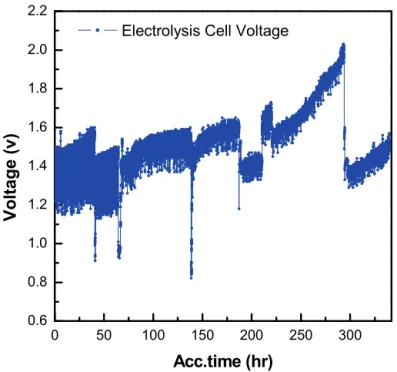
Nevertheless, our metal supported SOC was almost constant in long-term performance (Fig. 10) during the co- electrolysis of CO
2(45 ml/min) and H
2O (2.2 ml/hr). Fig. 10 shows a fairly stable cell voltage over 200 hours at 800°C under a constant current density of 0.8 A/cm
2. However, there
(a) (b)
Fig. 9. (a) Impedance spectra and (b) I-V characteristics of both types of SOC during the Co-EC operation at 800°C with an H2/N2/CO2/H2O gas mixture..
Fig. 10. Long-term performance in the Co-EC mode of the integrated SOC with metal interconnect at 800°C under a constant current density at 800°C.
0 50 100 150 200 250 300
0.6 0.8 1.0 1.2 1.4 1.6 1.8 2.0 2.2
Vo ltage (v )
Acc.time (hr) Electrolysis Cell Voltage
Table 1
Variation of hydrogen and CO fluxes during galvanostatic measurement with different current densities of both types SOC cells.
Current density Ceramic supported SOC Metal supported SOC
H2 CO H2 CO
0 A/cm2 12.76% 3.87% 10.40% 3.80%
0.3 A/cm2 13.90% 4.04% 11.80% 3.50%
0.6 A/cm2 14.38% 4.58% 12.60% 4.64%
0.8 A/cm2 14.68% 5.07% 13.10% 5.01%
was an increasing voltage at a constant current in the SOC performance after 200 hours, which could have occurred because there was not enough steam supply because the syringe pump was empty in water. When the steam was resumed, the voltage revived but the rate of degradation slightly increased and the microstructural would be damaged due to the shortage of steam.
IV. CONCLUSION
In our study, a ceramic supported SOC integrated with a metal interconnect by a joining process (Ferritic stainless steel, STS 430) was successfully developed. Comparing the electrochemical performance, we found that the maximum power density in the FC mode metal supported SOC was slightly higher than that of the ceramic supported SOC.
However, the metal supported SOC performed well in Co-EC operation and was stable for over 300 hours.
REFERENCES
[1] Singhal S. C. and Kendall K., "High Temperature Solid Oxide Fuel Cells:
Fundamentals, Design and Applications," Elsevier, 2003.
[2] Minh N. Q. and Takahashi T., "Science and Technology of Ceramic Fuel Cells," Elsevier, 1995.
[3] Larminie J. and Dicks A., "Fuel Cell Systems Explained, 2nd Edition," John Wiley & Sons Ltd, 2003.
[4] O'Hayre R, Cha S. W., Colella W. and Prinz F. B., "Fuel Cell Fundamentals,"
pp. 3-8, John Wiley & Sons, 2006.
[5] Yoo Y.-S., Lee T., Choi J. H., Park T.-S., Oh J.-M., and Kim C.-Y., "Fabrication and Demonstration of 1kW class SOFC stack and system for residential power generation application," J. Fuel Cell Sci. Technol 6(2), 021008-13, February, 2009.
[6] Larminie J. and Dicks A., "Fuel Cell Systems Explained, 2nd Edition," John Wiley & Sons Ltd, 2003.
[7] Minh N. Q., "Development of reversible solid oxide fuel cells (RSOFCs) and stacks," ECS Trans., 35, 2897-2904, May 2011.
[8] Ren J., Gamble S. R., Roscoe A.J., Irvine J. T. S. and Burt G., "Modeling a reversible solid oxide fuel cell as a storage device within AC power networks," Fuel Cells, 12(5), 773–786, July 2012.
[9] Ni M., Leung M.K.H., Leung D.Y.C., "Technological development of hydrogen production by solid oxide electrolyzer cell (SOEC)," Int. J.
Hydrogen Energy 33(9), 2337-2354, May 2008.
[10] Choi J. H., Lee T., Choi M., Yoo Y.-S., Baek S.-W. and Bae J., "Long-term performance of anode-supported SOFC integrated with metal interconnect by joining process," Int. J. of Hydrogen Energy, 35(9), 4285–4291, May 2010.
[11] Mawdsley J.R., Carter J.D., Kropf A.J., Yildiz B. and Maroni V.A., "Post-test evaluation of oxygen electrodes from solid oxide electrolysis stacks,"
Int. J. Hydrogen Energy 34(9), 4197-4207, May 2009.
[12] Virkar A.V., "Mechanism of oxygen electrode delamination in solid oxide electrolyzer cells," Int. J. Hydrogen Energy 35(18), 9527-9543, September 2010.
[13] Kim-Lohsoontorn P. and J. Bae, "Electrochemical performance of solid oxide electrolysis cell electrodes under high-temperature coelectrolysis of steam and carbon dioxide," J. Power Sources, 196(17), 7161-7168, September 2011.
[14] Li S., Li Y., Gan Y., Xie K. and Meng G., "Electrolysis of H2O and CO2 in an oxygen-ion conducting solid oxide electrolyzer with a La0.2Sr0.8TiO3+δ
composite cathode," J. Power Sources, 218(15), 244-249, November 2012.
[15] Yue X. and Irvine J. T. S., "(La,Sr)(Cr,Mn)O3/GDC cathode for high temperature steam electrolysis and steam-carbon dioxide co- electrolysis," Solid State Ionics, 225(4), 131-135, October 2012.
[16] Graves C., Ebbesen S. D., Mogensen M. and Lackner K. S., "Sustainable hydrocarbon fuels by recycling CO2 and H2O with renewable or nuclear energy," Renew. Sustain. Energy Rev., 15(1), 1-23, January 2011.
[17] Ebbesen S. D., Graves C. and Mogensen M., "Production of Synthetic Fuels by Co-Electrolysis of Steam and Carbon Dioxide," Int. J. Green Energy, 6(6), 646-660, December 2009.
[18] Fu Q., Mabilat C., Zahid M., Brisse A. and Gautier L., "Syngas production via high-temperature steam/CO2 co-electrolysis: an economic assessment," Energy Environ. Sci., 3(10), 1382-1397, May 2010.
[19] O’Brien J. E., McKellar M. G., Harvego E. A. and Stoots C. M., "High- temperature electrolysis for large-scale hydrogen and syngas production from nuclear energy – summary of system simulation and economic analyses," Int. J. Hydrogen Energy, 35(10), 4808-4819, May 2010.
[20] Stoots C., O’Brien J. E. and Hartvigsen J. "Results of recent high temperature coelectrolysis studies at the Idaho National Laboratory,"
Int. J. Hydrogen Energy, 34(9), 4208-4215, May 2009.
[21] O’Brien J. E., McKellar M. G., Stoots C. M. Herring J. S. and Hawkes G. L.,
"Parametric study of large-scale production of syngas via high- temperature co-electrolysis," Int. J. Hydrogen Energy, 34(9), 4216-4226, May 2009.
[22] Wang W. S., Huang Y. Y., Jung S., Vohs J. M. and Gorte R. J., "A Comparison of LSM, LSF, and LSC for Solid Oxide Electrolyzer Anodes," J.
Electrochem. Soc., 153(11), A2066-A2070, September 2006.
[23] Yang C., Adam C. and Chen F., "High temperature solid oxide electrolysis cell employing porous structured (La0.75Sr0.25)0.95MnO3 with enhanced oxygen electrode performance," Int. J. Hydrogen Energy, 35(8), 3221- 3226, April 2010.
[24] Kong J., Zhang Y., Deng C. and Xu J., "Synthesis and electrochemical properties of LSM and LSF perovskites as anode materials for high temperature steam electrolysis," J. Power Sources, 186(2), 485-489, January 2009.
[25] Liang M., Yu B., Wen M., Chen J., Xu J. and Zhai Y., "Preparation of LSM–
YSZ composite powder for anode of solid oxide electrolysis cell and its activation mechanism," J. Power Sources, 190(2), 341-345, May 2009.
[26] Jiang W., Lu Z., Wei B., Wang Z. H., Zhu X. B., Tian Y. T., Huang X. Q. and Su W. H., "Sm0.5Sr0.5CoO3–Sm0.2Ce0.8O1.9 Composite Oxygen Electrodes for Solid Oxide Electrolysis Cells," Fuel Cells, 14(1), 76-82, February 2014.
[27] Yu B., Zhang W. Q. and Xu J. M., "Microstructural characterization and electrochemical properties of Ba0.5Sr0.5Co0.8Fe0.2O3−δ and its application for anode of SOEC," Int. J. Hydrogen Energy, 33(23), 6873-6877, December 2008.