A Study on the Heat Transfer Enhancement of Miniature loop Heat Pipes by Using the Cu Nanofluids
Young-Sik Kim*, Hyo-Min Jeong**, Han-Shik Chung**, Md.Riyad Tanshen***†, Dae-Chul Lee***, Myoung-Kuk Ji**** and Kang-Youl Bae*****
(received 4 November 2011, revised 21 February 2013, accepted 6 March 2013)
Abstract:An experimental study was carried out to understand the heat transfer performance of a miniature loop heat pipes using water-based copper nanoparticles suspensions as the working fluid. The suspensions consisted of deionized water and copper nanoparticles with an average diameter of 80 nm.
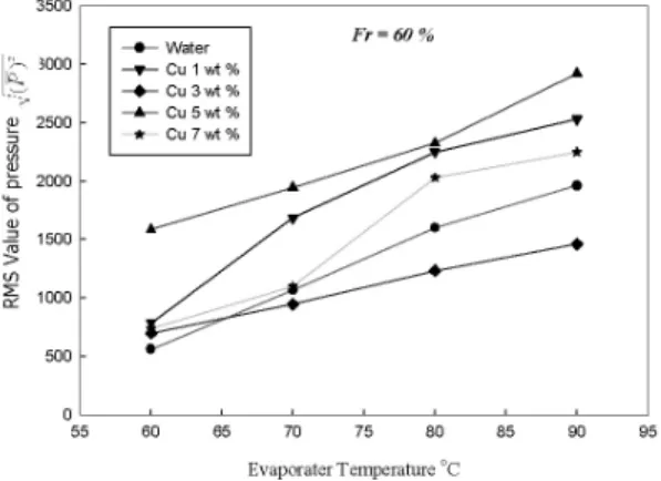
Effects of the cupper mass concentration and the operation pressure on the average evaporation and condensation heat transfer coefficients, the critical heat flux and the total heat resistance of the mLHPs were investigated and discussed. The pressure frequency also depends upon the evaporator temperature which has been maintained from 60 o C to 90 o C. The Investigation shows 60% filling ratio gives the highest inside pressure magnitude of highest number pressure frequency at any of setting of evaporator temperature and 5wt% results the lowest heat flow resistance.
Key Words:Miniature loop Heat Pipe, Pressure Fluctuation, Heat flow resistance, Nanofluid
*** † Md.Riyad Tanshen (corresponding author) : Department of Energy and Mechanical Engineering, Gyeongsang National University.
E-mail : [email protected], Tel :+8210-24603444
*Young-Sik Kim : Incheon campus Korea Polytechnics Department of Industrial Facility Automation.
**Hyo-Min Chung, Han-Shik Chung : Department of Energy and Mechanical Engineering, Institute of Marine Industry, Gyeongsang National University.
****Myoung-Kuk Ji : Young Jin Forging Co., Ltd.,
*****Kang-Youl Bae : Dae Myung GENT Co., Ltd.,
***Dae-Chul Lee : Department of Energy and Mechanical Engineering, Gyeongsang National University.
1. Introduction
A Loop heat pipes (LHPs) is a type of heat transfer system used in heat recovery systems.
LHP is preliminarily used for cooling and controlling the temperature of electronic devices which may be classified in special category of heat
pipes. The complexity of microchip has been increasing at the rate of factor of 2 per year over the past several decades. The number of transistors on a chip has increased to as many as 500 billion transistors packed on a single chip. The further miniaturization of electronic devices is leading to greater chip packing densities and thus higher chip power densities. The new challenge in the field is on removal of large quantities of heat quickly and efficiently from chip in order to keep chip temperature within an operational range. LHPs phenomena carry a great role in the field of heat transfer to control heat transfer into micro cavity.
The LHPs that is driven by the fluctuation of
pressure waves occurs much more and quick heat
transfer from one end to another. The pressure
fluctuation occurs because of nucleate boiling by
evaporative section and condensation of the working
fluid. The article shows all about vertical orientation of miniature loop heat pipes. The research concentrates on the pressure characteristics inside the miniature loop heat pipes. Extended investigations of LHPs have been investigated since the first development of Loop heat pipes (LHPs) originates from 1972, when the first such device with a length of 1.2 m and capacity of about 1 kw, with water as working fluid, was created and tested successfully by the Russian scientists Gerasimov and Maydanik from the Ural Polytechnical Institute 1-2) . Loop heat pipes (LHPs) are highly efficient heat-transfer devices with a considerable potential for development and application in various fields. At present LHPs are successfully employed in space engineering 3) . Past works over LHPs can be concluded within several features like heat transfer characteristics and capability with different filling ratio, flow visualization inside LHPs, effects of length ratio and diameter on performance of LHPs, nanofluid and other applicable fluids has been used as working fluid for developing LHPs performance.
Gi et al. conducted flow visualization for closed-loop PHP made from Teflon tube of 2 mm internal diameter and partially filled with R142b.
The PHP consisted of 10 meandering turns and it is 400 mm from the evaporator to condenser. The evaporator was heated by a hot bath and the condenser was cooled by a cold bath. It was concluded that the best thermal performance for the PHP is achieved when the FR is from 0.5 to 0.6 4) .
In S. Suresh et al. using Al₂O₃-Cu/ water hybrid nanofluids with volume concentration from 0.1 to 2% 5) . 1998 Chandratilleke et al. developed the cryogenic loop heat pipes. The development of cry cooler cooled superconducting magnets applications, where heat transport distance is large, and the heat conduction by a copper block will be constrained by its cross section transport capacity 6) . Q. Mo et al. shows that the heat transport capacity of loop
heat pipe with liquid nitrogen as working fluid is very low- only 26 W hen it operates in horizontal direction and its lowest thermal resistance reaches 1.3 K/W, which is too high for most of cryogenic heat transport system 7-8) . V. G Pastukhov et al. The first of them had as its aim demonstration of the limiting possibilities of mLHP with design characteristics suitable for application in PC and Analogous electronic devices 9) . Yu. F. Maydanik loop heat pipes a decrease in pressure losses in the adiabatic section of LHPs is ensured by the fact that for the motion of a working fluid here use is made of separate smooth-walled pipe-lines, which exclude both the thermal and the viscous interaction between counter flows of vapor and liquid 10) .
The work has much more new investigations about mLHP comparing previous works. The pressure characteristics and the influence of nanoflud concentration on pressure fluctuation into mLHP has been. It is well known that the heat transfer by miniature loop heat pipe occurs for quick fluctuation of pressure intensity but it can be hardly found some works over pressure distribution inside mLHP. The work with copper nanofluid and pressure behaviors drag a different dimension to this article.
2. Experimental setup
2.1 Experimental Apparatus and Procedure
The experimental apparatus (shown in Fig. 1)
consists of a miniature loop heat pipe, water heater,
cooling bath and data acquisition system. The heat
pipe is made by copper and acrylic tube with the
same inner diameter of 8 mm having the loop
length of 725 mm. The mLHP setup was oriented
vertically and the downward loop section with the
length of 100 mm was submerged into the
evaporative section. Evaporative temperature was
kept constant by flowing hot water heated by tube
type heater with digital control system.
Similarly the 100 mm of upper loop section was inserted through the condensing tank and kept sealed. Condenser temperature was maintained within 18℃ to 20℃ by using isothermal cooling unit. In the middle of this mLHP 525 mm acrylic adiabatic section was covered by 2 cm thick glass wool to insulate this section thermally. T-type thermocouple was soldered to the outer wall of mLHP in both condensing and evaporative sections to measure the wall temperature of mLHP. After setting temperature of evaporative section temperature of evaporative fluid gets stable. One piezoresistive absolute pressure sensor (Model- Kistler 4045A5) is set with another small by pass tube coming out from condensing section of mLHP to catch the pressure characteristics inside the tube.
Fig. 1 Schematic diagram of Experimental Setup and Real Experiment photo.
The sensor was perfectly sealed and tested several times. Using lab view program with the help of computer all the pressure data has been acquired after getting the system stable. Data acquisition rate was 100 data /sec and data taking duration was about 10 min. To find out the frequency distribution FFT analysis has been with 10240 data and the experimental measurement error
2%. For the convenience of understanding a part of real experimental setup has been shown.
2.2 Preparation of Nanofluid
The copper nanoparticles with mean diameter of 80 nm was (collected from NTi Npowder, Daejeon South Korea) used to make nanfluid suspension.
The purity of Dark brown copper nanofluid was 99.9% and two step method is used to disperse nanoparticle into base fluid. Base fluid was distilled water and no pH changers or surfactants were used to make dispersion. Ultrasonic vibrator (Sonic Vibra-Cell VC-130PB) generating ultrasonic pulses of 130 W at 20 kHz were used for 2 hr in every individual dispersion process.
a) 1wt% b) 3wt% c) 5wt% d) 7wt%
Fig. 2 Photo of different wt% nanofluids sample .
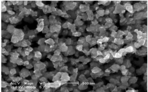
Fig. 3 SEM image of copper particle with average diameter(80-100) nm
The percentage of nanoparticles in the base fluid was in the range of 1% to 7% in weight. Fig 2.
Shows the physical observation of different weight
percentage nanofluid. It can be seen that with
increasing particle concentration the color of nanofluids gets more darker. Fig 3. shows a SEM (Scanning Electron Microscope) image containing copper nanoparticles with average size of 80nm- 100nm.Table 1 shows 30℃ thermo physical propertics water and Cu nanofluids.
Table 1 Thermo physical propertics
Materials
Thermal Conductivity W.
C.P J/kg.K
water 0.6176 4.179387
Cu 401 387
3. Data Reduction
Receiving thousands of raw data signal in the form of voltage it has been converted into pressure and analyzed to find mean and RMS value in following way
Mean Pressure, N t P P
N
i mean
∑ =
= 1 ) (
(1)
N is total number of data recorded in a period of time (i =1.2.3………N)
Pressure fluctuation (Prms) or rms value of u component expressed in eq. (2)
RMS value, N
t P P P
P
N i
mean rms
∑ =
−
=
= 1
2 2
)]
( [
(2) Where =10240
The overall heat flow resistance (R T/T ) has been calculated for constant wall temperature following the equation given below
(3)
Where R is a dimensionless parameter and it
expresses the thermal resistance and , ,
are average mLHP wall temperature in evaporator, average mLHP wall temperature in condenser and average hot water temperature supplied to evaporative section respectively.
4. Results and discussion
The heat input in the evaporator, filling ratio of working fluid as well as the shape, diameter, angle of installation have great influences on performance of miniature loop heat pipe. The influence of particle weight fraction on heat transfer is also concern to study nanofluids. The all above mentioned parameters are interrelated with inside pressure fluctuation for the best performance of mLHP.
Evaporator Temperature
oC
60 70 80 90
He at flow r es istanc e, R
T/T0.0 0.2 0.4 0.6 0.8
Fr = 40%
Fr = 60%
Fr = 80%
Fig. 4 Water heat flow resistance of heat pipe at different filling ratio
Fig. 4 presents the effect of different filling ratio on thermal resistance at various operating evaporative temperatures where the working fluid is distilled water. Here it can be shown that the lowest heat flow resistance has been achieved at 60% filling ratio at any evaporative temperature.
With increasing the evaporative temperature heat
flow resistance is decreasing for 60% and 80%
filling ratio. But in case of 40% filling ratio heat flow resistance increases with increasing evaporative temperature because of low volume ratio that does not capable to carry more heat until the pick of condensing section of mLHP. Besides the mass of fluid is too small in amount that brings only less amount of heat to condenser that’s why the temperature difference between evaporator and condenser is so small. In case of 80% filling ratio more fluids makes much vapor plug on the pick and did not have a feasible space to ease the heat transfer. Because of more vapor plug in case of 80% filling ratio the driving force for the oscillation and transportation of heat from the evaporator to the condenser is decreased.
Fig. 5 Temperature distribution of condensing wall at various evaporative temperature
So 60% filling ratio facilitates the optimum conditions in mass and in volume to transport more heat from evaporative section that minimizes thermal resistance and maximizes heat transfer through mLHP. For 60% filling ratio, Fig. 5 shows temperature distribution at condensing section gets higher with increasing evaporative temperature.
Pressure and temperature increases with passing time and with increasing evaporative temperature.
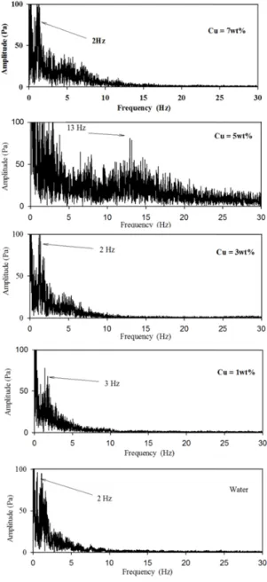
Similarly in fig. 6 – It can be shown that pressure
Fig. 6 Pressure distribution into OHP at various evaporative temperatures
wt%
0 1 2 3 4 5 6 7 8
Hea t flo w res is ta nce, R
T/T0.0 0.1 0.2 0.3 0.4 0.5 0.6
TE = 600C TE = 800C TE = 900C