반도체및디스플레이장비학회지 제7권 제4호(2008년 12월)
Journal of the Semiconductor & Display Equipment Technology, Vol. 7, No. 4. December 2008.
41
Orthorhombic-NiSi/Si (010)
구조의 Pd 치환 연구: 제 1 원리 계산
김대희·김대현·서화일*·김영철†
†한국기술교육대학교 신소재공학과, *정보기술공학부
Study of Pd substitution in orthorhombic-NiSi/Si (010) structure:
First principles calculation
Dae-Hee Kim, Dae-Hyun Kim, Hwa-Il Seo* and Yeong-Cheol Kim†
†Department of Materials Engineering,
*School of Information Technology, Korea University of Technology and Education
ABSTRACT
NiSi is less stable than the previously-used CoSi2 at high temperature. Some noble metals, such as Pd and Pt, have been added to NiSi to improve its thermal stability. We employed a first principles calculation to understand the Pd segregation at the interface. An orthorhombic structure of NiSi was used to construct an orthorhombic-NiSi/Si (010).
Lattice parameters along a- and c-axes in orthorhombic-NiSi were matched with those of Si for epitaxy contact. The optimized 1×4×1 orthorhombic-NiSi (010) and 1×2×1 Si (010) superstructures were put together to construct the orthorhombic-NiSi/Si (010), and the superstructure was relieved in calculation to minimize its total free energy. The optimized interface thickness of the superstructure was 1.59Å. Pd atom was substituted in Ni and Si sites located near interface. Both Ni and Si sites located at the interface were favorable for Pd substitution.
Key Words : First principles calculation, orthorhombic-NiSi, interface, Pd substitution
1. 서 론
금속 실리사이드(metal silicide)는 접합과 국부적인 연결, 또는 저항 및 신뢰도를 향상시키기 위해 ultra- large scale integration(ULSI) 기술에 사용되어오고 있 다[1]. 니켈 실리사이드(nickel monosilicide, NiSi)는 낮 은 저항, 좋은 확산 배리어(barrier) 성질, 낮은 공정 온 도, 낮은 실리콘 소모량 등의 이유로 90 nm 이하의 ULSI에서 구현되고 있는 실리사이드 물질 중에 하나 이다[2].
하지만, NiSi는 티타늄 실리사이드(titanium disilicide, TiSi2)와 코발트 실리사이드(cobalt disilicide, CoSi2)보다 열 안정성이 열악하다[3]. 최근에 NiSi의 열 안정성을 개선시키고자 금속을 첨가한 연구가 활발히 진행되고 있다. Y. -C. Kim은 laser-assisted local-electrode atom-
probe(LEAP)를 이용하여 NiSi/Si(001)에 Pd 원자가 첨 가된 Ni1-xPdxSi/Si(001)(x = 0.05) 구조를 연구하였다 [4]. 이 연구는 Ni1-xPdxSi/Si(001)의 계면 쪽으로 Pd 원 자가 편석(segregation)되는 것을 보고하였으며, 이 결 과는 Pd 원자가 벌크에 존재하는 Ni 자리에 치환되는 것 보다 계면을 선호한다는 것을 보여준다.
최근에, 제 1 원리 계산(first principles calculation)을 이용한 NiSi/Si 구조의 계면 연구가 보고되었다. D. - H. Kim은 NiSi의 B2 구조를 이용하여 B2-NiSi/Si 초 격자구조와 Pd 원자를 치환한 연구를 보고하였다 [5- 6]. 하지만 NiSi의 B2 구조보다 orthorhombic 구조가 에너지 관점에서 더욱 안정하다.
본 연구는 에너지 관점에서 안정한 orthorhombic- NiSi 구조를 선택하여 Si 기판과 접합시켜 orthorhombic- NiSi/Si(010) 초격자구조를 계산하고 Pd을 치환하여 실 험적 결과와 일치하는지 확인하였다. 또한 Pd 원자가 치환되면 어떤 자리를 선호하는지 고찰하였다.
†E-mail : [email protected]
42 김대희·김대현·서화일·김영철
반도체및디스플레이장비학회지 제7권 제4호, 2008
2. 계산 방법
본 연구는 Vienna ab-initio Simulation Package(VASP) 코드로 구현된 first principles local density approximation (LDA)을 이용하여 수행되었다 [7-9]. 사용된 포텐셜 (potential)은 projector-augmented wave(PAW)이며, 전자 의 바닥 상태를 계산하기 위하여 residual minimization method direct inversion in the iterative subspace(RMM- DIIS)가 사용되었다[10-11]. 계산 시간을 단축하고, 전 이 금속이 포함된 실리사이드 물질을 계산한 연구를 바탕으로 LDA를 사용하였다[12]. 사용된 cutoff energy 는 500 eV이고, k-points mesh는 Monk-horst pack이며, orthorhombic-NiSi/Si(010) 구조의 표면에 진공을 넣었 기 때문에 4x1x4 크기가 사용되었다. Smearing 방법은 Gaussian 계산법이 사용되었으며, smearing factor는 0.05 eV가 사용되었다. 사용된 cutoff energy와 k-points mesh 값은 계산 시간과 계산 값의 정확도를 적절히 조 절한 최적화된 값이다.
Si 기판과 에피택시 접합(epitaxy contact)을 위해서
orthorhombic-NiSi 단위 격자의 a와 c 축의 길이를 각 각 6.16 %, -1.36 % 변형시켜 Si의 격자 상수와 동일 하게 하였다. 변형된 orthorhombic-NiSi(010)과 Si(010) 이 접합된 10Å의 진공 두께를 포함한 orthorhombic-
NiSi/Si(010) 초격자구조를 생성하여 안정한 구조를 계
산하였다. 최적화된 초격자구조에 Ni 원자 자리와 Si 원자 자리에 Pd 원자를 치환하여 에너지 관점에서 가 장 안정한 자리를 확인하였다. 본 연구에서 사용된 전하 분포는 visualization for electronic and structural analysis
(VESTA)를 이용하여 분석되었고, 이 때 사용된
isosurface level은 0.063이다[13]. Isosurface level은 a03(a0=보어 반경) 부피당 전하량을 의미한다.
3. 결과 및 고찰
Fig. 1은 Si과 tetragonal 구조로 변형된 orthorhombic- NiSi를 보여준다. Mij(M = Si, Ni)에서 i는 초격자구조의 계면으로부터 멀어지는 층의 순서(양수는 NiSi 방향, 음수는 Si 방향)를 의미하고, j는 i 층에서 각각 다른 위치를 갖는 원자를 의미한다.
Fig. 1. Planar view of (a) Si (010) and (b) orthorhombic- NiSi (010) along [010] direction. Light grey and black (yellow and blue in color) spheres are Ni and Si atoms, respectively.
Fig. 2. Planar view of orthorhombic-NiSi/Si (010) super- structure along [100] direction. Grey (red in color) box shows the charge density at the interface of the superstructure.
Orthorhombic-NiSi/Si (010) 구조의 Pd 치환 연구: 제 1 원리 계산 43
Journal of KSDET Vol. 7, No. 4, 2008 Fig. 2는 tetragonal 구조로 변형된 1×4×1 orthorhombic-
NiSi(010)와 1×2×1 Si(010)이 접합된 orthorhombic- NiSi/Si(010) 초격자구조를 보여준다. 계면 근처에 존재 하는 Si 원자는 Ni 원자보다 orthorhombic-NiSi(010) 내부의 원자 구조와 다르게 Si 기판 쪽으로 이동한 것 을 알 수 있다. 이는 orthorhombic-NiSi(010)의 Si 원자 와 Si(010)의 Si 원자가 Si-Si 결합 거리를 유지하기 위 해서이다. Si(010) 내부에서, Si-Si 결합 거리는 2.34Å 이다. Orthorhombic-NiSi/Si(010) 초격자구조의 계면에 위치한 Si-Si 결합이 3개 존재하고, 결합 거리는 각각 2.63Å(Si11-Si-14 결합), 2.47Å(Si12-Si-11 결합, Si12-Si-15
결합)으로 내부의 Si-Si 결합 거리와12.39%, 5.56% 정 도 차이를 갖는다. 또한 초격자구조의 계면에서, Ni-Si 결합도 존재하는데 이 때의 결합 거리는 2.31Å(Ni11- Si-14 결합), 2.19Å(Ni12-Si-15 결합)으로 orthorhombic- NiSi(010) 내부의 Ni-Si 결합 거리(2.24Å)보다 각각 3.13, -2.23 % 정도 차이를 갖는다.
Pd 원자가 Si과 Ni 원자 자리에 치환되었을 경우에 대한 에너지 변화는 아래 식으로 정리할 수 있다.
EPdSi= (ENi(SiPd)/Si+ ESi) – (ENiSi/Si+ EPd) (식 1-1) EPdNi= (E(NiPd)Si/Si+ ENi) – (ENiSi/Si+ EPd) (식 1-2) 위 식에서 ENi(SiPd)/Si와 E(NiPd)Si/Si는 Pd 원자가 Si 또 는 Ni 자리에 치환되었을 때의 에너지, ENiSi/Si(-315.28 eV)는 orthorhombic-NiSi/Si(010) 초격자구조의 에너지, ESi(-5.96 eV)과 ENi(-6.51 eV), EPd(-6.42 eV)는 Si과 Ni, Pd 원자의 에너지 값이다. Table 1은 식 1-1과 1-2에 입력되는 ENi(PdSi)/Si와 E(NiPd)Si/Si의 에너지 값이다.
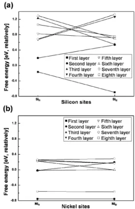
Fig. 3는 Table 1, 식 1-1, 그리고 1-2를 이용하여 Pd 원자가 orthorhombic-NiSi/Si(010) 초격자구조에 각각 의 Si과 Ni 원자 자리에 치환될 때의 에너지 값을 보여
준다. Pd 원자가 orthorhombic-NiSi/Si(010) 초격자구 조의 Si 원자 자리에 치환될 때, 계면에 존재하는 Si 원자 자리에 치환되는 것이 내부에 치환되는 것보다 에너지 관점에서 더욱 안정하였다(Fig. 3(a)). 또한 초 격자구조의 계면에 존재하는 두 개의 Si 원자 자리 중 에서 Si12 원자 자리에 치환되는 것이 에너지 관점에서 더 안정하였다. Fig. 3(b)는 Pd 원자가 초격자구조의 Ni 원자 자리에 치환되었을 때의 에너지 값을 보여준 다. Ni 원자 자리에 Pd 원자가 치환되면 Si 원자 자리 에 치환되는 것과 동일하게 초격자구조의 계면에 편석 된다. 하지만 표면에 존재하는 Ni 원자 자리에 Pd 원 자가 치환되면 Si 원자에 Pd 원자가 치환될 때와 다른 경향을 보인다. 표면에 존재하는 Ni 원자 자리에 Pd 원자가 치환되면 계면에 존재하는Ni 원자 자리에 치환 되는 것과 유사하게 표면에도 편석된다. Pd 원자가 초 격자구조의 계면에 편석되는 것은 Y. -C. Kim의 실험 적 결과와 동일하다 [4]. 하지만, Y. -C. Kim은 Pd 원 자가 초격자구조의 계면에 치환되면 어떤 원자 자리를 Table 1. Free energies of Pd substitution into Si and Ni sites
in orthorhombic-NiSi/Si (010) superstructure.
Sii1 Sii2 Nii1 Nii2
i = 1 -315.91 -316.43 -315.94 -315.94 i =2 -315.54 -315.20 -315.20 -314.99 i =3 -314.51 -315.19 -315.21 -315.19 i = 4 -315.06 -314.47 -314.96 -315.02 i = 5 -314.92 -315.02 -314.93 -315.02 i = 6 -314.44 -315.04 -314.96 -315.19 i = 7 -315.05 -314.41 -314.93 -314.90 i = 8 -314.68 -314.98 -315.75 -315.76
Fig. 3. Energy variation of the systems with Pd substitution to different (a) Si and (b) Ni sites from the ortho- rhombic-NiSi/Si (010) superstructure using equation (1-1) and (1-2). Pd prefers the interfacial site to the inside.
44 김대희·김대현·서화일·김영철
반도체및디스플레이장비학회지 제7권 제4호, 2008 선호하는지는 실험분석 결과의 정밀도 한계로 밝히지 는 못했다.
또한 D. -H. Kim은 B2-NiSi/Si(001) 초격자구조에 Pd 원자가 치환되면 계면에 편석된다고 보고하였는데, B2-NiSi의 terminating 층에는 Ni 원자만 존재하여 Si 원자 자리에 Pd 원자를 치환한 연구는 보고하지 않았 다[6]. 하지만, orthorhombic-NiSi의 terminating 층은 Si과 Ni원자가 함께 존재하는 혼합(mixed) 층으로 Si 원자 자리에 Pd 원자를 치환하는 계산도 함께 수행되 었다. Fig. 3의 결과로부터 Pd 원자는 Si 원자 자리 (Si12)도 치환될 수 있다는 것을 이론적으로 확인하였다.
4. 결 론
Si 기판과 에피택시 접합하기 위하여 tetragonal 구조 로 변형된 orthorhombic-NiSi(010)와 Si(010)을 접합하 여 생성된 orthorhombic-NiSi/Si(010) 초격자구조의 계 면 두께는 1.59Å이다. Pd 원자가 orthorhombic-NiSi/
Si(010) 초격자구조에 치환되면 계면에 편석되고, 계면 에 존재하는 네 개의 원자 중에서 두 개의 Ni 원자 자 리와 한 개의 Si 원자 자리에 Pd 원자가 치환되는 것 이 안정하다.
참고문헌
1. Gambino, J. P. and Colgan, E. G., Mater. Chem. Phys., Vol. 52, pp. 99-146, 1998.
2. Morimoto, T. Ohguro, T. Momose, H. S. Iinuma, T.
Kunishima, I. Suguro, K. Katakabe, I. Nakajima, H.
Ono, M. Katsumata, Y. and Iwai, H., IEEE Trans. Elec- tron. Dev., Vol. 42, pp. 915-922, 1995.
3. Cafra, B. Alberti, A. Ottaviano, L. Bongiorno, C. Man- nino, G. Kammler, T. and Feudel, T., Mat. Sci. Eng., Vol. 228, pp. 114-115, 2004.
4. Kim, Y. -C. Adusumili, P. Lauhon, L. J. Seidman, D.
N. Jung, S. Y. Lee, H. D. Alvis, R. L. Ulfig, R. M.
and Olson, J. D., Appl. Phys. Lett., Vol. 91, pp. 113- 106, 2007.
5. Kim, D. -H. Seo, H. -I. and Kim, Y. -C., J. of Kor.
Soc. of Semi. Equi. Tech., Vol. 6. pp. 65-68, 2007.
6. Kim, D. -H. Seo, H. -I. and Kim, Y. -C., Kor. J. of Mat. Res., Vol. 18, pp. 482-485, 2008.
7. Kresse, G. and Hafner, J., Phys. Rev. B, Vol. 47, pp.
558-561, 1993; ibid. Vol. 49, pp. 14251-14269, 1994.
8. Kresse, G. and Furthmüller, J., Comput. Mat. Sci. Vol.
6. pp. 15-50, 1996.
9. Kresse, G. and Furthmüller, J., Phys. Rev. B, Vol. 54, pp. 11169-11186, 1996.
10. Kresse, G. and Joubert, D., Phys. Rev. B, Vol. 59, pp.
1758-1775, 1999.
11. Pulay, P., Chem. Phys. Lett., Vol. 73, pp. 393-398, 1980.
12. Imai, Y. and Watanabe, A., J. Alloys & Compounds, Vol. 417, pp. 173-179, 2006.
13. Momma, K. and Izumi, F., J. Appl. Crystallogr., Vol.
41, pp. 653-658, 2008.
접수일: 2008년 11월 13일, 심사일: 2008년 11월 27일 게재확정일: 2008년 12월 12일
![Fig. 1. Planar view of (a) Si (010) and (b) orthorhombic- orthorhombic-NiSi (010) along [010] direction](https://thumb-ap.123doks.com/thumbv2/123dokinfo/4729069.511404/2.892.191.372.594.988/fig-planar-view-si-orthorhombic-orthorhombic-nisi-direction.webp)