Original Article
High-Dose-Rate Electron-Beam Dosimetry Using an Advanced Markus Chamber with Improved Ion- Recombination Corrections
Dong Hyeok Jeong , Manwoo Lee , Heuijin Lim , Sang Koo Kang , Kyoung Won Jang
Research center, Dongnam Institute of Radiological and Medical Sciences, Busan, Korea
Received 19 August 2020 Revised 19 October 2020 Accepted 23 October 2020
Corresponding author Kyoung Won Jang ([email protected]) Tel: 82-51-720-5813 Fax: 82-51-720-5826
Purpose: In ionization-chamber dosimetry for high-dose-rate electron beams一above 20 mGy/pulse一the ion-recombination correction methods recommended by the International Atomic Energy Agency (IAEA) and the American Association of Physicists in Medicine (AAPM) are not appropriate, because they overestimate the correction factor. In this study, we suggest a practical ion-recombination correction method, based on Boag’s improved model, and apply it to reference dosimetry for electron beams of about 100 mGy/pulse generated from an electron linear accelerator (LINAC).
Methods: This study employed a theoretical model of the ion-collection efficiency developed by Boag and physical parameters used by Laitano et al. We recalculated the ion-recombination correction factors using two-voltage analysis and obtained an empirical fitting formula to represent the results. Next, we compared the calculated correction factors with published results for the same calculation conditions. Additionally, we performed dosimetry for electron beams from a 6 MeV electron LINAC using an Advanced Markus® ionization chamber to determine the reference dose in water at the source-to-surface distance (SSD)=100 cm, using the correction factors obtained in this study.
Results: The values of the correction factors obtained in this work are in good agreement with the published data. The measured dose-per-pulse for electron beams at the depth of maximum dose for SSD=100 cm was 115 mGy/pulse, with a standard uncertainty of 2.4%. In contrast, the ks values determined using the IAEA and AAPM methods are, respectively, 8.9% and 8.2% higher than our results.
Conclusions: The new method based on Boag’s improved model provides a practical method of determining the ion-recombination correction factors for high dose-per-pulse radiation beams up to about 120 mGy/pulse. This method can be applied to electron beams with even higher dose- per-pulse, subject to independent verification.
Keywords: Ion recombination correction factor, Dose-per-pulse, Advanced Markus chamber, Boag model, Electron beam dosimetry
Copyright © 2020 Korean Society of Medical Physics
CCThis is an Open-Access article distributed under the terms of the Creative Commons Attribution Non-Commercial License (http://creativecommons.org/licenses/by- nc/4.0) which permits unrestricted non-commercial use, distribution, and reproduction in any medium, provided the original work is properly cited.
Introduction
Typically, electron-beam radiotherapy currently utilizes two dose-rate ranges: around 1 mGy/pulse (~6 Gy/min) for
conventional radiotherapy and up to about 100 mGy/pulse (~40 Gy/min) for intraoperative radiotherapy [1]. Recently, ultra-high dose rates—exceeding 200 mGy/pulse (>40 Gy/s)—
have been used in pre-clinical studies for FLASH radio-
Progress in Medical Physics 31(4), December 2020 https://doi.org/10.14316/pmp.2020.31.4.145 eISSN 2508-4453
therapy [2,3]. At these increased dose rates—especially at dose rates over 10 mGy/min—ion-recombination is a very significant process in dosimetry that uses an ionization chamber [4]. However, current methods for correcting for ion recombination—known as the “two-voltage technique,”
which involves protocols recommended by the Interna- tional Atomic Energy Agency (IAEA) or the American As- sociation of Physicists in Medicine (AAPM)—only applies to dose rates below about 20 mGy/pulse. As pointed out in several previous works, these conventional methods over- estimate the ion-recombination correction factor for high dose-per-pulse (DPP) radiation beams [5].
Boag studied the ion-recombination process theoretically since the 1950s, and he contributed to the development of the current correction methods [6]. In 1996, he published three improved models to correct for ion recombination in high-dose-rate pulsed radiation beams [6]. Currently, Boag’s models are the recognized reference standard for high-DPP radiation dosimetry. Laitano et al. [7] subsequently mea- sured electron beams of 20–120 mGy/pulse and solved the relevant equations for Boag’s improved models. They used an iterative numerical method to determine the ion-recom- bination correction factors from the two measured charges (M
1, M
2) obtained at two polarization voltages (V
1, V
2) [7].
Boag’s model provides information about the ion-collec- tion efficiency and gives a method of calculating the recom- bination correction factors for high-DPP beams. However, applying for practical dosimetry is inconvenient due to the difficulty of the numerical analysis. For high-DPP beams, the relationship between the DPP and the ion-recombina- tion correction factors has been investigated using absolute dosimetry or radiochromic films, but it has not yet been ap- plied in practice [5,8].
Through Boag’s improved model and the work of Laitano et al. [7] cited above, ion-recombination correction factors can be determined directly in terms of the one variable, M
1/
M2, as in the conventional two-voltage technique, but with- out requiring iterative methods. In the present study, by re- constructing these calculated results, we developed a fitting formula that yields the ion-recombination correction factor using only two measured values. This fitting formula exhib- its a similar shape to those provided by the TRS-398 or TG- 51 protocols, and it is useful for practical applications. We
verified the results by recalculating the ion-recombination correction factors published by Laitano et al. [7]. Then, we applied this method to determine the reference dose rate for electron beams generated by an electron linear accelera- tor (LINAC). We used the Advanced Markus
®plane-parallel ionization chamber (PTW, Freiburg, Germany) with 1 mm electrode spacing throughout this study [9].
Materials and Methods
1. Ion-recombination correction
The ion-recombination correction factor is used to cor- rect the response of an ionization chamber for the lack of complete charge collection, which is due to the recombi- nation of ions exhibiting opposite charges during transit to each electrode. For positive ions, the ion-collection ef- ficiency f is given by the ratio of the collected charge M to the total charge produced, M
0: f=M/M
0. Then, the ion- recombination correction factor is defined as k
s=1/f [6,10].
Because interactions between the ions themselves—or between ions and neutral molecules—in an electric field are complicated, determining f or k
sexactly is difficult, so
ksis currently obtained from empirical formulas [10]. In the IAEA code of practice (the TRS-398 protocol) for pulsed ra- diation beams, the ion-recombination correction factor k
sis given by [11]
(1)
where a
0, a
1, and a
2are constants that depend on the ratio
V1/V
2of the two polarizing voltages. For V
1/V
2=2, the values of the constants are a
0=2.337, a
1=–3.636, and a
2=2.229. The quantity M
1/M
2is the ratio of the charges measured at the two polarizing voltages V
1and V
2. Similarly, in the AAPM TG-51 protocol, the ion-recombination correction factor
Pion(=k
s) is given by [12]
-
-
(2)
Both of these methods are based on Boag’s early model
(1950), which assumes a linear dependence of 1/M on 1/V
[11]. According to that model, the correction factor is deter-
mined by extrapolating the 1/M vs. 1/V plot to determine the value 1/M
0obtained when 1/V=0, where M
0is the satu- rated charge for which f=1. By estimating M
0, one can thus obtain the ion-correction efficiency f=M
1/M
0or the ion- recombination correction factor k
s=M
0/M
1[13].
The quantity f declines from 1 to 0 with increasing DPP, and for clinical electron beams (DPP<1 mGy), the recom- bination correction factor can be determined using the current methods that apply the dosimetry protocols of the IAEA and AAPM. However, because free electrons that do not contribute to the production of negative ions increase with increasing DPP, eventually the value of f does not con- tinue to decrease significantly. Thus, the current methods are not appropriate for cases with high DPP, especially DPP>20 mGy [6,7].
Therefore, in order to incorporate free electrons into the determination of the ion-collection efficiency, Boag proposed three improved models, where the third model (denoted by f''') was introduced as a practical correction method for high-DPP electron beams [6]. The ion collection efficiency (f’’’) in Boag’s third model is given by [6]
λ λ -λλ
-
(3)
where
λ - -, p is the free-electron fraction of the total electrons produced by a beam pulse, the dimensionless pa- rameter u= μrd
2/V, where μ depends on the ionic recombi- nation coefficient and the ion mobility, r is the charge den- sity of positive ions initially generated by the beam pulse, d is the electrode spacing, and V is the polarizing voltage [6,7].
Equation (3) cannot be solved directly due to the diffi- culty in determining the parameter u. However, if f
1and f
2are the ion-collection efficiencies for the charges M
1and M
2measured at the two polarizing voltages V
1and V
2, respec- tively, then the ratio f
1/f
2=M
1/M
2can be expressed a func- tion of u
1by using u
1/u
2=V
2/V
1:
λ λ
λ λ
λ λ λ λ
- -
- -
(4)
Then, one can determine u
1iteratively using a computer program and the measured value of M
1/M
2. The correction factor k
s=1/f1 can be determined by substituting the result- ing value of u
1into the expression for f
1. This is the method proposed by Boag et al. (1996) [6] and implemented by Lai- tano et al. (2006) [7]. However, although this method can be used to determine ks, applying in practice is inconvenient.
Conversely, because the single variable u
1determines both M
1/M
2and f
1simultaneously, the correction factor
ks=1/f
1can be determined as a function of M
1/M
2without iteration by utilizing pre-calculated values of M
1/M
2and f
1as functions of u
1. Thus, the quantity f
1can be obtained as a function of M
1/M
2for practical use by fitting. Our study used this new method with the new equations based on the Boag model, to measure high-DPP electron beams pro- duced by an electron LINAC.
2. Verification of the calculations
Laitano et al. [7] investigated Boag’s three improved models and published the ion-recombination factors deter- mined for six types of commercial plane-parallel ionization chambers for various polarization voltages. For comparison with our method, we selected 22 of the data points obtained by Laitano et al. [7] for comparison. The selected data cover the range 0.1–70 mGy/pulse and include values of M
1/M
2up to about 2, as measured at 10 voltage ratios with an Exradin A12 ionization chamber. We solved equation (4) for the given M
1/M
2values and two polarization voltages, and we fitted the k
svalues as a function of M
1/M
2with second-or- der polynomial functions. We employed the same physical parameters used by Laitano et al. [7] in our calculations of equation (4).
3. Electron-beam measurements
To determine the reference dose in water at source-to-
surface distance (SSD)=100 cm, we performed dosimetry
for electron beams from a 6 MeV electron LINAC using an
Advanced Markus
®ionization chamber, as shown in Fig
1. The electron LINAC used in this study is the prototype
developed by the Dongnam Institute of Radiological and
Medical Science in collaboration with the Pohang Accelera-
tor Laboratory [14]. Because the electron energy depends on the heating current of the electron gun, this experiment was performed at about 6 MeV by adjusting the heating current [15].
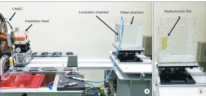
An electron-irradiation device was used for the electron- beam irradiations, as shown in Fig. 1. It consists of specially designed scattering foils and collimators to generate an optimal electron beam for FLASH preclinical studies. We do not discuss its detailed geometry in the present work be- cause the irradiation device is still under study.
The ionization chamber was calibrated in terms of water equivalents using a Co-60 reference beam. We applied the TRS-398 protocol to determine the dose in water [11]. The reference point of the ionization chamber was positioned at
zref=0.6R
50−0.1 cm, where R
50is the half-value depth in wa- ter [11]. In this work, we determined R
50by measuring the percentage depth dose (PDD) curve using a radiochromic film. The ionization measurements were performed at po- larization voltages of 400 V and 200 V for 100 electron-beam pulses at the repetition rate of 50 Hz using pulse-mode control of the pulse-modulator system [16]. We applied the values of k
scalculated with the new method to correct the measured charge, and we also applied environmental and polarity corrections according to the TRS-398 protocol [11].
Results
1. Calculation and verification
Fig. 2 shows f
1/f
2and 1/f
1calculated as a function of u
1for
V1/V
2=400/200 using equations (3) and (4) for the Advanced Markus
®chamber, a plane-parallel ionization chamber with an electrode spacing of 1 mm. The value of k
scan be determined as a function of M
1/M
2, because k
s=1/f
1and M
1/
M2=f
1/f
2.
In this manner, we calculated k
sfor the 22 selected data
a b
LINAC
Irradiation head
Lonization chamber Water phantom Radiochromic film
Fig. 1. Experimental setup (a) for reference dosimetry using an Advanced Markus® chamber and (b) for percentage depth dose measurements using a radiochromic film in water. LINAC, linear accelerator.
0.00 1.9 1.8 1.7 1.6 1.5 1.4 1.3 1.2 1.1 1.0
Calculatedvalue
u1
2.25 0.25 0.50 0.75 1.00 1.25 1.50 1.75 2.00
1/
/ f f f
1 1 2
Fig. 2. Ratio of the ion-collection efficiency (f1/f2) and the correction factor (1/f1) calculated as a function of u1 using Boag’s model.
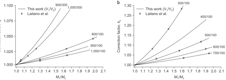
points, and the calculated results are shown in Fig. 3 to- gether with the results of Laitano et al. [7]. Here, Fig. 3a and Fig. 3b, respectively, are for cases with small and with large slopes of k
sas a function of M
1/M
2[7]. Comparing the cal- culated and published values of ks shows good agreement, i.e., to within 0.1%.
The calculated values of k
sfor the Advanced Markus chamber we used to measure the dosimetry of high-DPP electron beams is shown in Fig. 4. This figure shows the two k
scurves at two voltage ratios obtained with the new method (based on Boag’s model) and the two correspond- ing k
scurves calculated using current methods (those of the IAEA and the AAPM). The k
scurves obtained using the new method can be fitted with the following function for practi- cal use:
(5)
Here, b
0=1.3890, b
1=−0.9705, and b
2=0.5819 for polariza- tion voltage ratio V
1/V
2=400/200 and b
0=1.0413, b
1=−0.1549, and b
2=0.1157 for V
1/V
2=300/100. In Fig. 4, the values of k
sobtained with the currently used IAEA TRS-398 and AAPM TG-51 protocols are similar, but they are higher than those obtained with Boag’s model. Compared to the k
svalue for
M1/M
2=1.10 at V
1/V
2=400/200, the results from the IAEA TRS-398 and AAPM TG-51 protocols differed by about 8.9%
and 8.2%, respectively, although no significant difference was found in the range M
1/M
2<1.01.
2. Electron-beam measurements
The PDD curve measured with radiochromic film in wa- ter to determine the beam-quality index R
50(=2.4 g/cm
2) is shown in Fig. 5. The mean electron energy at the phantom surface, E–=2.33 R
50=5.6 MeV, and the most probable energy,
Ep=0.22+1.98 R
p+0.0025 R
p2≈ 6.4 MeV, can be determined from the PDD plot in Fig. 5, where R
p(=3.1 g/cm
2) is defined as the practical range of the electron beam in water [17].
These parameters are similar to those of a clinical electron beam with a nominal energy of 6 MeV [17].
We took into account the 0.2-cm-thick window made of
1.0 1.100
1.075
1.050
1.025
1.000 Correctionfactor,ks
M M1/ 2
2.1 This work (V /V )
Laitano et al.
1 2
1.1 1.2 1.3 1.4 1.5 1.6 1.7 1.8 1.9 2.0 900/300
1,000/300
800/100
1,000/100 900/100
1.0 1.30
1.25
1.20
1.15
1.10
1.05
1.00 Correctionfactor,ks
M M1/ 2
2.1 This work (V /V )
Laitano et al.
1 2
1.1 1.2 1.3 1.4 1.5 1.6 1.7 1.8 1.9 2.0 300/100
400/100
500/100
700/100 600/100
a b
Fig. 3. Comparison of the ion-recombination correction factors recalculated in this work with data published by Laitano et al. [7] for 5 polarizing voltage ratios. See text for the explanation of the difference between graphs (a) and (b).
1.000 1.100
1.075
1.050
1.025
1.000 Correctionfactor,ks
M M1/ 2
1.150 1.025 1.050 1.075 1.100 1.125 IAEA TRS-398
AAPM TG-51
V V V V
1/ 2=400/200 / =300/100
1 2
Boag's model (this work)
Fig. 4. The ion-recombination correction factors at V1/V2=400/200 and V1/V2=300/100 calculated in this work using Boag’s model.
The correction factors calculated by the conventional methods are included for comparison.
polymethyl methacrylate, with a density of 1.19 g/cm
3, in determining the measurement depth. The reference depth,
zref=1.38 g/cm
2, and the beam-quality factor as func- tions of R
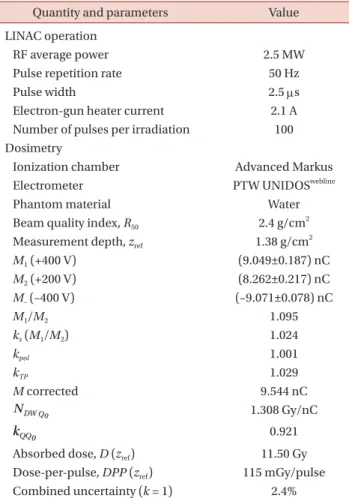
50were taken from the tabulated value for the Markus chamber in the TRS-398 protocol. The determined dose in water at the reference depth is listed in Table 1.
Because the measured dose D (z
ref) in the table is for 100 electron-beam pulses at a 50 Hz repetition rate, the aver- age dose rate is 5.75 Gy/s, and DPP (z
ref)=115 mGy/pulse.
The combined standard uncertainty in this measurement is estimated to be 2.4% (coverage factor k=1), which includes contributions from the measured value (0.1%), the ion- recombination correction factor (2.0%), a polarity correc- tion factor (0.4%), an air-density correction factor (0.2%), an ionization-chamber calibration factor (0.6%), a quality factor (1.0%), and others (0.5%). Here, we assumed the un- certainty in the ion-recombination correction factor to be the value given by Boag [6].
Discussion
In applying Boag’s model to calculate the ion-recombina- tion correction factor, we verified that the results calculated by our method are the same as those calculated by the it- erative numerical method. Our new method can be applied in practical applications without iterative calculations, and it can be presented in the form of the equation currently used in the TRS-398 protocol.
It is important to note that only the voltage ratio V
1/V
2is used in the TRS-398 and TG-51 protocols. However, to de- termine the correction factor, two voltages must be applied separately to use Boag’s model. This means, for example, that for the two voltage ratios V
1/V
2=400/200 and V
1/V
2=300/150, the same correction factor is calculated from the TRS-398 and TG-51 protocols, but the results are different in Boag’s model for M
1/M
2>1.3. In addition, the current method is independent of the type of ionization chamber, but Boag’s model requires the electrode spacing of the ionization chamber in order to calculate the electric field in the cavity [6]. In high-DPP (>200 mGy/pulse) or FLASH beams, higher values of M
1/M
2require additional verification. However, performing such additional verifications is currently diffi- cult due to the lack of reported data.
Although several forms of the relationship between high DPP and the ion-collection efficiency of the ioniza-
0.0 100
90 80 70 60 50 40 30 20 10 0
PDD(%)
Depth in water (g/cm )2
3.5 1.0
0.5 1.5 2.0 2.5 3.0
Zref
R50
Rp
Fig. 5. Measured percentage depth dose (PDD) curve used to determine the beam-quality index R50, including the reference depth zref and the practical range Rp.
Table 1. Summary of the LINAC operating parameters and electron-beam dosimetry results
Quantity and parameters Value
LINAC operation
RF average power 2.5 MW
Pulse repetition rate 50 Hz
Pulse width 2.5 μs
Electron-gun heater current 2.1 A Number of pulses per irradiation 100 Dosimetry
Ionization chamber Advanced Markus
Electrometer PTW UNIDOSwebline
Phantom material Water
Beam quality index, R50 2.4 g/cm2 Measurement depth, zref 1.38 g/cm2
M1 (+400 V) (9.049±0.187) nC
M2 (+200 V) (8.262±0.217) nC
M– (–400 V) (–9.071±0.078) nC
M1/M2 1.095
ks (M1/M2) 1.024
kpol 1.001
kTP 1.029
M corrected 9.544 nC
1.308 Gy/nC
0.921
Absorbed dose, D (zref) 11.50 Gy Dose-per-pulse, DPP (zref) 115 mGy/pulse Combined uncertainty (k = 1) 2.4%
LINAC, linear accelerator.
tion chambers used for absolute dosimetry were reported [5,8], applying these results directly to obtain dose deter- minations using an ionization chamber is difficult without performing absolute dosimetry. Film dosimetry may be exploited instead of absolute dosimetry for studying the ion-recombination correction factor for high-DPP beams, although the accuracy is limited. Further, since Boag’s the- ory has not been validated for high-DPP (>200 mGy/pulse) beams, in this study we performed the measurements only for a dose rate obtained at SSD=100 cm.
Conclusions
We carried out the present study in order to devise a practical method of applying Boag’s improved model for the dosimetry of high-dose-rate electron beams using com- mercial ionization chambers. This correction method can be applied to DPP ranges up to about 120 mGy/pulse. This upper limit is a suggested value based on the verification of Laitano et al. [7]. It can also be applied to electron beams of higher DPP, subject to independent verifications.
The estimated dose rate of electron beams used in this study is 11.50 Gy/s, assuming a LINAC pulse repetition rate of 100 Hz. This value is lower than that required in FLASH preclinical studies [2,3]. However, the dose rate can be increased significantly by reducing the SSD, as shown in a previous study using our LINAC system [16]. We plan to continue additional studies on the development of correc- tion methods for FLASH beams, eventually applying the results to the construction and commissioning of a FLASH electron-beam irradiation system.
Acknowledgements
The study was supported by the Dongnam Institute of Radiological and Medical Sciences (DIRAMS) grant funded by the Korea government (MSIT) (No. 50498-2020).
Conflicts of Interest
The authors have nothing to disclose.
Availability of Data and Materials
All relevant data are within the paper and its Supporting Information files.
Author Contributions
Conceptualization: Dong Hyeok Jeong. Data curation:
Dong Hyeok Jeong, Kyoung Won Jang. Formal analysis:
Heuijin Lim, Sang Koo Kang. Methodology: Dong Hyeok Jeong. Project administration: Dong Hyeok Jeong. Software:
Manwoo Lee. Validation: Dong Hyeok Jeong, Kyoung Won Jang. Visualization: Dong Hyeok Jeong, Kyoung Won Jang.
Writing–original draft: Dong Hyeok Jeong, Kyoung Won Jang. Writing–review & editing: Dong Hyeok Jeong, Kyoung Won Jang.
References
1. Pimpinella M, Andreoli S, De Angelis C, Della Monaca S, D’Arienzo M, Menegotti L. Output factor measurement in high dose-per-pulse IORT electron beams. Phys Med. 2019;
61:94-102.
2. Montay-Gruel P, Petersson K, Jaccard M, Boivin G, Ger- mond JF, Petit B, et al. Irradiation in a flash: unique sparing of memory in mice after whole brain irradiation with dose rates above 100Gy/s. Radiother Oncol. 2017;124:365-369.
3. Schüler E, Trovati S, King G, Lartey F, Rafat M, Villegas M, et al. Experimental platform for ultra-high dose rate FLASH irradiation of small animals using a clinical linear accelerator. Int J Radiat Oncol Biol Phys. 2017;97:195-203.
4. Nisbet A, Thwaites DI. Polarity and ion recombination cor- rection factors for ionization chambers employed in elec- tron beam dosimetry. Phys Med Biol. 1998;43:435-443.
5. McManus M, Romano F, Lee ND, Farabolini W, Gilardi A, Royle G, et al. The challenge of ionisation chamber dosim- etry in ultra-short pulsed high dose-rate Very High Energy Electron beams. Sci Rep. 2020;10:9089.
6. Boag JW, Hochhäuser E, Balk OA. The effect of free-elec- tron collection on the recombination correction to ioniza- tion measurements of pulsed radiation. Phys Med Biol.
1996;41:885-897.
7. Laitano RF, Guerra AS, Pimpinella M, Caporali C, Petrucci
A. Charge collection efficiency in ionization chambers exposed to electron beams with high dose per pulse. Phys Med Biol. 2006;51:6419-6436.
8. Petersson K, Jaccard M, Germond JF, Buchillier T, Bochud F, Bourhis J, et al. High dose-per-pulse electron beam dosim- etry - a model to correct for the ion recombination in the Advanced Markus ionization chamber. Med Phys. 2017;44:
1157-1167.
9. Pearce JAD. Characterisation of two new ionisation cham- ber types for use in reference electron dosimetry in the UK. Teddington: National Physical Laboratory. 2004; NPL Report DQL-RD001.
10. Gotz M. Dosimetry of highly pulsed radiation fields.
Dresden: Helmholtz-Zentrum Dresden-Rossendorf. 2018;
HZDR-090.
11. International Atomic Energy Agency. Absorbed dose deter- mination in external beam radiotherapy: an international code of practice for dosimetry based on standards of ab- sorbed dose to water. Vienna: International Atomic Energy Agency. 2006; IAEA TRS-398.
12. Almond PR, Biggs PJ, Coursey BM, Hanson WF, Huq MS, Nath R, et al. AAPM’s TG-51 protocol for clinical reference dosimetry of high-energy photon and electron beams. Med
Phys. 1999;26:1847-1870.
13. Kry SF, Popple R, Molineu A, Followill DS. Ion recombina- tion correction factors (P(ion)) for Varian TrueBeam high- dose-rate therapy beams. J Appl Clin Med Phys. 2012;13:
318-325.
14. Lim H, Jo W, Lee DE, Lee M, Kim SH, Shin SW, et al. Status of the DIRAMS C-band standing-wave accelerator for a radiotherapy machine. Paper presented at: 9th Asia Forum for Accelerators and Detectors; 2018 Jan 28-31; Daejeon, Korea. p. 38.
15. Lim H, Lee M, Kim MY, Yi J, Lee M, Kang SK, et al. Mea- surement of energy parameters for electron gun heater currents and output dose rate for electron beams from a prototype linac. Prog Med Phys. 2016;27:25-30.
16. Jang KW, Lee M, Lim H, Kang SK, Lee SJ, Kim JK, et al.
Development of a wide dose-rate range electron beam irra- diation system for pre-clinical studies and multi-purpose applications using a research linear accelerator. Prog Med Phys. 2020;31:9-19.
17. Ding GX, Rogers DW. Mean energy, energy-range relation- ships and depth-scaling factors for clinical electron beams.
Med Phys. 1996;23:361-376.