1. INTRODUCTION
As the cumulative amount of the spent fuel increases, the reliable and effective management of spent fuel becomes a worldwide mission. A considerable R&D effort is being made to develop a management technology that will enhance environmental friendliness and proliferation resistance as well as maximize the use of available energy resources. With such a background, the Korea Atomic Energy Research Institute (KAERI) is developing the Advanced Spent Fuel Conditioning Process (ACP) as a pre-disposal treatment process for spent fuel [1]. The ACP equipment must be remotely operated and maintained by manipulators in an intense radiation field (hot cell). Several mechanical Master-Slave Manipulators (MSMs) are installed in the ACP hot cell. However, there are disadvantages to this type of manipulator. Since the master and the slave are directly connected, the operator is required to remain in close proximity of the working environment, and the volumetric coverage of the slave manipulators is limited because the system must be mounted on the hot cell wall. Also, the ratio of slave to master forces is fixed at about 1:1, so the slave can apply forces only within the range of human capabilities.
In this regard, the servo-manipulator mounted on an overhead bridge is additionally required for the operation and maintenance of all the ACP equipment. It can overcome the limitation of access and the ratio of slave to master forces that are drawbacks of MSMs, so the Bridge Transported Bilateral Force-Reflecting Servo-Manipulator (BTSM) system is being developed for remotely operating and maintaining the ACP equipment in a radioactive environment at KAERI. The BTSM system consists of four components: a transporter with a telescoping tubeset, a slave manipulator, a master manipulator, and a remote control system. The system has no direct mechanical links between the operator control room and the remote (slave) manipulator. The main operation inside the hot cell will be using the wall-mounted MSMs at the shielded window workstations using direct viewing. The bilateral force-reflecting servo-manipulator will be used for hard to reach areas of the hot cell using the MSMs. Work using the servo-manipulator is accomplished with the overhead bridge with the aid of remote viewing capability. The BTSM system is remotely operated using the remote control system and the
wall-mounted master manipulator from the uncontaminated side of the hot cell (operation area).
The first version of the BTSM system as prototype 1 was manufactured in 2002 and was tested in 2003 [2-3]. During the performance test, several items have been modified. The second version of the BTSM system as prototype 2 was manufactured in 2004, and is currently under the performance test. The prototype 2 will be installed at the ACP hot cell on June 2005 after the accomplishment of the performance test. The prototype 2 will be used for the process equipment operation and maintenance during the demonstration of the ACP.
This paper describes the BTSM system of the prototype 2, which has been designed and manufactured for duties in MSMs’s inaccessible areas under remote control conditions. The BTSM system provides capabilities similar to standard through-the-wall MSMs systems. But, this system will highly increase the volume of coverage for the operation and maintenance of the ACP equipment.
2. DESIGN REQUIREMENTS
2.1 Cell configurationThe primary ACP hot cell dimensions are 11m (L) x 2m (W) x 4.3m (H). The hot cell is segmented into a maintenance cell and a process cell. The maintenance cell is a room for hands-on maintenance of the bridge crane and the BTSM system. The process cell is a room for operation of the process equipment. The former has low radiation levels and the latter has high radiation levels. The bridge crane and the BTSM system travel along the length of the hot cell. The gate crane prevents persons from the radiation exposure for hands-on maintenance of the bridge crane and the BTSM system in the maintenance cell. Due to space limitation, the gate crane, the bridge crane, and the BTSM system operate on the same runway.
2.2 Environmental conditions
Environmental conditions for the ACP hot cell for the development of the BTSM system are listed in Table 1. The ACP equipment will operate at the hot cell. Therefore, the BTSM system will be subjected to the environmental conditions of the hot cell.
A Bridge Transported Bilateral Force-Reflecting Servo-Manipulator for
Maintenance of Nuclear Pyroprocessing Equipment
B.S. Park
*, J.H. Jin
*, B.S. Ko
*, J.K. Lee
*, and J.S. Yoon
** Korea Atomic Energy Research Institute, Dukjin-dong, Yuseong-gu, Daejeon, Korea (Tel : +82-42-868-2596; E-mail : [email protected])
Abstract: The Advanced Spent Fuel Conditioning Process (ACP), which is a pre-disposal treatment process for spent fuel is being developed at the Korea Atomic Energy Research Institute (KAERI). The ACP equipment is operated in an intense radiation field as well as in a high temperature. Thus, the equipment is designed in consideration of the remote handling and maintenance. This paper describes a Bridge Transported Bilateral Force-Reflecting Servo-Manipulator (BTSM) system, which is being developed to overcome the limitation of access that is a drawback of the mechanical Master-Slave Manipulators (MSMs), which are mounted on the ACP hot cell wall for the operation and the maintenance of the ACP equipment. The BTSM system was manufactured and temporally installed at the mockup to test its performance. The manufactured BTSM system will be installed at the ACP hot cell on June 2005 after the accomplishment of the performance test. The BTSM system consists of four components: a transporter with a telescoping tubeset, a slave manipulator, a master manipulator, and a remote control system. This system will highly increase the volume of coverage for the operation and maintenance of the ACP equipment.
Keywords: Advanced Spent Fuel Conditioning Process (ACP), Hot cell, Transporter, Force-Reflecting, Servo-Manipulator, Telescoping tubeset, Operation and maintenance
Table 1 Environmental conditions. Item Conditions Cell type α-γ Atmosphere Air Temperature 25 ~ 35oC Pressure -27 ~ -30 mmAq γ-radiation (total dose) ~ 4 Gy/h (4 x 10⁴ Gy) 2.3 BTSM system requirements
The bridge, trolley, and telescoping tubeset are needed to horizontally, laterally, and vertically position the slave manipulator inside the hot cell. As a consideration for the failure of their motors, they should be manually driven from the process cell to the maintenance cell. Also, their motors should be continuously controlled with travel speeds of less than 100 mm/sec. Considering the distance of 2.47m between the bridge rail and the working table of the hot cell, the maximum height, 1.2m, of the ACP equipment on the working table, and the height of the slave manipulator to be designed, the length of the fully retracted/extracted telescoping tubeset should be determined. The telescoping tubeset should have a handling capacity of more than 150 kgf. The interface system is needed to remotely detach the slave manipulator from the tubeset for maintenance using MSM. The motor parts of the slave manipulator should be designed in modules for ease of maintainability. The modules should be designed to be remotely removable from the body of the slave manipulator using the MSMs and cranes. The reach of the manipulators and the velocity of the end-effector tip should be less than 1 m and more than 1 m/sec, respectively. The continuous load capacity and the weight of the slave manipulator should be more than 10 kgf and less than 50 kgf, respectively. Considering the space constraint of the ACP hot cell, the BTSM system inside the cell should be compact and the location of cameras that provide the viewing capability for the cell should be optimally determined. The BTSM system inside the cell should withstand a total absorbed radiation dose of 108 rad. The control of the BTSM inside the cell should be achieved using the master manipulator with force reflection and a manual console.
3. DESIGNS AND MANUFACTURE OF THE
BTSM SYSTEM
3.1 Overview of the BTSM system
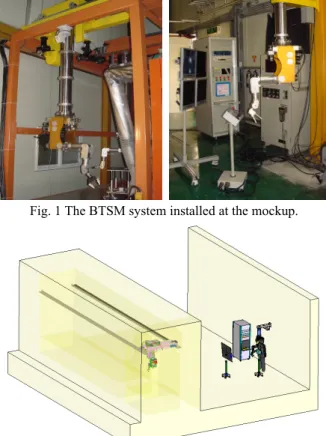
The BTSM system has been designed for duties in MSMs’s inaccessible areas under remote control conditions using Solid Edge, which is 3D CAD software. Fig. 1 shows the manufactured BTSM system. It was temporarily installed to test its performance in the mockup, which is equipped with MSM and crane to simulate the hot cell dimensional envelope and operations. Fig. 2 shows the layout of the ACP hot cell, which is under construction. The manufactured BTSM system will be installed at the ACP hot cell on June 2005 after the accomplishment of the performance test. The BTSM system consists of four components: a transporter, a slave manipulator, a master manipulator, and a remote control system. The transporter, which consists of the bridge, the trolley, and the telescoping tubeset with an interface system, is located at a hot cell to position the slave manipulator. The slave manipulator is mounted on the telescoping tubeset via the interface system. The master manipulator is mounted on the telescoping tubeset attached to a fixed support on the wall of the operation area
outside the hot cell. The manipulator control system consists of a control cabinet, manual console, and LCD monitors. This system is located around the master manipulator. The master manipulator and the slave manipulator, which is a single arm system, are kinematically similar, except for the handle and the tong. The manipulators have 6 degrees of freedom (DOF) plus the end-effectors (handle and tong) motion. The designed manipulator is a force-reflecting servo-manipulator. To provide a bilateral-positioning control with force feedback, seven axes of the manipulators are driven by electrical servomotors. As a bilateral-positioning control with force feedback without sensor technology, the BTSM system will offer tactile feedback. The operator will get feedback concerning the forces, which have occurred from the slave manipulator via the master manipulator. This force reflection enables the operator not only to watch but also to feel his work. With this, even complicated operations can be carried out, without the risk of damaging or destroying tools or objects. LCD monitors are provided to provide visual feedback to the operator. Remote radiation tolerant cameras send pictures of the working environment to camera monitors for the operator to view.
Fig. 1 The BTSM system installed at the mockup.
Fig. 2 Graphical view of the BTSM system in ACP hot cell. 3.2 Transporter
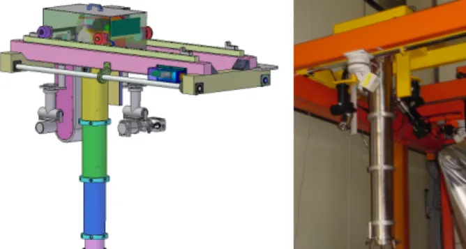
Fig. 3 shows the transporter, which horizontally, laterally, and vertically positions the slave manipulator. The moving distance and speed are shown in Table 2. The transporter is composed of four subassemblies: a bridge, a trolley, a telescoping tubeset, and an interface system. The bridge is composed of two girders equipped with rail. Two saddles with two rollers, respectively, support the bridge. A shaft connects two of the four rollers, which are driving rollers. The drive module is mounted on this shaft. The distance between the
centers of the two saddles is 1.8 m, and the length of the saddle is 0.78 m. Two radiation tolerant cameras (ROS SCE-X-25) with a total radiation absorbed dose of 5 x 10⁴ rad are mounted on the girder and the trolley based on the space considerations and viewing angles. The camera attached to trolley is equipped with a 3D lens. The trolley is composed of a box supported by four rollers. Two shafts connect the four rollers. The drive module is mounted on one shaft. The size of the trolley box is 372 mm x 670 mm x 275 mm. The telescoping tubeset is composed of four tubes: one fixed tube and three moving tubes. The telescoping tubeset is vertically mounted on the bottom of the trolley box. The drive module is also mounted on the floor of the trolley box. The tubeset is pulled by a chain, which is driven by a sprocket. The lifting motion of the tubeset is in three steps with a travel of 1100 mm. The height of the fully retracted and the fully extracted tubeset without the slave manipulator is 630 mm and 1730 mm, respectively. The distance between the fully extracted tubeset bottom and the working table top of the hot cell is 955 mm. The tubeset has a capacity of 200 kg. 12 rollers guide each tube such that the telescoping tubeset can be vertically moved with hardly any play without the rotation of the tubeset. Two-power cables and two-signal cables with a diameter of 11.6 mm, respectively, are simultaneously pushed into or pulled out the cable storage box along with a telescoping tubeset motion. The tubeset accommodates internally four cables to transmit the electric supply to the slave manipulator. The drive modules for motions of the girder and the trolley consist of an electrical motor, brake, and clutch, respectively. The drive module for motion of the telescoping tubeset consists of an electrical motor, brake, clutch, sprocket, reverse clutch, mechanical ratchet, and a manual handle. Fig. 4 shows the drive module for the telescoping tubeset motion. At motor failed conditions, the operator rotates the manual handle using MSM to drive the sprocket. The interface system remotely can attach and detach the slave manipulator from the tubeset using MSM. This system consists of two parts: an upper part and a lower part. The upper part is composed of the rotation plate and the fixed plate with three-support pins. The lower part is equipped with three-guide pins. The upper part is mounted on the telescoping tubeset, and the lower part is mounted on the slave manipulator. At the attachment of the slave manipulator, the support pins mounted on the lower part and the guide pins mounted on the upper part are first sequentially inserted into the hole of the upper part and the lower part, respectively, by pulling up the lower part. Second, the rotation plate of the upper part is rotated using MSM and is locked by a handle. The detachment of the slave manipulator is performed in reverse of the attachment. The interface system accommodates 4 radiation tolerant electrical connectors (LEMO FGG/EGG 4B, non-latching) between the upper part and the lower part.
Fig. 3 A transporter positioning the slave manipulator.
Table 2. Technical characteristics for transporter Traverse Hoist 1400 ~ 62 1100 ~ 63 200 Travel Distance (mm) Speed (mm/sec) Load capacity (kgf) 8300 ~ 62
Fig. 4 A drive module for the telescoping tubeset motion. 3.3 Bilateral force-reflecting servo-manipulator
Servo-manipulators can be driven with electric motors or hydraulic actuators. Hydraulic actuators are most favorably applied in underwater or extremely heavy-duty applications. Electromechanical drive systems offer 1% of peak load force sensitivity through backdrivable gear trains and are used in most modern servo-manipulator systems. As an object in space has 6 DOF, a general-purpose manipulator must have at least 6 DOF plus an end-effector actuation. Additional DOFs are rarely used in serv-omanipulator systems as they are redundant, increase the system complexity, are difficult to operate, and are only rarely useful. Modern servo-manipulators usually have a configuration similar to the human arm [4-8]. The joints are almost always rotary. Prismatic joints, though common in robots and MSMs, are rarely used in servo-manipulators. The general-purpose two-fingered tong gripper is the most used end-effector in servo-manipulators.
On the basis of this, as shown in Fig. 5, we have designed and manufactured a bilateral force-reflecting servo-manipulator with the elbow-up stance. The master manipulator is a replica of the slave manipulator. The drive mechanism of the slave manipulator is basically identical with that of the master manipulator, except for the gripper and the handle, respectively. The manipulators have 6 DOF plus a parallel jaw motion and a handle motion, respectively. All the motors, measuring sensors, and the transmission gears of the manipulator are located in the body of the manipulator. The drive modules are equipped with planetary gearbox and three-phase servomotors, brakes, and resolvers on the motor shafts. Most drive modules of the manipulators are located behind their body except for the body joint. The drive modules are remotely changeable from the body of the slave manipulator using the MSMs and crane. There are no electrical cables from the slave body and the master body to the gripper and the handle, respectively. The radiation tolerant electrical connectors of the push-pull type (LEMO FIG/PKG 2B), which are amenable to handle by MSM, are accommodated for the electrical cable connection between the body and the drive modules. The drive module electrical cables are connected to the lower part connectors of the interface system via the inside of the body. The body motion is driven via a concentric shaft of a drive module and the spur gear. The transmission of the motion from the upper arm motor and the lower arm motor to their joints is realized via shafts of drive modules, bevel gears, and a connecting rod for
the lower arm joint. The transmission of the motion from a lower arm twist motor, two wrist motors, a gripper motor, and a handle to their joints is realized via shafts of drive modules, bevel gears, and stainless steel wires [9-10]. Potentiometers for measuring the absolute position of all the axes are mounted on the shaft of the second bevel gear for the arm joints and the spur gear for the body joint. There is no direct connection between the joints and motors. The length of the upper arm and the lower arm for the manipulators are 330 mm, and the length of the gripper is 255 mm. The body dimension is 281 mm x 218 mm x 485 mm. Table 3 shows the technical characteristics for servo-manipulator. The weights of the slave manipulator and the master manipulator are about 50 kg and 40 kgf, respectively. The continuous load capacity of the slave manipulator is 15 kgf. The slave body hook, which can be remotely changeable from the body, has a lifting capacity of 30 kgf. The slave manipulator is mounted on the telescoping tubeset via an interface system. The master manipulator system is composed of three parts: a bridge of the cantilever type, a telescoping tubeset attached to the bridge, and a master manipulator attached to the telescoping tubeset. The tubeset can be manually extracted or retracted by an operator with a travel of 300 mm. Because the height of the operators is different, the tubeset motion is useful for adjusting the distance between the floor and the bottom of the master arm handgrip in a nominal stance.
(a) slave manipulator (b) master manipulator Fig. 5 Bilateral force-reflecting servo-manipulator. Table 3. Technical characteristics for servo-manpulator
Items Value Weight (slave/master) Load capacity – continuous Resistance to radiation Gripping force Lifting capacity Reach 50 kgf / 40 kgf 15 kgf 106Gy 30 kgf 30 kgf 836 mm
Motor type AC servo motor with resolver Motion Range Body rotation Shoulder Elbow Azimuth (Yaw) Wrist elevation Wrist rotation -267o~ +87o -45o~ +45o -45o~ +45o -180o~ +180o -135o~ +45o -180o~ +180o Gripper opening 0 mm ~ 70 mm
3.4 Remote control system
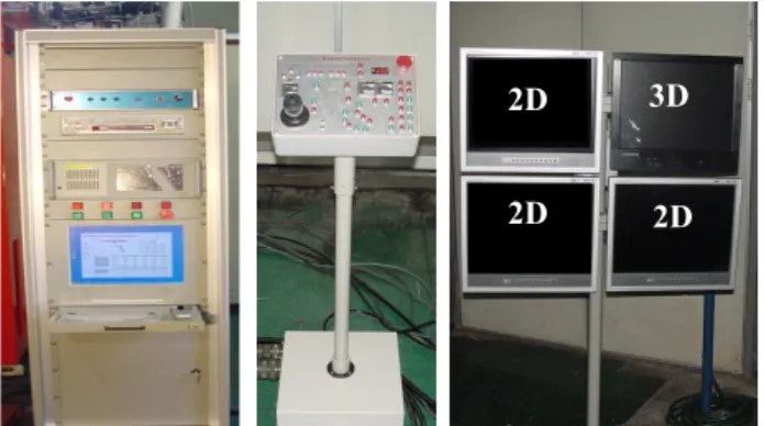
As shown in Fig. 6, the remote control system is composed of a movable control cabinet, control console, and camera monitors. The control cabinet involves motor drives, PC, video recorder, camera controller, and so on. The PC control system is accomplished based on the PCI bus and Windows operating system. Multi-axis Motion Controllers (MMCs) made by SAMSUNG controls the BTSM system. Fig. 7 shows the BTSM system software, which has been written in Borland C++ Builder 6.0 under Windows 2000. The manual console is used to move the slave manipulator and/or the transporter without operating the master manipulator. The manual console includes a joystick and a set of control switches and buttons. The joystick controls the traveling, traverse, and hoisting motion of the transporter. Buttons and switches independently control the joints of the slave manipulator, select the camera, and control the pan/tilt/zoom/focus of the selected camera. As the operator moves the master manipulator, the slave manipulator follows the motions of the master manipulator in real time. 2D and 3D cameras send pictures of the working environment back to the camera monitors for the operator to view.
(a) control cabinet (b) manual console (c) camera monitors Fig. 6 The remote control system of the BTSM system.
Fig. 7 The operation software of the BTSM system.
4. CONCLUSIONS
A Bridge Transported Bilateral Force-Reflecting Servo-Manipulator (BTSM) system to remotely operate and maintain the Advanced spent fuel Conditioning Process (ACP) equipments in a radioactive environment has been developed. The BTSM system is composed of four components: a slave manipulator, a transporter positioning the slave manipulator, a master manipulator, and a remote control system with a
3D
2D
control cabinet and manual console. The master manipulator and the slave manipulator are kinematically similar, except for the handle and the tong, respectively. The manipulators have 6 degrees of freedom plus the jaws motion. To provide a bilateral-positioning control with force feedback, seven axes of the manipulators are driven by electrical servomotors. The developed manipulator is a smaller size compared with that of the existing replica type of master-slave servo-manipulators. And the slave manipulator has a bigger handling capacity, 15 kgf, compared with the size of the existing slave manipulators. The slave manipulator can be remotely detached from the telescoping tubeset of the transporter using MSMs, and the drive modules can also be detached from the manipulator body using MSMs and crane.
The manufactured BTSM system was temporally installed at the mockup cell to test its performance. This system will be installed at the ACP hot cell on June 2005 after the accomplishment of the performance test.
ACKNOWLEDGMENTS
This research has been carried out as a part of the nuclear R&D program funded by the Ministry of Science and Technology in Korea.
REFERENCES
[1] G. You, et al., “Development of hot cell facilities for demonstration of ACP,” Proceedings of the 4th Korea-China Joint Workshop on Nuclear Waste Management, pp. 191-204, 2003.
[2] B. S. Park, J. H. Jin, S. H. Ahn, T. G. Song, D. G. Kim, and J. S. Yoon, “Design of a Bridge Transported ServoManipulator System for a Radioactive Environment,” Proceedings of the ICCAS 2003, 2003. [3] B. Park, et al., “Transmission Characteristics of a
Wire-Driven Bridge Transported Servo Manipulator Prototype for the ACP Maintenance,” Proceedings of the Korean Radioactive Waste Society Spring 2004, pp. 306-315, 2004.
[4] J. N. Herndon, H. L. Martin, and P. E. Satterlee, Jr., “The State-Of-The-Art Model M-2 Maintenance System,” Proc. of the 1984 National Topical Meeting on Robotics and Remote Handling in Hostile Environments, pp. 147-154, 1984.
[5] D. P. Kuban and H. L. Martin, “An Advanced Remotely Maintenable Force-Reflecting Servomanipulator Concept,” Proc. of the 1984 National Topical Meeting on Robotics and Remote Handling in Hostile Environments, pp. 407-415, 1984.
[6] Colombi, T. Raimondi, and G. Costi, "Improvement of Transparency of Bilateral Master-Slave Force Reflecting Servomanipulators," Proceedings of the ANS 5th Topical Meeting on Robotics and Remote Systems, pp. 935-941, 1993.
[7] S. Kawatsuma, et al., “The status of two-arm bilateral servomanipulators system development,” Proceedings of Remote Systems and Robotics in Hostile Environments, pp. 630-637, 1987.
[8] P. Fischer, R. Daniel, and K. Siva, “Specification and design of input devices for teleoperation,” Proceedings of IEEE International Conference on Robotics and Automation, pp. 540-545, 1990.
[9] H. Shigeo, "Coupled Tendon-Driven Multijoint Manipulator" Proceedings of the 1991 IEEE Int. Conf. Robotics and Automation, pp. 1268-1278, 1991.
[10] Eugene I. Rivine, Mechanical Design of Robots, McGraw-Hill Book Company, 1988.