Optical Encryption Scheme for Cipher Feedback Block Mode
Using Two-step Phase-shifting Interferometry
Seok Hee Jeon1 and Sang Keun Gil2**
1Department of Electronic Engineering, Incheon National University, Incheon 22012, Korea
2Department of Electronic Engineering, The University of Suwon, Hwaseong, Suwon 18323, Korea
(Received December 31, 2020 : revised March 2, 2021 : accepted March 6, 2021)
We propose a novel optical encryption scheme for cipher-feedback-block (CFB) mode, capable of encrypting two-dimensional (2D) page data with the use of two-step phase-shifting digital interferom-etry utilizing orthogonal polarization, in which the CFB algorithm is modified into an optical method to enhance security. The encryption is performed in the Fourier domain to record interferograms on charge-coupled devices (CCD)s with 256 quantized gray levels. A page of plaintext is encrypted into digital interferograms of ciphertexts, which are transmitted over a digital information network and then can be decrypted by digital computation according to the given CFB algorithm. The encryption key used in the decryption procedure and the plaintext are reconstructed by dual phase-shifting interferometry, providing high security in the cryptosystem. Also, each plaintext is sequentially encrypted using differ-ent encryption keys. The random-phase mask attached to the plaintext provides resistance against pos-sible attacks. The feasibility and reliability of the proposed CFB method are verified and analyzed with numerical simulations.
Keywords : CFB mode, Digital holography, Optical encryption, Phase-shifting interferometry,
Symmetric block encryption
OCIS codes : (060.4785) Optical security and encryption; (070.1170) Analog optical signal processing;
(070.4560) Data processing by optical means; (090.1995) Digital holography; (090.2880) Holographic interferometry
*Corresponding author: [email protected], ORCID 0000-0002-3828-0939 Color versions of one or more of the figures in this paper are available online.
This is an Open Access article distributed under the terms of the Creative Commons Attribution Non-Commercial License (http://creativecommons. org/licenses/by-nc/4.0/) which permits unrestricted non-commercial use, distribution, and reproduction in any medium, provided the original work is properly cited.
Copyright © 2021 Current Optics and Photonics
I. INTRODUCTION
Information security has increasingly become an im-portant issue in many information societies. Compared to conventional electronic data-security methods, optical data security provides much freedom to encrypt data using the amplitude, phase, polarization, or wavelength of light. Since Refregier and Javidi firstly reported the optical en-cryption method of double random-phase encoding (DRPE) [1], lots of researchers have investigated optical encryption methods in information-security applications, because of their high-speed and parallel processing potential. In 2009, Matoba et al. reviewed various optical techniques in in-formation security, encryption, and authentication [2], and
Alfalou and Brosseau reviewed much work about optical image compression and encryption methods [3]. In 2014, Chen et al. presented a review of optical technologies for information-security systems, and analyzed the advantages and disadvantages of each optical security system [4]. Also, Javidi et al. presented an article about a roadmap for optical security, as an overview of the recent advances and chal-lenges of optical encryption techniques using free-space optics [5]. Among these optical encryption methods, digital holography is a useful technique in which fully complex data may be recorded and reconstructed digitally to realize optical encryption [6]. A method for more efficient direct recording of holographic information is phase-shifting in-terferometry, which uses a charge-coupled device (CCD)
- 155 -Current Optics and Photonics
to record the fully complex information. Some methods to use phase-shifting interferometry in an optical encryption system have been proposed [7–9]. Generally, as the number of phase-shift steps increases in phase-shifting interferom-etry, the reconstruction error in the acquisition of the fully complex information decreases. However, the multistep phase shift increases the amount of data being encrypted, so that much time might be required to transmit the secure information, and then the limitation of system errors is dominated by the resolution of the commercially available CCD. Especially, some researchers have proposed optical encryption systems using two-step phase-shifting interfer-ometry [10–14]. On the other hand, several optical encryp-tion methods based on polarizaencryp-tion have been considered for security [15–20]. As to the DRPE method, Naughton et al. introduced the concept of secure modes for conventional block-encryption systems and applied these concepts to DRPE optical encryption [21]. Recently, we proposed the optical encryption method of cipher-block-chaining (CBC) mode, using phase-shifting digital interferometry based on orthogonal polarization [22].
In this paper, we propose an optical encryption scheme for cipher-feedback-block (CFB) mode by means of two-step phase-shifting interferometry and orthogonal polariza-tion. Fourier-domain optical encryption is obtained by the interference of two waves in a phase-shifting interferometer of the Mach-Zehnder architecture. The interferometer con-sists of binary input data attached to a random-phase mask in the object beam, and a randomly distributed phase pat-tern with an encryption key in the reference beam, with the resulting interferograms being recorded on CCDs. The en-cryption key used in the deen-cryption process is also achieved by phase-shifting interferometry. Ciphertexts of the digital interferograms are transmitted over an information network and can easily be decrypted by digital computation. In Section II the CFB mode is briefly reviewed and the pro-posed optical encryption method for the CFB algorithm is explained, and in Section III the feasibility of the proposed method is verified by the results of numerical simulations and security analysis. Conclusions are summarized in Sec-tion IV.
II. CFB ENCRYPTION MODE AND THE PROPOSED METHOD
In the conventional cryptographic encryption of digital data, called a block, there are four standard modes: Elec-tronic Codebook (ECB), CBC, CFB and Output Feedback (OFB) in the data-encryption standard (DES) protocol. Among these block-encryption modes, CFB mode intro-duces a feedback operation into the cryptographic process. In this mode, the previous ciphertext block is fed back and used to encrypt the subsequent plaintext block. Figure 1(a) shows the algorithm for CFB mode encryption, and the en-cryption procedure is described as follows:
IV = C0, (1)
Oi = E(Ci–1) for 1 ≤ i ≤ n, (2) Ci = Pi⊕ Oi for 1 ≤ i ≤ n, (3) Pi = Ci⊕ D(Ci–1) = Ci⊕ Oi for 1 ≤ i ≤ n, (4) where IV denotes an initialization vector, Ci-1 denotes the previous ciphertext, Oi denotes the ith corresponding ci-pher by an encryption key K, Pi denotes the ith plaintext, Ci denotes the corresponding ith ciphertext, and n is the total
number of plaintext blocks being encrypted. E(∙) represents an encryption operation and D(∙) represents the correspond-ing decryption operation. An initialization vector IV is used as the first ciphertext block C0, which need not be secret
and should be sent to the receiver for decryption. However, this method is insufficient to maintain security strength because of the short length of the key, and is vulnerable to cryptoanalysis attacks.
Recently, electronic digital cryptographic algorithms have been analyzed by applying optical encryption tech-niques in which the ciphertext is no longer in digital infor-mation, but rather is in an analog random pattern, such as white noise. Inherently, an optical system carries out fast parallel processing with 2D array data, so it can have a very large key space, thereby enhancing security strength. In FIG. 1. Block diagrams for encryption. (a) Conventional CFB mode, (b) proposed CFB method.
Optical Encryption Scheme for Cipher Feedback Block... - Seok Hee Jeon and Sang Keun Gil 157 this paper, the concept of the CFB-mode algorithm is
modi-fied to propose an optical encryption scheme using phase-shifting interferometry. Figure 1(b) shows the proposed CFB method, and the encryption procedure is described as follows:
IV = C0, (5)
Oi = E(Ci–1) for 1 ≤ i ≤ n, (6) Ci = E(Pi, Ci-1) for 1 ≤ i ≤ n, (7) Pi = D(Ci, D(Oi)) for 1 ≤ i ≤ n, (8) where IV denotes an initialization p × q matrix, Ci–1 de-notes the previous ciphertext, Oi denotes the corresponding interferograms by the ith encryption key K
i, Ci denotes the corresponding ith ciphertext of the interferogram, and n is
the total number of plaintext pages being encrypted. E(∙) represents a digital holographic encryption operation, and D(∙) represents the corresponding holographic decryption operation. A page of plaintext is encrypted to ciphertexts by performing orthogonal-polarization-based two-step phase-shifting interferometry with the previous ciphertext. Inter-ferograms Oi and Ci are transmitted to the receiver and used to reconstruct the plaintext Pi by the corresponding decryp-tion process.
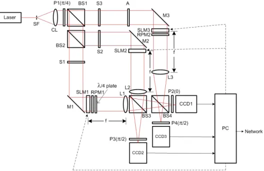
The optical architecture for two-step phase-shifting digi-tal holography using orthogonal polarization [20] can also be used for the proposed CFB encryption method. Figure 2 schematically shows the proposed optical encryption archi-tecture, which contains dual Mach-Zehnder interferometers. The collimated laser beam passes through a linear polarizer P1, the polarization direction of which is 45° with respect
to the horizontal axis, and is divided by beam splitters into two linear-polarized plane waves traveling in different paths. When shutters S1 and S2 are open and S3 is closed, the inner interferometer is operated to encrypt a previous ciphertext Ci-1 by a holographic encryption key Ki, which is intended to be made from the same previous ciphertext Ci-1. A previous ciphertext to be encrypted is displayed on an amplitude-type spatial light modulator SLM1 multi-plied by a random-phase mask RPM1 in the object-beam path, while a phase-type SLM2 displays the holographic encryption key in the reference-beam path. The object and reference wave functions in the inner interferometer are ex-pressed as si(x,y) = Ci–1(x,y)ejθ1(x,y) and ti(x,y) = ejKi(x,y), where exp[jθ1(x, y)] is a random-phase-mask function. Note that
an initialization-matrix value IV = C0(x, y) is used in the
first-stage encryption procedure, where C0 is assumed to be
a randomly generated 2D matrix pattern. The complex dis-tributions of the object and reference waves in the spatial-frequency plane, expressed as Si(α, β) = FT{si(x, y)} and Ti(α, β) = FT{ti(x, y)}, where FT represents the Fourier transform, are interfered onto two CCD1 and CCD2 by use of the Fourier-transform lenses L1 and L2. If the fast axis of a λ/4 plate is set along the vertical axis, then no phase shift occurs on CCD1 where the polarization direction of output analyzer P2 is aligned along the s-polarization axis, and a phase shift of π/2 radians occurs on CCD2 where the polarization direction of output analyzer P3 is aligned along the p-polarization axis. This two-step phase-shifting inter-ferometry gives two interference intensities as
������(�� �� 0) = |��(�� �)|�+ |��(�� �)|�+ 2|��(�� �)||��(�� �)| ���∆��, (9) ��������� ����� = |��(�� �)|�+ |��(�� �)|�+ 2|��(�� �)||��(�� �)| cos (∆��−��), (10) �������(�� �� 0) = |��(�� �)|�+ |��(�� �)|�+ 2|��(�� �)||��(�� �)| ���∆��, (11) ���������� ����� = |��(�� �)|�+ |��(�� �)|�+ 2|��(�� �)||��(�� �)| cos (∆��−��), (12) ∆��=�−�= ����������������������(�����) �������(�����)�(�����)�, (13) ���= |��||��| =�������������� ����� − (��+ ��)� � + ��������(�� �� 0) − (��+ ��)��. (14) ∆��=�−�= ���������������������(�����) ������(�����)�(�����)�, (15) ���= |��||��| =������������� ����� − (��+ ��)� � + �������(�� �� 0) − (��+ ��)��. (16) �����(�� �) =����� ∗ (���)� �(���) �� = |��||��|��(�−�) | ��|��� |��|� = |��|� ��, (17) ������(�� �) =������(���)��� ����(���)=|��||��|� �(�−�) | ��|��� |��|� = |��|� ��= � �(�� �), (18) ��(�� �) = ����{������(�� �)}� = |��(�� �)| = ��(�� �), (19) ����(�� �) = ����������� � ����������� � ��{��} � ��{��}. (20) ��� =∑ |�(���)��(���)|��� � �×� × 100%, (21) , (9)
FIG. 2. Proposed optical architecture for CFB encryption: SF, spatial filter; CL, collimating lens; P, linear polarizer; BS, beam splitter; S, shutter; A, attenuator; M, mirror; L, lens; SLM, spatial light modulator; RPM, random-phase mask; CCD, charge-coupled device; PC, personal computer.
Current Optics and Photonics, Vol. 5, No. 2, April 2021 158 ������(�� �� 0) = |��(�� �)|�+ |��(�� �)|�+ 2|��(�� �)||��(�� �)| ���∆��, (9) ��������� ����� = |��(�� �)|�+ |��(�� �)|�+ 2|��(�� �)||��(�� �)| cos (∆��−��), (10) �������(�� �� 0) = |��(�� �)|�+ |��(�� �)|�+ 2|��(�� �)||��(�� �)| ���∆��, (11) ���������� ����� = |��(�� �)|�+ |��(�� �)|�+ 2|��(�� �)||��(�� �)| cos (∆��−��), (12) ∆��=�−�= ����������������������(�����) �������(�����)�(�����)�, (13) ���= |��||��| =�������������� ����� − (��+ ��)� � + ��������(�� �� 0) − (��+ ��)��. (14) ∆��=�−�= ���������������������(�����) ������(�����)�(�����)�, (15) ���= |��||��| =������������� ����� − (��+ ��)� � + �������(�� �� 0) − (��+ ��)��. (16) �����(�� �) =����� ∗ (���)��(���) �� = |��||��|��(�−�) | ��|��� |��|� = |��|� ��, (17) ������(�� �) =������(���)��� ����(���)=|��||��|� �(�−�) | ��|��� |��|� = |��|� ��= ��(�� �), (18) ��(�� �) = ����{������(�� �)}� = |��(�� �)| = ��(�� �), (19) ����(�� �) = ����������� � ����������� � ��{��} � ��{��}. (20) ��� =∑ |�(���)��(���)|��� � �×� × 100%, (21) ,(10) where ΔϕTS = ϕT–ϕS denotes the phase difference between reference and object waves. Controlling the shutters S1, S2, and S3, we can separately obtain the intensity distributions of the reference and object waves, IT = |Ti(α, β)|2 and IS = |Si(α, β)|2. These four intensity distributions (Ii,IN1, Ii,IN2, IT, and IS) implying the encryption key information are trans-mitted to the receiver as ciphertexts Oi of Eq. (6), to decrypt the previous ciphertext Ci-1.
The outer interferometer, with shutters S1 and S3 open and S2 closed, is operated to encrypt a plaintext by another holographic encryption key, which is also the same previ-ous ciphertext. The object-beam path has an amplitude-type SLM3 multiplied by another random-phase mask RPM2, which displays a plaintext Pi to be encrypted. The object wave function in the outer interferometer is expressed as mi(x, y) = Pi(x, y)ejθ2(x,y), where exp[jθ2(x, y)] is another
random-phase-mask function. Schematically, in the outer interferometer the reference-beam path is the same path as the object-beam path in the inner interferometer. Therefore, the object wave function si(x, y) = Ci–1(x, y)ejθ1(x,y) in the in-ner interferometer is now used as the reference wave func-tion in the outer interferometer. The complex distribufunc-tions of the object and reference waves are Fourier transformed onto CCD1 and CCD3 by lenses L1 and L3, expressed as Mi(α, β) = FT{mi(x, y)} and Si(α, β), respectively. Similarly, the two-step phase-shifting interferometry using orthogonal polarization gives two interference intensities as
������(�� �� 0) = |��(�� �)|�+ |��(�� �)|�+ 2|��(�� �)||��(�� �)| ���∆��, (9) ��������� ����� = |��(�� �)|�+ |��(�� �)|�+ 2|��(�� �)||��(�� �)| cos (∆��−��), (10) �������(�� �� 0) = |��(�� �)|�+ |��(�� �)|�+ 2|��(�� �)||��(�� �)| ���∆��, (11) ���������� ����� = |��(�� �)|�+ |��(�� �)|�+ 2|��(�� �)||��(�� �)| cos (∆��−��), (12) ∆��= �− �= ����������������������(�����) �������(�����)�(�����)�, (13) ���= |��||��| =�������������� ����� − (��+ ��)� � + ��������(�� �� 0) − (��+ ��)��. (14) ∆��= �− �= ���������������������(�����) ������(�����)�(�����)�, (15) ���= |��||��| =������������� ����� − (��+ ��)� � + �������(�� �� 0) − (��+ ��)��. (16) �����(�� �) =����� ∗ (���)��(���) �� = |��||��|��(�−�) | ��|��� |��|� = |��|� ��, (17) ������(�� �) =������(���)��� ����(���)=|��||��|��(�−�)|��|� | ��|���= |��|���= ��(�� �), (18) ��(�� �) = ����{������(�� �)}� = |��(�� �)| = ��(�� �), (19) ����(�� �) = ����������� � ����������� � ��{��} � ��{��}. (20) ��� =∑ |�(���)��(���)|��� � �×� × 100%, (21) , (11) ������(�� �� 0) = |��(�� �)|�+ |��(�� �)|�+ 2|��(�� �)||��(�� �)| ���∆��, (9) ��������� ����� = |��(�� �)|�+ |��(�� �)|�+ 2|��(�� �)||��(�� �)| cos (∆��−��), (10) �������(�� �� 0) = |��(�� �)|�+ |��(�� �)|�+ 2|��(�� �)||��(�� �)| ���∆��, (11) ���������� ����� = |��(�� �)|�+ |��(�� �)|�+ 2|��(�� �)||��(�� �)| cos (∆��−��), (12) ∆��= �− �= ������ ����������������(�����) �������(�����)�(�����)�, (13) ���= |��||��| =�������������� ����� − (��+ ��)� � + ��������(�� �� 0) − (��+ ��)��. (14) ∆��= �− �= ������ ���������������(�����) ������(�����)�(�����)�, (15) ���= |��||��| =������������� ����� − (��+ ��)� � + �������(�� �� 0) − (��+ ��)��. (16) �����(�� �) =����� ∗ (���)� �(���) �� = |��||��|��(�−�) | ��|��� |��|� = |��|� ��, (17) ������(�� �) =������(���)�������(���)=|��||��|� �(�−�) | ��|��� |��|� = |��|� ��= ��(�� �), (18) ��(�� �) = ����{������(�� �)}� = |��(�� �)| = ��(�� �), (19) ����(�� �) = ����������� � ����������� � ��{��} � ��{��}. (20) ��� =∑ |�(���)��(���)|��� � �×� × 100%, (21) , (12) where ΔϕMS = ϕM–ϕS denotes the phase difference between object and reference waves. Likewise, the intensity distri-butions of the object and reference waves, IM = |Mi(α, β)|2 and IS = |Si(α, β)|2, can be obtained by controlling the shut-ters S1, S2, and S3. These four intensity distributions (Ii,OUT1, Ii,OUT2, IM and IS) are transmitted to the receiver as cipher-texts Ci of Eq. (7), to decrypt the plaintext Pi.
In the proposed method, a plaintext is encrypted by phase-shifting interferometry such that we should know the complex hologram function generated from interferometry to decrypt the plaintext. If the complex hologram function in the outer interferometer is assumed to be Hi,OUT(α, β) = AMS ej∆ϕMS, the phase ∆ϕMS and amplitude AMS can be
calcu-lated from the transmitted ciphertexts of Ci as
������(�� �� 0) = |��(�� �)|�+ |��(�� �)|�+ 2|��(�� �)||��(�� �)| ���∆
��, (9) ��������� ����� = |��(�� �)|�+ |��(�� �)|�+ 2|��(�� �)||��(�� �)| cos (∆
��−��), (10) �������(�� �� 0) = |��(�� �)|�+ |��(�� �)|�+ 2|��(�� �)||��(�� �)| ���∆
��, (11) ���������� ����� = |��(�� �)|�+ |��(�� �)|�+ 2|��(�� �)||��(�� �)| cos (∆
��−��), (12) ∆
��=
�−
� = ����������������������(�����) �������(�����)�(�����)�, (13) ���= |��||��| =�������������� ����� − (��+ ��)� � + ��������(�� �� 0) − (��+ ��)��. (14) ∆
�� =
�−
� = ���������������������(�����) ������(�����)�(�����)�, (15) ���= |��||��| =������������� ����� − (��+ ��)� � + �������(�� �� 0) − (��+ ��)��. (16)�
����(�� �) =
����� ∗ (���)� �(���) ��=
|��||��|��(�−�) | ��|��� |��|�= |�
�|�
��, (17)�
�����(�� �) =
������(���)��� ����(���)=
|��||��|� �(�−�) | � �|��� |��|�= |�
�|�
��= �
�(�� �),
(18)�
�(�� �) = ����{�
�����(�� �)}� = |�
�(�� �)| = �
�(�� �), (19)
����(�� �) = ����������� � ����������� � ��{��} � ��{��}. (20) ��� =∑ |�(���)��(���)|��� � �×� × 100%, (21) , (13) ������(�� �� 0) = |��(�� �)|�+ |��(�� �)|�+ 2|��(�� �)||��(�� �)| ���∆��, (9) ��������� ����� = |��(�� �)|�+ |��(�� �)|�+ 2|��(�� �)||��(�� �)| cos (∆��−��), (10) �������(�� �� 0) = |��(�� �)|�+ |��(�� �)|�+ 2|��(�� �)||��(�� �)| ���∆��, (11) ���������� ����� = |��(�� �)|�+ |��(�� �)|�+ 2|��(�� �)||��(�� �)| cos (∆��−��), (12) ∆��= �− �= ����������������������(�����) �������(�����)�(�����)�, (13) ���= |��||��| =�������������� ����� − (��+ ��)� � + ��������(�� �� 0) − (��+ ��)��. (14) ∆��= �− �= ���������������������(�����) ������(�����)�(�����)�, (15) ���= |��||��| =������������� ����� − (��+ ��)� � + �������(�� �� 0) − (��+ ��)��. (16) �����(�� �) =����� ∗ (���)��(���) �� = |��||��|��(�−�) | ��|��� |��|� = |��|� ��, (17) ������(�� �) =������(���)�������(���)=|��||��|��(�−�)|��|� | ��|���= |��|���= ��(�� �), (18) ��(�� �) = ����{������(�� �)}� = |��(�� �)| = ��(�� �), (19) ����(�� �) = ����������� � ����������� � ��{��} � ��{��}. (20) ��� =∑ |�(���)��(���)|��� � �×� × 100%, (21) . (14) To reconstruct the complex distribution Mi of the object wave from Hi,OUT = AMS ej∆ϕMS, the complex distribution Si ofthe reference wave should be known. Note that it is possible to retrieve the complex distribution Si by applying the phase-shifting interferometry technique to the transmitted cipher-texts Oi only with knowledge of the complex distribution Ti(α, β) = FT{ejKi(x,y)}. Assuming the complex hologram func-tion in the inner interferometer to be Hi,IN(α, β) = ATS ej∆ϕTS the
phase ∆ϕTS and amplitude ATS can be calculated as
��������� ����� = |��(�� �)|�+ |��(�� �)|�+ 2|��(�� �)||��(�� �)| cos (∆��−��), (10) �������(�� �� 0) = |��(�� �)|�+ |��(�� �)|�+ 2|��(�� �)||��(�� �)| ���∆��, (11) ���������� ����� = |��(�� �)|�+ |��(�� �)|�+ 2|��(�� �)||��(�� �)| cos (∆��−��), (12) ∆��=�−� = ����������������������(�����) �������(�����)�(�����)�, (13) ���= |��||��| =�������������� ����� − (��+ ��)� � + ��������(�� �� 0) − (��+ ��)��. (14) ∆��=�−�= ���������������������(�����) ������(�����)�(�����)�, (15) ���= |��||��| =������������� ����� − (��+ ��)� � + �������(�� �� 0) − (��+ ��)��. (16)
�
����(�� �) =
����� ∗ (���)� �(���) ��=
|��||��|��(�−�) | ��|��� |��|�= |�
�|�
��, (17)�
�����(�� �) =
������(���)�����(���) ��=
|��||��|��(�−�) | � �|��� |��|�= |�
�|�
��= �
�(�� �),
(18)�
�(�� �) = ����{�
�����(�� �)}� = |�
�(�� �)| = �
�(�� �), (19)
����(�� �) = ����������� � ����������� � ��{��} � ��{��}. (20) ��� =∑ |�(���)��(���)|��� � �×� × 100%, (21) , (15) ������(�� �� 0) = |��(�� �)|�+ |��(�� �)|�+ 2|��(�� �)||��(�� �)| ���∆��, (9) ��������� ����� = |��(�� �)|�+ |��(�� �)|�+ 2|��(�� �)||��(�� �)| cos (∆��− � �), (10) �������(�� �� 0) = |��(�� �)|�+ |��(�� �)|�+ 2|��(�� �)||��(�� �)| ���∆��, (11) ���������� ����� = |��(�� �)|�+ |��(�� �)|�+ 2|��(�� �)||��(�� �)| cos (∆��− � �), (12) ∆��=�−�= ����������������������(�����) �������(�����)�(�����)�, (13) ���= |��||��| =�������������� ����� − (��+ ��)� � + ��������(�� �� 0) − (��+ ��)��. (14) ∆��=�−�= ���������������������(�����) ������(�����)�(�����)�, (15) ���= |��||��| =������������� ����� − (��+ ��)� � + �������(�� �� 0) − (��+ ��)��. (16) �����(�� �) =����� ∗ (���)� �(���) �� = |��||��|��(�−�) | ��|��� |��|� = |��|� ��, (17) ������(�� �) =������(���)��� ����(���)=|��||��|� �(�−�) | � �|��� |��|� = |��|� ��= ��(�� �), (18) ��(�� �) = ����{������(�� �)}� = |��(�� �)| = ��(�� �), (19) ����(�� �) = ����������� � ����������� � ��{��} � ��{��}. (20) ��� =∑ |�(���)��(���)|��� � �×� × 100%, (21) . (16) The complex distribution Mi can be reconstructed by pro-cessing these two complex holograms Hi,IN and Hi,OUT, by combining Eqs. (13) and (14) with Eqs. (15) and (16) in the following way, and consequently the original plaintext Pi(x, y) of Eq. (8) is decrypted by an inverse Fourier transforma-tion: ������(�� �� 0) = |��(�� �)|�+ |��(�� �)|�+ 2|��(�� �)||��(�� �)| ���∆��, (9) ��������� ����� = |��(�� �)|�+ |��(�� �)|�+ 2|��(�� �)||��(�� �)| cos (∆��−��), (10) �������(�� �� 0) = |��(�� �)|�+ |��(�� �)|�+ 2|��(�� �)||��(�� �)| ���∆��, (11) ���������� ����� = |��(�� �)|�+ |��(�� �)|�+ 2|��(�� �)||��(�� �)| cos (∆��− � �), (12) ∆��=�−�= ����������������������(�����) �������(�����)�(�����)�, (13) ���= |��||��| =�������������� ����� − (��+ ��)� � + ��������(�� �� 0) − (��+ ��)��. (14) ∆��=�−�= ���������������������(�����) ������(�����)�(�����)�, (15) ���= |��||��| =������������� ����� − (��+ ��)� � + �������(�� �� 0) − (��+ ��)��. (16) �����(�� �) =����� ∗ (���)� �(���) �� = |��||��|��(�−�) | ��|��� |��|� = |��|� ��, (17) ������(�� �) =������(���)��� ����(���)=|��||��|� �(�−�) | ��|��� |��|� = |��|� ��= � �(�� �), (18) ��(�� �) = ����{������(�� �)}� = |��(�� �)| = ��(�� �), (19) ����(�� �) = ����������� � ����������� � ��{��} � ��{��}. (20) ��� =∑ |�(���)��(���)|��� � �×� × 100%, (21) , (17) ������(�� �� 0) = |��(�� �)|�+ |��(�� �)|�+ 2|��(�� �)||��(�� �)| ���∆��, (9) ��������� ����� = |��(�� �)|�+ |��(�� �)|�+ 2|��(�� �)||��(�� �)| cos (∆��−��), (10) �������(�� �� 0) = |��(�� �)|�+ |��(�� �)|�+ 2|��(�� �)||��(�� �)| ���∆��, (11) ���������� ����� = |��(�� �)|�+ |��(�� �)|�+ 2|��(�� �)||��(�� �)| cos (∆��−��), (12) ∆��= �− �= ����������������������(�����) �������(�����)�(�����)�, (13) ���= |��||��| =�������������� ����� − (��+ ��)� � + ��������(�� �� 0) − (��+ ��)��. (14) ∆��= �− �= ���������������������(�����) ������(�����)�(�����)�, (15) ���= |��||��| =������������� ����� − (��+ ��)� � + �������(�� �� 0) − (��+ ��)��. (16) �����(�� �) =����� ∗ (���)� �(���) �� = |��||��|��(�−�) | ��|��� |��|� = |��|� ��, (17) ������(�� �) =������(���)�� ����(���) � = |��||��|��(�−�) | ��|��� |��|� = |��|� ��= ��(�� �), (18) ��(�� �) = ����{������(�� �)}� = |��(�� �)| = ��(�� �), (19) ����(�� �) = ����������� � ����������� � ��{��} � ��{��}. (20) ��� =∑ |�(���)��(���)|��� � �×� × 100%, (21) , (18) ������(�� �� 0) = |��(�� �)|�+ |��(�� �)|�+ 2|��(�� �)||��(�� �)| ���∆��, (9) ��������� ����� = |��(�� �)|�+ |��(�� �)|�+ 2|��(�� �)||��(�� �)| cos (∆��−��), (10) �������(�� �� 0) = |��(�� �)|�+ |��(�� �)|�+ 2|��(�� �)||��(�� �)| ���∆��, (11) ���������� ����� = |��(�� �)|�+ |��(�� �)|�+ 2|��(�� �)||��(�� �)| cos (∆��−��), (12) ∆��= �− �= ����������������������(�����) �������(�����)�(�����)�, (13) ���= |��||��| =�������������� ����� − (��+ ��)� � + ��������(�� �� 0) − (��+ ��)��. (14) ∆��= �− �= ���������������������(�����) ������(�����)�(�����)�, (15) ���= |��||��| =������������� ����� − (��+ ��)� � + �������(�� �� 0) − (��+ ��)��. (16) �����(�� �) =����� ∗ (���)��(���) �� = |��||��|��(�−�) | ��|��� |��|� = |��|� ��, (17) ������(�� �) =������(���)��� ����(���)=|��||��|� �(�−�) | � �|��� |��|� = |��|� ��= ��(�� �), (18) ��(�� �) = ����{������(�� �)}� = |��(�� �)| = ��(�� �), (19) ����(�� �) = ����������� � ����������� � ��{��} � ��{��}. (20) ��� =∑ |�(���)��(���)|��� � �×� × 100%, (21) , (19) where * denotes the complex conjugate and IFT{∙} denotes inverse Fourier transformation. Di,IN of Eq. (17) shows the reconstructed information of the previous ciphertext Ci–1, which is used as a decryption key to produce the plaintext Pi via Eqs. (18) and (19).To obtain the feedback ciphertext Ci–1 for the next plain-text-encryption process, a threshold function for the cipher-text is utilized in the proposed method. A simple technique is to use only one ciphertext of Ci (Ii,OUT1, Ii,OUT2, IM and IS), such as Ci–1(x, y) = TH{Ii,OUT1} or TH{Ii,OUT2} or TH{IM} or TH{IS}, where TH{∙} is a threshold function, to generate binary data by taking a proper threshold value. The second considered method to make the feedback ciphertext is to use four ciphertexts of Ci for XOR logic operation. A more complicated way is to use the combination of all eight produced ciphertexts Oi and Ci, including the previous ci-phertext Ci–1, for XOR logic operation such as Ci–1(x, y) = Ci–1⊕TH{Oi}⊕TH{Ci}. The specific XOR combination al-gorithm of ciphertexts, adapted to the designed encryption system, could be determined only by the transmitter, which is kept secret from attackers. In this paper, each feedback ciphertext for the next ith encryption procedure is assumed
to be determined by Eq. (20), to resist attacks, the details of which will be described in the following section to discuss cryptanalysis: ������(�� �� 0) = |��(�� �)|�+ |��(�� �)|�+ 2|��(�� �)||��(�� �)| ���∆��, (9) ��������� ����� = |��(�� �)|�+ |��(�� �)|�+ 2|��(�� �)||��(�� �)| cos (∆��−��), (10) �������(�� �� 0) = |��(�� �)|�+ |��(�� �)|�+ 2|��(�� �)||��(�� �)| ���∆��, (11) ���������� ����� = |��(�� �)|�+ |��(�� �)|�+ 2|��(�� �)||��(�� �)| cos (∆��−��), (12) ∆��=�−�= ����������������������(�����) �������(�����)�(�����)�, (13) ���= |��||��| =�������������� ����� − (��+ ��)� � + ��������(�� �� 0) − (��+ ��)��. (14) ∆��=�−�= ���������������������(�����) ������(�����)�(�����)�, (15) ���= |��||��| =������������� ����� − (��+ ��)� � + �������(�� �� 0) − (��+ ��)��. (16) �����(�� �) =����� ∗ (���)��(���) �� = |��||��|��(�−�) | ��|��� |��|� = |��|� ��, (17) ������(�� �) =������(���)��� ����(���)=|��||��|� �(�−�) | ��|��� |��|� = |��|� ��= ��(�� �), (18) ��(�� �) = ����{������(�� �)}� = |��(�� �)| = ��(�� �), (19) ����(�� �) = ����������� � ����������� � ��{��} � ��{��}. (20) ��� =∑ |�(���)��(���)|��� � �×� × 100%, (21) .(20) Flowcharts of the encryption and decryption procedures are shown in Fig. 3, where EXP denotes an exponential
func-Optical Encryption Scheme for Cipher Feedback Block... - Seok Hee Jeon and Sang Keun Gil 159
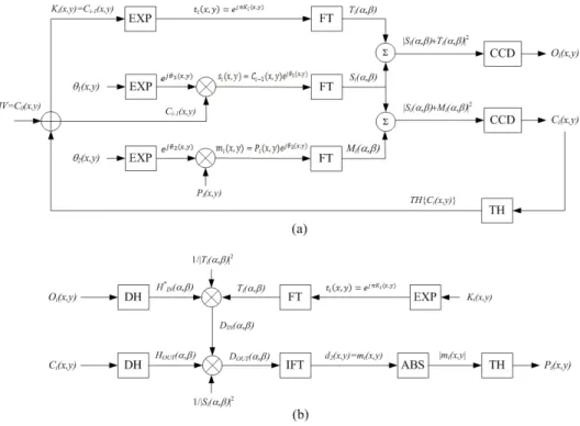
tion to generate the phase distribution, FT and IFT repre-sent the Fourier transform and inverse Fourier transform, Σ denotes a function to perform phase-shifting interferometry, TH denotes a threshold function to generate binary data us-ing a proper threshold value, DH denotes a function to cal-culate a complex hologram, and ABS denotes the absolute-value function.
III. NUMERICAL SIMULATIONS AND SECURITY ANALYSIS
To verify the feasibility of the proposed optical encryp-tion scheme for CFB mode shown in Figs. 1(b) and 2,
nu-merical simulations are carried out using Mathlab. 256 × 256-pixel binary images are used for simulation; the size of the data depends on the display capability of the SLM. For visual convenience, binary images are used as input plain-texts. Figures 4(a)–4(c) show the consecutive plaintexts of binary images to be encrypted in CFB mode. Figure 5 shows intensity distributions of ciphertexts for encrypting the 1st plaintext P1, shown in Fig. 4(a), which are assumed to be recorded on CCDs with 256 gray levels. Figure 5(a) includes intensity distributions of O1 that consist of two interferograms and two DC-term intensities. Two interfero-grams I1,IN1 and I1,IN2 are obtained by performing two-step phase-shifting interferometry in the inner interferometer, FIG. 3. Flowcharts for the proposed scheme. (a) Encryption and (b) decryption.
FIG. 4. Binary images to be encrypted. (a) The 1st plaintext P1, (b) the 2nd plaintext P2, and (c) the 3rd plaintext P3.
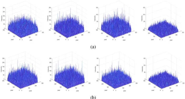
where the phase shift is 0 or π/2 respectively. In addition, the two DC-term intensities IT and IS are Fourier-transform patterns of only the reference wave or the object wave re-spectively. These four intensities of O1 are transmitted to the receiver for retrieval of the previous ciphertext C0. Sim-ilarly, Fig. 5(b) depicts intensity distributions of C1. Two interferograms I1,OUT1 and I1,OUT2 are obtained by performing two-step phase-shifting interferometry in the outer interfer-ometer. The two DC-term intensities IM and IS are Fourier-transform patterns of only the object wave or the reference wave respectively. As shown in Figs. 5(a) and 5(b), the intensity distribution of IS in the inner interferometer is the same as that for the outer interferometer, because the object wave in the inner interferometer is used as the reference wave in the outer interferometer. These four intensities C1 are transmitted to the receiver for decryption of the plain-text P1. From the point view of cryptography, the transmit-ted ciphertexts have a noiselike random intensity pattern, so that an attacker cannot acquire the original image easily.
Figure 6 shows the results of reconstruction and decryp-tion of the consecutive plaintexts Pi (i = 1, 2, 3 ). Figure 6(a) shows a randomly generated binary matrix as the ini-tialization value C0, which is used to encrypt the first-stage encryption key K1. In this paper, K1 is designed to have the same initialization value of C0, for convenience. Figure 6(b) shows the reconstructed intensity obtained from the reconstructed information D1,OUT of Eq. (18) when K1 = C0, resulting in the correctly decrypted plaintext P1 according to the proper threshold value, as shown in Fig. 6(c). Figures
6(d) and 6(e) show the incorrectly reconstructed intensity obtained from the reconstructed D1,OUT and the incorrectly decrypted plaintext P1 by the same threshold value when K1 ≠ C0. Consecutively, the second and third plaintext-encryption procedures are accomplished by using the feedback of the first and second ciphertexts. Each feedback ciphertext for the next encryption procedure is designed to compute XOR logic operation of the four ciphertexts of Ci, expressed as Eq. (20). Figure 6(f) is the first feedback ciphertext of binary pattern C1, which is used in the second-stage plaintext encryption of P2. Figure 6(g) shows the correctly reconstructed intensity obtained from the recon-structed D2,OUT when K2 = C1, resulting in the correctly de-crypted plaintext P2, as shown in Fig. 6(h). Figures 6(i) and 6(j) show the incorrectly reconstructed intensity obtained from D2,OUT and the incorrectly decrypted plaintext P2 when K2 = C0 (instead of the correct C1). Likewise, Fig. 6(k) is the second feedback ciphertext of binary pattern C2, which is used to encrypt the third-stage plaintext encryption of P3. Figures 6(l) and 6(m) show the correctly reconstructed in-tensity and the decrypted plaintext P3 obtained from D3,OUT when K3 = C2, and Figs 6(n) and 6(o) show the incorrectly reconstructed intensity and the incorrectly decrypted plain-text P3 obtained from D3,OUT when K3 = C1 (instead of the correct C2).
To examine the reliability and sensitivity of the proposed method, the decryption error is analyzed. The mean squared error (MSE) between the decrypted plaintext and the origi-nal plaintext is calculated as
FIG. 5. Intensity distributions of the ciphertexts derived from the 1st plaintext P1: (a) O1 (I1,IN1, I1,IN2, IT, IS) acquired from the inner
Optical Encryption Scheme for Cipher Feedback Block... - Seok Hee Jeon and Sang Keun Gil 161 ������(�� �� 0) = |��(�� �)|�+ |��(�� �)|�+ 2|��(�� �)||��(�� �)| ���∆��, (9) ��������� ����� = |��(�� �)|�+ |��(�� �)|�+ 2|��(�� �)||��(�� �)| cos (∆��−��), (10) �������(�� �� 0) = |��(�� �)|�+ |��(�� �)|�+ 2|��(�� �)||��(�� �)| ���∆��, (11) ���������� ����� = |��(�� �)|�+ |��(�� �)|�+ 2|��(�� �)||��(�� �)| cos (∆��−��), (12) ∆��=�−�= ����������������������(�����) �������(�����)�(�����)�, (13) ���= |��||��| =�������������� ����� − (��+ ��)� � + ��������(�� �� 0) − (��+ ��)��. (14) ∆��=�−� = ���������������������(�����) ������(�����)�(�����)�, (15) ���= |��||��| =������������� ����� − (��+ ��)� � + �������(�� �� 0) − (��+ ��)��. (16)
�
����(�� �) =
����� ∗ (���)� �(���) ��=
|��||��|��(�−�) | ��|��� |��|�= |�
�|�
��, (17)�
�����(�� �) =
������(���)��� ����(���)=
|��||��|��(�−�)|��|� | ��|���= |�
�|�
��= �
�(�� �),
(18)�
�(�� �) = ����{�
�����(�� �)}� = |�
�(�� �)| = �
�(�� �), (19)
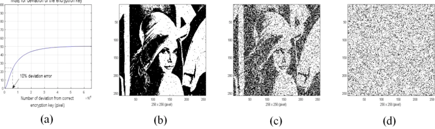
����(�� �) = ����������� � ����������� � ��{��} � ��{��}. (20) ��� =∑ |�(���)��(���)|��� � �×� × 100%, (21) , (21)where P(x, y) denotes the original binary image, d(x, y) denotes the decrypted binary image, and p × q is the image size. At first, an encryption key K is used as the reference wave in the inner interferometer to generate ciphertext Oi. The more the encryption key deviates from the correct key, the more the decrypted image deviates from the original image. The dependence of MSE on the deviation from the correct encryption key K is shown in Fig. 7, where the en-cryption key is assumed to be a binary random distribution and statistical iteration is carried out 100 times for evalua-tion. Figure 7(a) shows the MSE for the decrypted image when the deviation is changed from 1 bit to 256 × 256 bits. From Fig. 7(a), the MSE for the encryption key deviation
approaches about 40% when more than 14,400 bits (about 22% of the key data) deviate from the correct key. Figures 7(b)–7(d) show the decrypted images with MSE = 1.1% in the case of 1% deviation error, MSE = 24.4% in the case of 10% deviation error, and MSE = 50.3% in the case of 100% deviation error respectively. Next, the previous ciphertext Ci-1 is used as the reference wave in the outer interferometer to generate ciphertext Ci. The change of bits in the previous ciphertext can cause incorrect decryption. 100 times itera-tions are also carried out for this MSE evaluation. Figure 8(a) shows that the MSE for the decrypted image increases more slowly than in case of the encryption-key deviation. Figures 8(b)–8(d) show the decrypted images with MSE = 0.4% in the case of 1% deviation error, MSE = 10.1% in the case of 10% deviation error, and MSE = 47.7% in the case of 100% deviation error, respectively. From Figs. 7(a) FIG. 6. Results of reconstruction and decryption of the consecutive plaintexts Pi (I = 1, 2, 3 ): (a) initialization matrix value C0, (b)
and (c) the correctly decrypted plaintext P1 when K1 = C0, (d) and (e) the incorrectly decrypted plaintext P1 when K1 ≠ C0, (f) the 1st
feedback ciphertext C1, (g) and (h) the correctly decrypted plaintext P2 when K2 = C1, (i) and (j) the incorrectly decrypted plaintext
P2 when K2 = C0, (k) the 2nd feedback ciphertext C2, (l) and (m) the correctly decrypted plaintext P3 when K3 = C2, (n) and (o) the
and 8(a), the encryption key in the inner interferometry is more sensitive than the previous ciphertext in the outer interferom-etry for decryption. When the deviation error is 10% of the correct data, the MSE for the encryption key is about 2.5 times as great as that of the previous ciphertext. This high sensitivity means that it is difficult to attack the decryption system.
To discuss the resistance against attacks in the aspect of security, it is assumed that the attacker has a priori knowl-edge of the proposed encryption process, even if it is impos-sible in practice. In this paper we observe that the proposed cryptosystem shows excellent resistance against possible attacks such as known-plaintext attack (KPA), chosen-plaintext attack (CPA), and chosen-ciphertext attack (CCA). According to plaintext and ciphertext attacks, the attacker can get many plaintexts (Pi) and ciphertexts (Oi and Ci) in the proposed CFB encryption scheme. Although the attack-er can calculate the correct complex holograms Hi,IN and Hi,OUT by calculating Eqs. (13)–(16) from the intercepted ciphertexts Oi and Ci due to the known cryptography pro-cess, Di,IN of Eq. (17) should be known and successively the Fourier transform function Ti should be known to decrypt
the plaintext information Mi of Eq. (18). Anyhow, Ti can be inferred from Eq. (17) calculating Ti = (Si IT)/H*i,IN. To find out Si = FT{si}, the attacker must know the function si(x,y) = Ci–1(x, y) ejθ1(x,y), which is represented by multiplication of the previous ciphertext Ci–1 and the random-phase mask exp[jθ1(x, y)]. This means that the attacker can discover Si only if the random-phase-mask function is known, even though the previous ciphertext Ci–1 is known. However, the attacker cannot deduce the random-phase-mask function, because only the transmitter can determine it. Furthermore, the feedback ciphertext for the next plaintext-encryption procedure is determined by XOR logic operation on the ci-phertexts, as in Eq.(20) in the proposed CFB method. Even if all ciphertexts Ci are revealed to the attacker, it is difficult for the attacker to deduce the exact feedback ciphertext if they do not know the combination algorithm of the cipher-texts in the cryptosystem.
V. CONCLUSIONS
We propose a novel optical encryption scheme for CFB FIG. 7. MSE depending on deviation from the correct encryption key K: (a) MSE graph when deviation is changed from 1 bit to 256 × 256 bits, (b) the decrypted image with MSE = 1.1% in the case of 1% deviation error, (c) the decrypted image with MSE = 24.4% in the case of 10% deviation error, and (d) the decrypted image with MSE = 50.3% in the case of 100% deviation error.
FIG. 8. MSE depending on deviation from the correct previous ciphertext Ci-1: (a) MSE graph when deviation is changed from 1 bit
to 256 × 256 bits, (b) the decrypted image with MSE = 0.4% in the case of 1% deviation error, (c) the decrypted image with MSE = 10.1% in the case of 10% deviation error, and (d) the decrypted image with MSE = 47.7% in the case of 100% deviation error.
Optical Encryption Scheme for Cipher Feedback Block... - Seok Hee Jeon and Sang Keun Gil 163 mode, capable of encrypting large two-dimensional (2D)
page data compared to the conventional one-dimensional block data, which is carried out by two-step phase-shifting digital interferometry based on orthogonal polarization, using a quarter-wave plate in the reference beam. The en-cryption is performed in the Fourier domain to record inter-ferograms on CCDs with 256 gray levels, which generates a noiselike random distribution in the ciphertext. In the pro-posed optical CFB scheme, a page of plaintext is encrypted into 2D ciphertexts by applying the dual interferometry to the previous ciphertext, while the conventional CFB method encrypts bits of block plaintext. Ciphertexts are transmitted over a digital information network and then decrypted by digital computation according to the given CFB algorithm. Sequential page encryption is possible in the cryptosystem with a different encryption key. The use of a random-phase mask in the encryption system protects against several types of attack, such as KPA, CPA and CCA, and then the proposed method provides higher security with many more degrees of freedom than the conventional method. Further-more, the proposed method has an additional security ad-vantage because the feedback ciphertext is determined by a specific XOR combination algorithm of ciphertexts known only by the transmitter, which is kept secret from attack-ers. Numerical simulations verify that the proposed optical CFB encryption scheme shows the feasibility of the highly secure CFB mode, due to its reliability against attacks.
ACKNOWLEDGMENT
This work was supported by Incheon National Univer-sity (International Cooperative) Research Grant in 2018.
REFERENCES
1. P. Refregier and B. Javidi, “Optical image encryption based on input plane and Fourier plane random encoding,” Opt. Lett. 20, 767–769 (1995).
2. O. Matoba, T. Nomura, E. Pe´rez-Cabre´, M. S. Milla´n, and B. Javidi, “Optical techniques for information security,” Proc. IEEE 97, 1128–1148 (2009).
3. A. Alfalou and C. Brosseau, “Optical image compression and encryption methods,” Adv. Opt. Photonics 1, 589-636 (2009). 4. W. Chen, B. Javidi, and X. Chen, “Advances in optical
secu-rity systems,” Adv. Opt. Photonics 6, 120–155 (2014). 5. B. Javidi, A. Carnicer, M. Yamaguchi, T. Nomura, E.
Pérez-Cabré, M. S. Millán, N. K. Nishchal, R. Torroba, J. F. Barrera, W. He, X. Peng, A. Stern, Y. Rivenson, A. Alfalou, C. Bros-seau, C. Guo, J. T Sheridan, G. Situ, M. Naruse, T. Matsumo-to, I. Juvells, E. Tajahuerce, J. Lancis, W. Chen, X. Chen, P. W. H. Pinkse, A. P. Mosk, and A. Markman, “Roadmap on optical security,” J. Opt. 18, 083001 (2016).
6. B. Javidi and T. Nomura, “Securing information by use of digital holography,” Opt. Lett. 25, 28–30 (2000).
7. E. Tajahuerce, O. Matoba, S. C. Verrall, and B. Javidi, “Opto-electronic information encryption with phase-shifting interfer-ometry,” Appl. Opt. 39, 2313–2320 (2000).
8. L.-Z Cai, M.-Z He, Q. Liu, and X.-L Yang, “Digital image en-cryption and watermarking by phase-shifting interferometry,” Appl. Opt. 43, 3078–3084 (2004).
9. C. Mela and C. Iemmi, “Optical encryption using phase-shift-ing interferometry in a joint transform correlator,” Opt. Lett. 31, 2562–2564 (2006).
10. X. F. Meng, L. Z. Cai, X. L. Yang, X. X. Shen, G. Y. Dong, and Y. R. Wang, “Two-step phase-shifting interferometry and its application in image encryption,” Opt. Lett. 31, 1414–1416 (2006).
11. H. Li, “Image encryption based on gyrator transform and two-step phase-shifting interferometry,” Opt. Lasers Eng. 47, 45–50 (2009).
12. X. F. Meng, X. Peng, L. Z. Cai, A. M. Li, Z. Gao, and Y. R. Wang, “Cryptosystem based on two-step phase-shifting inter-ferometry and the RSA public-key encryption algorithm,” J. Opt. A: Pure Appl. Opt. 11, 085402 (2009).
13. S.-H. Jeon and S.-K. Gil, “2-step phase-shifting digital ho-lographic optical encryption and error analysis,” J. Opt. Soc. Korea 15, 244–251 (2011).
14. D. Fan, X. Meng, Y. Wang, X. Yang, X. Peng, W. He, G. Dong, and H. Chen, “Asymmetric cryptosystem and software design based on two-step phase-shifting interferometry and el-liptic curve algorithm,” Opt. Commun. 309, 50–56 (2013). 15. B. Javidi and T. Nomura, “Polarization encoding for optical
security systems,” Opt. Eng. 39, 2439–2443 (2000).
16. J. F. Barrera, R. Henao, M. Tebaldi, R. Torroba, and N. Bolog-nini, “Multiplexing encrypted data by using polarized light,” Opt. Commun. 260, 109–112 (2006).
17. U. Gopinathan, T. J. Naughton, and J. T. Sheridan, “Polarization encoding and multiplexing of two-dimensional signals: appli-cation to image encryption,” Appl. Opt. 45, 5693–5700 (2006). 18. N. Zhu, Y. Wang, J. Liu, J. Xie, and H. Zhang, “Optical image
encryption based on interference of polarized light,” Opt. Ex-press 17, 13418–13424 (2009).
19. A. Alfalou1 and C. Brosseau, “Dual encryption scheme of im-ages using polarized light,” Opt. Lett. 35, 2185–2187 (2010). 20. S. K. Gil, “2-step quadrature phase-shifting digital holographic
optical encryption using orthogonal polarization and error analysis,” J. Opt. Soc. Korea 16, 354–364 (2012).
21. T. J. Naughton, B. M. Hennelly, and T. Dowling, “Introducing secure modes of operation for optical encryption,” J. Opt. Soc. Am. A 25, 2608–2617 (2008).
22. S.-H. Jeon and S.-K. Gil, “Optical implementation of cipher block chaining mode algorithm using phase-shifting digital holography,” Opt. Eng. 55, 123112 (2016).