저작자표시-비영리-변경금지 2.0 대한민국 이용자는 아래의 조건을 따르는 경우에 한하여 자유롭게 l 이 저작물을 복제, 배포, 전송, 전시, 공연 및 방송할 수 있습니다. 다음과 같은 조건을 따라야 합니다: l 귀하는, 이 저작물의 재이용이나 배포의 경우, 이 저작물에 적용된 이용허락조건 을 명확하게 나타내어야 합니다. l 저작권자로부터 별도의 허가를 받으면 이러한 조건들은 적용되지 않습니다. 저작권법에 따른 이용자의 권리는 위의 내용에 의하여 영향을 받지 않습니다. 이것은 이용허락규약(Legal Code)을 이해하기 쉽게 요약한 것입니다. Disclaimer 저작자표시. 귀하는 원저작자를 표시하여야 합니다. 비영리. 귀하는 이 저작물을 영리 목적으로 이용할 수 없습니다. 변경금지. 귀하는 이 저작물을 개작, 변형 또는 가공할 수 없습니다.
공학석사 학위논문
Analysis of
Aerodynamic Improvements to solve
Major Environmental Problems in
Domestic Piglet House
국내 자돈사의 주요 환경 문제에 대한 공기역학적
개선 방안 분석
2019 년 2 월
서울대학교 대학원
생태조경
·지역시스템공학부 지역시스템공학전공
김 준 규
Analysis of
Aerodynamic Improvements to solve
Major Environmental Problems in
Domestic Piglet House
국내 자돈사의 주요 환경 문제에 대한 공기역학적
개선 방안 분석
지도교수 이 인 복
이 논문을 공학석사 학위논문으로 제출함
2019 년 2 월
서울대학교 대학원
생태조경
·지역시스템공학부 지역시스템공학전공
김 준 규
김준규의 공학석사 학위논문을 인준함
2019년 2월
위 원 장
(인)
부위원장
(인)
위
원
(인)
Abstract
In recent years, the livestock industry in domestic agricultural production has increased steadily, accounting for about 43%, as meat-oriented consumption has increased. Among them, the production of swine is the largest amount, and farmers are required to mass-produce farms while the number of swine workers in rural areas is decreasing. As a result, many swine facilities are becoming larger and maximizing the production of swine through concentrated breeding in large-scale facilities. However, the control of the internal environment in such a large-scale facility is very close to the productivity of swine. If the internal environment is not properly maintained, feed efficiency will decrease and productivity will be lowered, and it will become vulnerable to disease exposure and lead to death. In particular, young swine is sensitive to environmental changes, which can easily lead to mortality if they do not provide adequate growth conditions during the winter and the summer. For this reason, environmental control swine house is very important.
In many farmhouses, the existing conventional swine houses are remodeled and the ventilation system is different for each farmhouse. Also, farmers operate in an empirical method, so there is not a standardized management for environmental control of swine house. Therefore, in order to maximize the annual production of swine and to reduce the damage caused by diseases, it is becoming increasingly important to control the optimal growth environment through the proper operation of the ventilation system of the facility.
In Korea, various environmental problems are occurring in winter season, summer season, and changing season due to distinct seasonal climate characteristics. The main problems of swine house are internal temperature, humidity, ammonia gas, etc. These environmental factors are dominantly influenced by air flow, which is the main mechanism of diffusion. Therefore, aerodynamic analysis and improvement of seasonal environmental problems are needed to improve the productivity of swine. Numerical studies on the various
conditions inside the swine facility have been conducted through computational fluid dynamics simulation. However, few studies have been carried out to analyze the various ventilation system and environmental condition. In addition, aerodynamic analysis of the existing standard swine house model is insufficient. Therefore, in this study, the main objects are to understand the internal environmental problems mainly occurring in swine house and to evaluate the improvement methods through aerodynamic analysis.
Computational fluid dynamics simulations were performed to analyze various environmental conditions and ventilation systems. Heat, moisture and ammonia were simulated inside the swine house, and a lot of models were developed considering various ventilation system. Model validation was based on previous research results.
As a result of this study, it is suitable to use the ceiling hole inlet type and the pit fan to solve the low temperature problem in the winter season. To solve humidity and ammonia problems at the same time, it is necessary to adjust the ventilation rate. It is appropriate to supplement the temperature by using some heating devices. In summer season, the fan may be overloaded due to excessive air volume when operated with the ventilation rate of 2009 Korean Standard. Because it is possible to control the internal environment of the swine room sufficiently by the ventilation rate based on MWPS, it is suitable to operate with the maximum ventilation rate based on MWPS. In addition, in order to solve the high temperature problem around the swine group, it is effective to use the pipe partition. Based on the results of this study, it is expected that it can be used as basic data for environmental management of domestic swine house.
Keyword : Aerodynamic analysis, Computational Fluid Dynamics (CFD),
Domestic swine house, Environmental control
Contents
Abstract... i
Contents ... iii
List of Tables... v
List of Figures ... vii
1. Introduction ... 10
2. Literature Review ... 14
2.1. Environmental problems and aerodynamic improvements of domestic swine houses in the winter season...14
2.2. Environmental problems and aerodynamic improvements of domestic swine houses in the summer season ...15
2.3. Analysis of micro-climate in domestic swine houses through field experiment and CFD simulation...16
3. Materials and Methods... 18
3.1. Target swine house ...19
3.2. Survey method of environmental problems and aerodynamic improvements in the swine houses ...21
3.3. CFD (CFD) ...22
3.4. Validation of CFD model ...24
3.5. Development of CFD model for evaluating improvement about aerodynamic problems in swine house ...24
3.5.1. Design of the CFD model of target swine house ...24
3.5.2. Design of CFD simulation cases ...27
3.5.2.1. CFD simulation cases in winter season ...28
3.5.2.2. CFD simulation cases in summer season...32
3.5.3. Design of CFD simulation model ...35
4. Results and Discussion... 37
4.1. Environmental problems and improvements in swine houses ...37
4.1.2. Analysis of humidity distribution with minimum ventilation rate...43
4.1.3. Analysis of ammonia distribution with minimum ventilation rate...46
4.1.4. Analysis of infiltration problems in swine house...49
4.1.5. Analysis of temperature distribution with modified ventilation rate...50
4.1.6. Analysis of humidity and ammonia distribution with modified ventilation rate 53 4.1.7. Analysis of improvement method with heater and heating box ...57
4.2. Analysis of environmental problems and aerodynamic improvements in the summer season ...60
4.2.1. Analysis of temperature distribution in swine room using ventilation rate of MWPS ...60
4.2.2. Analysis of humidity and ammonia distribution in swine room using ventilation rate of MWPS ...63
4.2.3. Analysis of temperature distribution in swine room using ventilation rate of 2009 Korean Standard...67
4.2.4. Analysis of humidity and ammonia distribution in swine room using ventilation rate of 2009 Korean Standard...70
4.2.5. Environmental problems and improvements depending on partition type 72
5. Conclusion ... 73
Reference ... 76
List of Tables
Table 1 Specification of the ventilation system according to the case study.... 24
Table 2 Parameters of porous medium for bottom slot in swine room... 25
Table 3 Boundary condition values of CFD simulation ... 26
Table 4 Simulation cases of ventilation system in winter season... 31
Table 5 Ventilation rate of swine house from Korean Standard ... 33
Table 6 Ventilation rate of swine house from MWPS... 33
Table 7 Simulation cases of ventilation system and ventilation rate in summer season... 34
Table 8 Simulation cases of fence type in summer season... 35
Table 9 Ventilation types for CFD simulation ... 35
Table 10 Boundary conditionas for CFD simulation... 36
Table 11 CFD simulation results of temperature distribution in winter season ... 37
Table 12 CFD simulation results of humidity distribution in winter season ... 43
Table 13 CFD simulation results of ammonia gas distribution in winter season ... 46
Table 14 CFD simulation results of temperature distribution using modified ventilation rate in winter season ... 50
Table 15 CFD simulation results of humidity distribution using modified ventilation rate in winter season ... 53
Table 16 CFD simulation results of ammonia distribution using modified ventilation rate in winter season ... 54
Table 17 CFD simulation results of temperature distribution using MWPS ventilation rate in summer season... 61
Table 18 CFD simulation results of relative humidity distribution using MWPS ventilation rate in summer season... 64
Table 19 CFD simulation results of relative ammonia distribution using MWPS ventilation rate in summer season... 64
Table 20 CFD simulation results of temperature distribution using 2009 Korean Standard ventilation rate in summer season ... 68
Table 21 CFD simulation results of humidity distribution using 2009 Korean Standard ventilation rate in summer season ... 70 Table 22 CFD simulation results of ammonia distribution using 2009 Korean
List of Figures
Fig. 1 Flow chart of this study to analyze main aerodynamic problems using
CFD simulation ... 18
Fig. 2 Geographical information of target area ... 19
Fig. 3 Schematic information of target swine house (Korean Standard, 2009)20 Fig. 4 Top and side views of target swine house (Korean Standard, 2009)... 21
Fig. 5 Field experiments and interview for collecting main problems of swine houses... 21
Fig. 6 Various materials of literature survey for the analysis of main problems in domestic swine houses ... 22
Fig. 15 Computational domain of target swine house ... 27
Fig. 16 Case study of CFD simulation for analysis of main problems in swine house ... 28
Fig. 17 Ventilation system of swine house for controlling micro-climate... 29
Fig. 18 Ventilation fan of swine house (Side fan, chimney fan, pit fan) ... 30
Fig. 19 Heating box and light bulb heater in swine house... 31
Fig. 20 Fence type of swine house (panel & pipe) in swine house ... 34
Fig. 21 Average temperature around the swine according to the ventilation system... 39
Fig. 22 Minimum temperature around the swine according to the ventilation system... 39
Fig. 23 The contour of temperature near the swine according inlet type ... 41
Fig. 24 The swine groups divided by partition ... 42
Fig. 25 Minimum temperature around the swine according to the ventilation system... 43
Fig. 26 Temperature and velocity distribution using duct inlet type according to hole interval ... 43
Fig. 27 Relative humidity around the swine according to the ventilation system ... 45 Fig. 28 The contour of relative humidity near the swine according inlet type 46
Fig. 29 Ammonia concentration around the swine according to the ventilation system... 47 Fig. 30 The contour of ammonia concentration near the swine according inlet
type... 48 Fig. 31 The contour of ammonia concentration near the swine according inlet
type... 49 Fig. 32 The simulation results of the infiltration in cracks (door, shutter)... 50 Fig. 33 Temperature around the swine according to the ventilation using
modified ventilation rate ... 52 Fig. 34 Temperature contour according to the ventilation using modified
ventilation rate... 53 Fig. 35 Relative humidity around the swine according to the ventilation using
modified ventilation rate ... 54 Fig. 36 Ammonia concentration around the swine according to the ventilation
using modified ventilation rate... 56 Fig. 37 Temperature distribution around the swine according to the ventilation
using heater and heating box... 57 Fig. 38 Simulation results of preventing temperature problems by bloking cold
air using heating box ... 58 Fig. 39 Contours of the temperature, humidity, ammonia gas using heater and heating box... 59 Fig. 40 Temperature distribution around the swine using MWPS ventilation
rate in summer season ... 62 Fig. 41 Contours of the temperature distribution using MWPS ventilation rate in summer season... 63 Fig. 42 Contours of the relative humidity distribution using MWPS ventilation
rate in summer season ... 67 Fig. 43 Contours of the ammonia distribution using MWPS ventilation rate in summer season... 67 Fig. 44 Temperature distribution around the swine using 2009 Korean
Standard ventilation rate in summer season ... 69 Fig. 45 Vector field and temperature contour near the swine group according
1. Introduction
Domestic agricultural output is steadily increasing every year, and the output of animal husbandry is about 20 trillion won as of 2017, reaching 44% of total agricultural output. Among them, the annual output of swine is about 6 trillion won, which is the largest amount in all the species. This phenomenon is due to the recent increase in consumption of pork due to changes in meat-eating habits, and the mass production of swine is required. Therefore, domestic swine production facilities are being changed to maximize production. In fact, the number of swine farm households has been steadily decreasing since the year 2000, and the number of swine farming is steadily increasing every year, which means that the facilities are being enlarged and densely packed (Statistics Korea, 2017). In addition, as the import of pork has increased in accordance with the WTO system, interest in the domestic swine industry has been continuously increasing to secure competitiveness (Choi et al., 2014). In order to improve productivity and compete with developed countries, modernization of facilities, improvement of quality of feed, improvement of breeding, improvement of specification management and prevention of diseases are needed. Quality of feed, improvement of breeding and management of specifications have improved much compared to the past, but the improvement of swine facilities is insufficient. Control of the internal growth environment is crucial to improve productivity in these backward facilities (Kwon et al., 2016). If the internal environment is not properly controlled, the rate of growth of swine will decrease and the output of swine will decrease. In addition, the immune system weakens and can become vulnerable to the disease. Especially, in the case of young swine susceptible to changes in the external environment, a large number of deaths can occur when the appropriate growth environment is not established. Therefore, in order to reduce the mortality rate and increase the productivity, it is very important to control the environment inside the facility.
swine facility during the period when the extreme environments such as summer and winter are formed due to the distinctive climate characteristics of the four seasons. In winter, the distribution of internal environment differs according to the ventilation structure, which makes it difficult for farmers to predict low temperature stress. (Song et al., 2004; Moon et al., 2013; Jung, 2014). In the old facilities, external air enters between the ventilation openings of the old ventilation fan or the door, resulting in deterioration of the internal warmth, resulting in an increase in the cost of heating energy and an uneven distribution of the internal environment. Such low temperature stress is a factor that lowers swine feed efficiency and can weaken various respiratory disease immunity. As a result of this temperature problem, many farmers do not ventilate very much in order to cut off external cold air and reduce heating costs (Lee et al., 2014). The moisture content and the ammonia gas accumulate in the facility so that the productivity may deteriorate and the quality of the meat may be deteriorated (Yasuhara et al., 1984; Schiffman et al., 1998; Ni et al., 2000; Lee et al., 2006). In summer, there is a high-temperature stress problem caused by the high-temperature rising due to the heat of swine in the facility (Kim et al., 2012; Moon et al., 2013; Jung et al., 2014). In addition, the odor and gas inside the facility spread to the outside, and the complaints are increasing in the nearby farms (Yasuhara et al., 1984; Den Brok et al., 1997; Schiffman et al., 1998; Ni et al. 2000; Yoon et al., 2012), Problems of wind stress caused by excessive flow velocity of swine are being discussed.
The environmental problems that arise in the facility during the winter and summer are mainly caused by improper formation of temperature, humidity, gas concentration, and flow rate inside the facility. Since the main mechanism of these environmental factors is air flow, accurate analysis and understanding of air flow is essential (Lee et al., 2006). Because most of the environmental control of swine is done through ventilation, proper ventilation system should be built for the farmhouse situation. For this purpose, aerodynamic analysis and improvement of seasonal environmental problems are needed.
A variety of studies have been conducted on aerodynamic improvement measures to solve major environmental problems in swine house. Field experiments have been carried out on the distribution of internal environmental factors by measuring temperature, humidity, ammonia gas concentration, and flow rate in swine houses (Jang et al., 1999; Kim et al., 2004; Lee et al., 2005; Song et al., 2002; 2005; Yoo et al., 2004; 2010; Hong et al., 2008; Kim et al., 2008; 2012; Lee et al., 2014; Moon et al., 2015; Kim et al., 2017). Song et al. (2002) analyzed the efficiency of the duct ventilation system based on temperature, humidity, and flow data near the swine, measured at three points in height in the swine room. Yoo et al. (2010) evaluated suitability based on the field test results to propose a suitable ventilation system for swine. However, studies conducted through field experiments have limitations in that they can only be analyzed for fixed ventilation systems in the target facility. Recently, a variety of researches have been conducted to analyze the distribution of environmental elements in the swine house through computational fluid dynamics (CFD) (Lee et al., 2006; Lee et al., 2008; Seo et al., 2008; 2014; Min & Kim, 2008; Kwon et al., 2010; Lee et al., 2010; Hong et al., 2012; Choi et al., 2014; Lee et al., 2016; Kim et al., 2017). Most of the studies have suggested the problems that occur in swine by measuring internal temperature distribution and humidity. Kwon et al. (2016) used CFD to analyze the factors of dust in the swine house. Since these studies have concentrated on the analysis of specific environmental factors, there are few studies to analyze the various ventilation structures and environmental factors in detail. In some studies, environmental factors were analyzed by measuring the internal environment in the swine room, but the ventilation conditions were not evaluated to improve them. In addition, various environmental problems arise according to the season, so a comprehensive analysis of problems and improvement measures is necessary.
Therefore, in this study, the environmental problem and improvement methods which are mainly occurred in Korean domestic swine house were evaluated. In order to analyze various environmental problems occurring in swine
house, literature survey was carried out together with field survey. Also, CFD was used to evaluate seasonal major environmental problems and aerodynamic improvements according to various ventilation structures. For this purpose, a CFD model for ventilation structure was designed for the target swine houses, and simulations were performed for representative environmental problems by season. The simulation results were analyzed to evaluate the effects of aerodynamic improvement measures on environmental problems in domestic swine houses.
2. Literature Review
2.1.
Environmental
problems
and
aerodynamic
improvements of domestic swine houses in the winter season
There are three main types of problems that can occur in the swine house in winter season. First, the temperature problem was mentioned as the main problem (Jung et al., 2014; Kim et al., 2015; Lee et al., 2016; Yoo et al., 2016). In particular, if the temperature is lowered due to failure to maintain proper growth temperature in winter, the body's immunity will be lowered due to low temperature stress, which can easily be exposed to various diseases. In order to maintain the body temperature of swine, feed efficiency can be reduced. (Lee et al., 2016). Also, in case of temperature-sensitive swine, if the ventilation structure is not designed properly, there may be a problem that the outside cold air can reach to the swine directly, and considering the habit of keeping the swine together to maintain the body temperature. Depending on the ventilation structure of the swine house, the internal temperature may be unevenly distributed, resulting in a lowered rate of growth in certain areas and an increase in mortality. To overcome these problems, it was investigated to improve the ventilation system during the winter season to minimize the area where cold stress was generated, and to install and operate the heating system in some low temperature areas to maintain the optimal environment in the swine house (Song et al., 2004; Yoo et al., 2016; Lee et al., 2016). Especially, most of the causes of cold stress in swine houses are due to the inability of the farmers to grasp the flow of internal air. Therefore, it is essential to have a clear understanding of the external cold air inflow path and internal flow. Secondly, the problem of ammonia gas was analyzed (Ni et al., 2000; Song et al., 2004; Lee et al., 2006; Kim et al., 2014; Lee et al., 2015). In winter, when low-temperature outside air flow into the swine house, it is necessary to heat more in the swine room, so in order to save heating costs, most farmers ventilate less than the minimum ventilation amount or block the entrance (Kim et al., 2014). As a result, toxic gases
(ammonia, methane gas, etc.) coming from the manure in the pit can accumulate excessively in the swine room (Kim et al., 2013). Due to the accumulated harmful gas, the immunity of swine can be reduced and they are easily exposed to various diseases. Even if excessive gas accumulation and odor occur near the swine, it is not easy to detect it at the height of the worker. Also, since the swine is likely to damage the equipment in the lower position, the equipment measuring them is installed at a position higher than that of the swine, so that the badness and the seriousness of the ammonia gas near the swine can not be easily grasped (Kim et al., 2014; Lee et al., 2015). The third is the infiltration phenomenon that occurs between the door of the pawn shop and the fan shutter of the ventilation fan (Song et al., 2009; 2010). Failure to ensure the confidentiality of the facility may result in unintentional inflow of cold air. Especially during the winter season when the amount of ventilation is kept low, the flow of air may be changed due to such unnecessary inflow, and the efficiency of internal ventilation may be decreased. In addition, when cold air is reached, low temperature stress can be caused.
2.2.
Environmental
problems
and
aerodynamic
improvements of domestic swine houses in the summer
season
In the summer season, the temperature inside the swine house rises due to the breathing and fever of swine in room, and high-temperature stress such as heat island phenomenon is a typical problem (Kim et al., 2009; Kwon et al., 2012; Song et al., 2012; Lee et al., 2014). Especially, in case of high temperature stress, sufficient ventilation and temperature reduction measures are essential. To improve this, it is necessary to improve ventilation system through aerodynamic analysis of internal environment. When the ventilation system is operated with the maximum ventilation rate during the summer, the internal temperature environment can be influenced by the external weather conditions, so the location of the inlet and outlet is very important (Kim et al., 2012). Humidity, along with temperature, is also a
factor affecting the health of swine, and there is a relativity between them. If the temperature is too high, the humidity may be low, and if the humidity is high, the temperature management may become difficult. Humidity control is important because it affects the growth of viruses, bacteria, and fungi. Humidity below 60% can cause damage to the respiratory system. Therefore, the humidity inside the swine house should be controlled to maintain 60 ~ 70%. For this purpose, appropriate ventilation should be performed considering the moisture content in the swine room and the external humidity. The humidity can be very high due to the rainy season in the summer, and humidity control can be difficult because the water spray system is mainly used when the cooling system in the swine house is used. Accordingly, it is necessary to control the excessive increase of the internal humidity through appropriate ventilation control. In addition, due to the non-uniform temperature distribution, it is difficult for the farmers to recognize the invisible environmental factors even if the inadequate environmental distribution at a specific location appears. Also, unlike in winter, the air flow rate in the swine room is considerably higher in the summer when the maximum ventilation is implemented. It has been mentioned that the productivity can be reduced due to influence on the sensation temperature of the swine (Yoo et al., 2004; Lee et al., 2016). In summer there may be a number of problems due to concentrated animal feeding operation as well as high temperature problems. Excessive concentrated breeding not only lowers the resistance to diseases due to the decrease of the immunity of the swine but also decreases the productivity because the sufficient amount of activity space is not secured and the feed intake is decreased.
2.3. Analysis of micro-climate in domestic swine houses
through field experiment and CFD simulation
Many field experiment have been conducted on various problems occurring in domestic pig farms (Jang et al., 1999; Kim et al., 2004; Lee et al., 2005; Song et al., 2002; 2005; Yoo et al., 2004; 2010; Hong et al., 2008; Kim et al., 2008; 2012; Lee
et al., 2014; Moon et al., 2015; Kim et al., 2017). Environmental factors such as temperature, humidity, and ammonia gas concentration were evaluated by installing environmental measuring equipment inside the swine house, and studies for suggesting improvements were conducted. Kim et al. (2004) proposed a problem based on the measurement of temperature, flow rate, and ammonia gas concentration according to the ventilation system and recommended a proper ventilation system. However, the internal air flow can be changed according to the ventilation rate and the position of the ventilation structure. Also, it is difficult to judge the uniformity of the distribution because it is represented by the value measured at the limited point. In order to overcome experimental limitations in the field, analysis by CFD is actively proceeding (Lee et al., 2006; Lee et al., 2008; Seo et al., 2008; 2014; Song et al., 2008; Kwon et al., 2008; Min & Kim, 2008; Kwon et al., 2010; Lee et al., 2010; Hong et al., 2012; Choi et al., 2014; Lee et al., 2016; Kim et al., 2017). CFD has the advantage of being able to perform various analyzes with various internal environmental conditions. Song et al. (2008) conducted field experiments and CFD simulations to analyze the characteristics of air flow according to the ventilation characteristics for controlling the internal environment of the livestock facilities. In addition, Seo et al. (2014) verified the possibility of airborne spread of virus, which is the cause of swine disease, through field experiments and developed a CFD simulation model. The field experiment and CFD study on the environmental factor and the ventilation structure in the swine houses have been progressing steadily. However, there have been few study in which the weather condition, the environmental conditions inside the swine room, and the ventilation structure are taken into consideration. Particularly, since the criteria for maintaining appropriate growth conditions of elements such as temperature, humidity, and gas are different, a comprehensive evaluation according to the ventilation structure needs to be performed.
3. Materials and Methods
Fig. 1 Flow chart of this study to analyze main aerodynamic problems using CFD simulation
Fig. 1 describes the procedure for analysis of main aerodynamic problems in the domestic swine houses. First, field experiments and literature survey were conducted to analyze aerodynamics problems occurring in domestic swine facilities. Because the environmental conditions were different according to the area where the swine facility is located and the growth environment were all diverse, a comprehensive investigation was needed. Diseases, such as epidemics, may spread during winter season, resulting in that it impossible to visit many farms. Therefore, we conducted an additional literature survey to investigate various problems. The literature survey examined research data on domestic pig farms, national farming data, reports, and based on the survey results, seasonal environmental issues were identified.
Next, in order to design the CFD model of the target swine, CFD accuracy validation and field experiment to derive the optimal turbulence model were conducted. Based on the validation results, a CFD model of the target swine house was designed, and simulations were conducted on the seasonal major
environmental problems. Finally, simulation results were analyzed and The improvement of each problem are suggested.
3.1. Target swine house
In order to simulate the various environmental problems occurring in domestic swine house using CFD simulations and to analyze the aerodynamic improvement measures for each problem, the target area was first selected as a representative region of the domestic climate. In particular, the central region is the most populated place for domestic swine facilities, and it is selected as the central region because there are many common problems. Among them, Cheong-ju (latitude: 36 ° 639 ', longitude: 127 ° 441') selected as an area (Fig. 2).
Fig. 2 Geographical information of target area
In the case of swine facility in Korea, there are many cases in which standard design is not used compared to other types of animal, and the design of facilities is not standardized. Therefore, in this study, “2009 Korean Standard of pig houses” was selected as the target facility. Based on this target facilities, ventilation
structures utilized in various farms were considered to be combined. Young swine is more susceptible to environmental changes than finishing swine. Also, internal environmental conditions have a great impact on mortality of young swine. Therefore, young swine was selected as the target animal.
Fig. 3 Schematic information of target swine house (Korean Standard, 2009)
The swine room size was 5.5 m wide, 9.0 m long, 2.4 m high, and the height of the pit is 1.5 m for the removal of swine manure, considering the thickness of the ground and the height of the manure. In order to take into account all ventilation systems, the ventilation system was adapted to use sidewall fans, chimney fans, and pit exhaust fans. The inlet type was to utilize the side wall and the ceiling. The swine room was divided into four zones by fence, and there was one feeder in each zone. There was a passage through which workers and swine can move from the entrance to the opposite wall of the corridor. The material of the floor was made of plastic bag for swine. Fig. 4 is a side view, cross-sectional view, and plan view of the swine room.
Fig. 4 Top and side views of target swine house (Korean Standard, 2009)
3.2. Survey method of environmental problems and
aerodynamic improvements in the swine houses
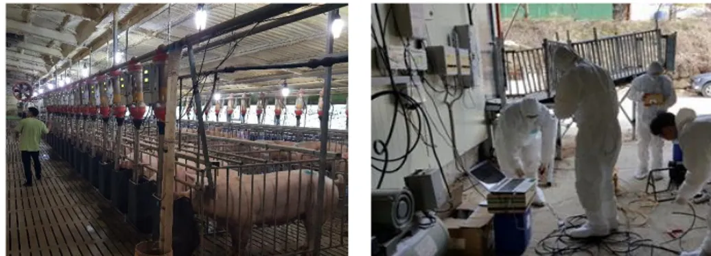
In this study, in order to make aerodynamic approach to various environmental problems, various problems occurred in domestic facilities should be investigated. Field survey and literature survey were conducted to investigate the problems of swine facilities. Field surveys were conducted based on field experiments and interviews with farmers and consultants.
Fig. 5 Field experiments and interview for collecting main problems of swine houses
depend on the external environment, the size of the facilities, and the way of management. Although it is the most intuitive way to investigate the problem by visiting the farm directly, it may take a lot of time and cost to carry out the field investigation considering the difference between the farm. Therefore, in this study, the main problems of domestic swine houses were analyzed by focusing on the literature survey as well as the field experiment.
Literature surveys include analysis of research papers, report data related to swine company, news, articles, and agricultural data issued by major national institutions including RDA, NIAS. Problems and causes of domestic swine are summarized according to the season and problems using the tables. The major causes and their solutions are also summarized separately.
Fig. 6 Various materials of literature survey for the analysis of main problems in domestic swine houses
3.3. CFD (CFD)
CFD simulation is a numerical method for solving the Navier-Stokes equation using discretization methods: finite difference method (FDM), finite element method (FEM), finite volume method (FVM), etcetera. Fluid flow and energy were analyzed by solving the mass conservative equation (1), momentum conservative equation (2), and energy conservative equation (3) (ANSYS Fluent User’s Guide, 2013). CFD simulation has also been actively applied and used in the field of agricultural engineering. In this study, the commercial software DesignModeler (ver. 18.1, ANSYS Inc., PA, USA) and ANSYS FLUENT (ver. 18.1, ANSYS Inc.,
PA, USA) were used. DesignModeler was used to design a three-dimensional grid and numerical calculation domain. FLUENT was used to compute the governing equation of air flow. Numerical analysis is simulated using finite difference method (FVM) for the Navier-Stokes equations of nonlinear differential equations. Mass, energy and momentum conservation laws are applied to each grid network, and after the discretization process, numerical analysis is performed to analyze the fluid flow. Mass, momentum and energy conservation laws applied to CFD are given in Eq. 1, Eq. 2, Eq. 3 (Launder and Spalding, 1974).
+ ∇ ∙ ( ⃗) = (1) ( ⃗) + ∇ ∙ ( ⃗ ⃗) = −∇P + ∇τ + ρ ⃗ + ⃗ (2) ( ) + ∇ ∙ ⃗( + ) = ∇ ∇T − ℎ ⃗ + ( ̅⃗) + (3) Where, : Total energy (J) : Density (kg·m-3) ⃗ : Velocity (m·s-1)
: Constant pressure (Pa) ̅ : Stress tensor (Pa)
⃗ : Gravitational acceleration (m·s-2)
⃗ : External force vector (N·m-3)
: Mass source (kg·m-3)
: Heat transmission coefficient ⃗ : Component of diffusion flux
3.4. Validation of CFD model
In this study, accuracy and turbulence model validation for the CFD simulation of swine were taken from previous research results. Kim et al. (2017) measured air flow, heat environment distribution, and ventilation rate in a swine house through a field experiment and validated the CFD model. In this study, optimum grid size and turbulence model are used as 0.2m and realizable k-w.
3.5. Development of CFD model for evaluating improvement
about aerodynamic problems in swine house
3.5.1. Design of the CFD model of target swine house
In order to design the CFD simulation model, 3D geometry modeling was carried out according to the 2009 Korean Standard. The ventilation system and structures were different according to each case and the model was designed for each case. The type of inlet of the facility and the specifications of the exhaust fan are shown in Table 1.
Table 1 Specification of the ventilation system according to the case study
Inlet Type Outlet Type Side slot Ceiling Duct Side fan Chimney
fan Pit fan Hole Slot Interval
30°, 45°, 90° - 45°, 90° Same, Wider, Narrower D600 D600 D200 14 holes
The bottom of the swine room is suggested to use a plastic slat. However, when the bottom was designed to be the same as the actual shape, the number of mesh can increase. Therefore, the bottom was designed as a porous medium for efficiency of computation. When passing through the porous medium zone, the resistive element against the flow in the x, y and z axes can be calculated by the following Eq. 4 (Bjerg et al., 2008).
∆ = 0.5 × × × + × (4) Where,
∆p : Pressure drop over the porous media volume (Pa) R : Internal resistance factor
R : Viscus resistance coefficient Ρ : Air density (kg/m3)
v : Air velocity, through porous volume (m/s) μ : Viscosity of air (kg m2s-1)
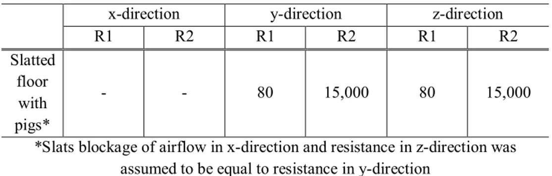
In this model, previous research results were used to calculate the porous medium parameters of the slot (Bjerg et al., 2008). Since the slotted shape in the x direction completely blocks the flow of air, it is replaced by a sufficiently large value (Table 2).
Table 2 Parameters of porous medium for bottom slot in swine room
x-direction y-direction z-direction R1 R2 R1 R2 R1 R2 Slatted floor with pigs* - - 80 15,000 80 15,000 *Slats blockage of airflow in x-direction and resistance in z-direction was
assumed to be equal to resistance in y-direction
The boundary condition for the CFD simulation are shown in the following Table 3. Based on the results of the weather data analysis, the weather conditions of winter and summer are applied. Moisture generated from swine can be classified into respiration, bottom manure, and nipples. The moisture generation rate was calculated based on previous research results. Hayes et al. (2013) measured the amount of moisture produced in the swine room without cleaning the slurry. Based
on this, a regression equation for water content in manure was derived. The amount of moisture produced through the respiration was set to the velocity inlet condition in CFD model by considering the mouth area of the swine on the basis of the average breathing capacity of the swine (about 18 l / min). Since the amount of ammonia gas generation occurs on the manure under the pit slot, the ammonia mass per unit time and area is utilized on the manure surface to similarly simulate it. The values used at this model are obtained from the experiments in the previous research and are shown in Table 3.
Table 3 Boundary condition values of CFD simulation
Boundary Condition Value Reference Winter Summer Outside Temperature -2.5 ( )℃ 30.5 ( )℃
30-year weather data analysis of target site
Winter night & summer daytime (poor condition) Absolute humidity 0.0023 (kg/kg-da) 0.0196 (kg/kg-da) Surface temperature of a pig 39.6 ( )℃ 39.7 ( )℃ Seo et al., 2008 Surface temperature of ceiling 20.3 ( )℃ 31.3 ( )℃ Wagenberg et al., 2004; Min et al., 2008; Seo et al., 2008; Bjerg et al., 2013; Choi et al., 2014; etc. Indoor wall temperature 19.7 ( )℃ 30.4 ( )℃ Outside wall temperature 19.2 ( )℃ 31.2 ( )℃ floor temperature 18.6 ( )℃ 26.2 ( )℃ Ammonia generation rate 3.8086e-7 (kg/m2s) 5.30476e-7 (kg/m2s) Chang et al., 2001; Kim et al., 2008;
from manure Kwon et al., 2008; Lee et al., 2010; Kam et al., 2011; Li et al., 2015; etc. Moisture generation Breath 4.332 (g/s) 7.932 (g/s) Hayes et al., 2013; Lee et al., 2015; etc. Manure 0.4832 (g/s) 1.0432 (g/s) Heater 149.7 ( )℃ - Kwon et al., 2008
Fig. 7 Computational domain of target swine house
3.5.2. Design of CFD simulation cases
In winter, 120 cases were classified into ventilation system, heating system, and infiltration problem. In the summer, 100 cases were classified into ventilation system, ventilation rate and partition type (Fig. 16). In order to analyze the environmental changes of the swine according to time step, the unsteady analysis was performed and the temperature, humidity, and ammonia of the swine were analyzed after 10 minutes (600 seconds) And to evaluate the measures.
Fig. 8 Case study of CFD simulation for analysis of main problems in swine house
3.5.2.1. CFD simulation cases in winter season
Main problems occurring in swine farms during the winter season are mainly cold stress, gas, odor, and infiltration. In order to derive the micro-climate and optimal ventilation method in swine house, cases showing the problem and solving the problem were selected. In particular, the ventilation system has the greatest influence on the internal environment because it is a forced ventilation system. Therefore, the ventilation system was classified into inlet system and outlet system. In addition, it is possible to overcome the internal low temperature stress through the installation of the heating device in the winter season, but the temperature, humidity, gas and flow rate can be affected by the heating device. Therefore, the case to see the difference according to the heating device was selected, and infiltration, one of the most severe damages in the winter season, was selected.
Fig. 9 Ventilation system of swine house for controlling micro-climate
Because the facilities in this study are structured with forced ventilation system, the changes of the environmental factors in the livestock can be very different depending on the ventilation system. There are many cases in which most of the farms in winter do not ventilate very much. Therefore, in the winter season, the internal air quality may vary depending on which ventilation structure is selected.
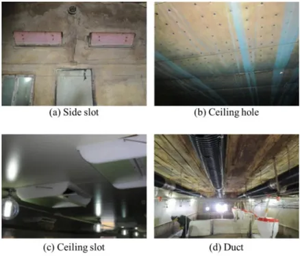
First, in the case of the inlet type of a swine room, side slot, ceiling slot, ceiling hole, and duct type are mainly used. The side slot type can be adjusted in the angle and the direction of airflow. In the winter season, the inside of the corridor creates a temperature similar to that of the outside air, and when it enters the side slot, the cold air may reach the swine near the sidewall. Therefore, in this study, the possibility of cold stress due to this inlet type was selected as the calculation case. When such a problem occurs, the farmhouse can adjust the angle of the side slot so as to send air to the upper of the swine room so that the cold air does not directly reach the swine. The ceiling inlet type is a method of making a
certain space at the upper part of the swine room and utilizing the stagnation zone of the air. It warms the temperature in the buffer zone similar to the temperature of the swine room. The way of entering into the swine room from this ceiling can be divided into the slot type and hole type. In the type of ceiling slot method, the slots are installed at regular intervals in the ceiling, and the slot is opened and closed, and the angle is adjusted to flow into the inside. In the case of the ceiling hole type, a large number of holes are uniformly distributed in the ceiling area, thereby minimizing the inflow speed of the air and spreading the fresh air evenly inside the swine room. The duct type inlet is a method in which air flows through a bellows-pipe having holes. Since the duct bellows-pipe extends from the side wall to the outside, the uniformity in the room can be improved. Because air inflows through these holes and the distribution of environmental factors such as internal temperature and flow rate may be different depending on the interval of these holes, this is selected as the computation case.
Fig. 10 Ventilation fan of swine house (Side fan, chimney fan, pit fan)
There are side fan, chimney fan and pit fan for ventilation. Depending on the farmer, one exhaust fan is installed for using four seasons, or various exhaust fans are installed to selectively operate according to the season (Fig. 18). The side fan is installed on the outer wall of a swine room, and the air is ventilated by operating the side fan. The chimney fan is installed on the ceiling. In the case of two types, because the exhaust direction is different, the distribution of internal environmental factors may be different. The pit fan is used to remove noxious gases such as
ammonia and hydrogen sulfide, which are generated mainly in the manure.
Table 4 Simulation cases of ventilation system in winter season
Conditions Number of Cases Inlet type
Side slot (30°, 45°, 90°) 3 Ceiling (hole, slot (45°, 90°)) 3 Duct (equal, narrow, wide) 3 Outlet type Side, Chimney, Pit fan 3 Ventilation rate Minimum, Modified 2 Total cases 54
(=(3+3+3)×3×2) (2) Heating devices
Fig. 11 Heating box and light bulb heater in swine house
In winter season, minimum ventilation is required to control various environmental factors such as internal harmful gas and humidity. However, in most farms, ventilation is rarely activated in order to minimize the cold stress of swine caused by external cold air. Ventilation should be carried out with the recommended minimum ventilation rate and the heating devices are essential to reduce such cold stress. The main heating devices used in the swine room are a
heating box and a light bulb heater (Fig. 19).
3.5.2.2. CFD simulation cases in summer season
Main problems in swine house in the summer season include high temperature stress, wind stress due to excessive flow rate, and high humidity environment. In particular, the temperature inside the swine is elevated due to the heat of the swine, and even if fresh air is supplied to the outside, it can cause wind stress, which may change according to various ventilation structures. Therefore, the simulation cases were selected considering all possible ventilation structures and structure types affecting the internal flow.
(1) Ventilation system
The inlet type was considered in the case of the side slot type, ceiling slot type, ceiling hole type and duct type in the same way as in the winter season. In the summer, swine would increase their heat and moisture emissions through respiration, and heat and moisture can accumulate around the swine, which can be a significant stress factor for swine. Therefore, in order to understand the temperature, humidity, and ammonia gas, ventilation type was considered. The side fan, chimney fan, and fit fan were used. However, in order to satisfy the maximum of ventilation rate during the summer, several ventilation fans must be operated simultaneously according to the capacity of the ventilation fan.
(2) Ventilation rate
Table 5 Ventilation rate of swine house from Korean Standard
m3/hr Cold Mild Hot Remarks
Gestating Sow Mild ×10~20% 150 ×Hd Mild ×350~500%
After calculating the appropriate ventilation rate, the minimum ventilation
rate and the maximum ventilation
rate are calculated as a ratio to the appropriate ventilation rate. Sow and Litter Mild ×10~20% 250 ×Hd Mild ×350~500% Nursery pig Mild ×20% Weight ×1.3×Hd Mild ×350~500% Finishing pig Mild ×10~20% Weight ×Hd Mild ×350~500%
In 2009 Korean Standard, the US MWPS data and the European standard are applied, considering the special weather conditions in South Korea. In the winter season, the minimum ventilation rate is used to prevent low internal temperature and to remove harmful substances. In the summer season, the maximum ventilation rate is used to prevent the internal high temperature phenomenon. The purpose of this case study was to evaluate the revised Korean Standard ventilation rate by comparing with MWPS ventilation rate (Table 6).
Table 6 Ventilation rate of swine house from MWPS
Animal type Weight Lb Cold Weather Mild Weather Hot Weather (f3/m/hd)
Sow and litter 400 20 80 500 Prenursery pig 12-30 2 10 25 Nursery pig 30-75 3 15 35 Growing pig 75-150 7 24 75 Finishing pig 150-220 10 35 120 Gestating sow 325 12 40 150 Boar 400 14 50 300
Table 7 Simulation cases of ventilation system and ventilation rate in summer season
Conditions Number of Cases Inlet type
Side slot ( 45°, 90°) 2 Ceiling (hole, slot (45°, 90°)) 3 Duct (equal, narrow, wide) 3 Outlet type Side, Chimney, Pit fan 3 Ventilation rate MWPS, Korean Standard 2 Total cases 72
(=(2+3+3)×3×3) (3) Fence type
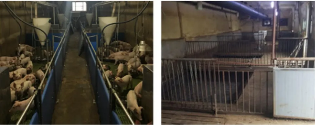
Fig. 12 Fence type of swine house (panel & pipe) in swine house
It is supposed to install the partition so that the swine can be kept in a uniform manner. However, the distribution of the internal environment may vary depending on the shape of the partition. For example, there are various types of partitions such as PVC panel type, metal pipe type, concrete and so on. In the case of the panel type, the partition is in the form of a plate, which blocks air flow through the partition. Many farmers use this type of partition to prevent epidemics from spreading from the mouth to the mouth of swine. Particularly, the PVC type partition is mainly used in the swine room and can be easily separated and reassembled. On the other hand, pipe type and concrete type are mainly used in
finishing pig and they are firmly fixed so that they do not easily fall into the movement of pigs. Because there is a gap between the partitions, the air flow is smooth. Therefore, in the case of performing the maximum ventilation rate in the summer season, the air flow can be changed according to the partition shape.
Table 8 Simulation cases of fence type in summer season
Conditions Number of Cases Inlet type Side slot ( 45°, 90°) 2
Ceiling (hole, slot (45°, 90°)) 3 Outlet type Side+Chimney+Pit fan 1 Ventilation rate MWPS, Korean Standard 2
Total cases 10 (=(2+3)× 1 × 2)
3.5.3. Design of CFD simulation model
The schematic diagram of the facility, the type and characteristics of the ventilation, and the dimensions of the exhaust fan are shown in Table 9 below.
Table 9 Ventilation types for CFD simulation
Inlet Type Outlet Type Side slot Ceiling Duct Side
fan
Chimney fan
Pit fan Hole Slot Interval
30°, 45°, 90° - 45°, 90° Equal, Wider, Narrower Φ600 Φ600 Φ200 14 holes
The environmental conditions according to all operation case conditions of the piglets are shown in the following Table 10. For the temperature of surface, the temperature data obtained from the field test at the time when the temperature was most similar to the external weather are used. Water content in swine room can be classified into respiration generation rate, humidity of manure and nipples. Hayes
et al. (2013) measured the amount of water produced in the swine room without cleaning the room. Since the size of the swine room is similar, the amount of water production was estimated using these results. To simulate the amount of water produced through breathing, values were calculated through the volume of the swine’s mouth and breathing capacity. In the case of ammonia gas generation, the ammonia mass generated per unit time and area is utilized on the manure surface since it occurs on the manure below the pit layer. The values used at this study are obtained from the experiments in the previous research and are shown in Table 10.
Table 10 Boundary conditionas for CFD simulation
Boundary Condition Value Reference Winter Summer Outside
Temperature -2.5℃ 30.5℃ 30-year weather data analysis of target site
Winter night & summer daytime (poor condition) Absolute humidity 0.0023 kg/kg-da 0.0196 kg/kg-da Surface temperature of
a swine 39.6℃ 39.7℃ Seo et al., 2008 Surface temperature of
ceiling 20.3℃ 31.3℃
Wagenberg et al., 2004; Min et al., 2008;
Seo et al., 2008; Bjerg et al., 2013;
Choi et al., 2014; etc. Surface temperature of indoor wall 19.7℃ 30.4℃ Surface temperature of outdoor wall 19.2℃ 31.2℃ Surface temperature of floor 18.6℃ 26.2℃ Ammonia generation rate from manure
3.81×10 -7 kg/m2s 5.30×10 -7 kg/m2s
Chang et al., 2001; Kim et al., 2008;
Kwon et al., 2008; Lee et al., 2010;
Kam et al., 2011; Li et al., 2015; etc.
Moisture generatio
n
Breath 4.332 g/s 7.932 g/s
Hayes et al., 2013; Lee et al., 2015; etc.
Manure 0.4832 g/s
1.0432 g/s
Heater 149.7℃ - Kwon et al., 2008;
4. Results and Discussion
4.1. Environmental problems and improvements in swine
houses
Most of the farmers do scarcely ventilate because of the possibility of cold stress and infectious diseases. Therefore, the problems according to the ventilation system which is mainly used in domestic swine houses are analyzed with CFD results.
4.1.1. Analysis of temperature distribution with minimum
ventilation rate
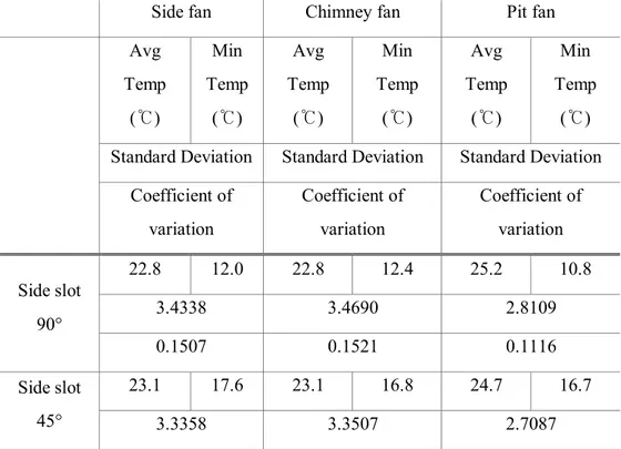
Table 11 CFD simulation results of temperature distribution in winter season
Side fan Chimney fan Pit fan Avg Temp ( )℃ Min Temp ( )℃ Avg Temp ( )℃ Min Temp ( )℃ Avg Temp ( )℃ Min Temp ( )℃ Standard Deviation Standard Deviation Standard Deviation
Coefficient of variation Coefficient of variation Coefficient of variation Side slot 90° 22.8 12.0 22.8 12.4 25.2 10.8 3.4338 3.4690 2.8109 0.1507 0.1521 0.1116 Side slot 45° 23.1 17.6 23.1 16.8 24.7 16.7 3.3358 3.3507 2.7087
0.1444 0.1453 0.1098 Side slot 30° 23.0 17.8 23.2 18.5 24.6 18.9 3.3206 3.3438 3.1569 0.1445 0.1440 0.1286 Ceiling hole 25.5 20.2 25.6 20.2 26.8 20.3 2.5285 2.5422 2.4783 0.0992 0.0994 0.0924 Ceiling slot 90° 24.5 18.2 24.4 17.9 26.2 19.9 3.2160 3.2060 2.4970 0.1314 0.1312 0.0954 Ceiling slot 45° 25.1 19.0 24.8 19.3 25.8 20.1 3.0250 3.0978 2.5581 0.1204 0.1251 0.0993 Duct (Equal) 23.2 19.2 23.6 19.5 24.6 19.9 2.5881 2.7089 2.6223 0.1116 0.1146 0.1065 Duct (Narrower) 23.9 19.7 24.0 19.8 25.0 19.9 2.6698 2.7071 2.6108 0.1117 0.1127 0.1045 Duct (Wider) 23.6 19.4 23.3 18.5 24.8 19.9 2.7318 2.7430 2.5798 0.1156 0.1178 0.1039
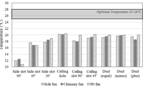
Fig. 13 Average temperature around the swine according to the ventilation system
Fig. 14 Minimum temperature around the swine according to the ventilation system
Table 11 shows the temperature near the swine according to the ventilation system. Low temperature is a serious problem for swine because they are sensitive to temperature changes. Therefore, it is important to understand the cause of cold
stress due to the ventilation structure.
Regardless of the inlet type, the total average temperature is found to be higher when the pit ventilation fan is used. When the ventilation fan of a chimney or a side wall is used, the air is exhausted from the single ventilation fan and the internal airflow is actively generated near the ventilation fan. However, in the case of the pit exhaust fan, since the pit is uniformly discharged through the fourteen holes in the pit, the inside of the pit is uniformly ventilated, and the internal flow velocity is low, so that a sudden temperature change can be prevented. Particularly, the coefficient of variation according to the ventilation fan is in the range of 0.11 ~ 0.15 for the sidewall fan and the chimney fan, but when the pit exhaust fan is used, the coefficient of variation is 0.09 ~ 0.10 and the uniformity is considerably improved. Fig. 22 show the minimum temperature of the swine room. It can be seen that any ventilation system can cause cold stress in winter season. Particularly, when the side slot is used as the inlet type, it reaches a minimum temperature of 10.8℃ to 17.8℃. In order to improve this, adjusting the angle of the side slot can prevent the occurrence of a minimum temperature to a certain extent, but still shows a temperature distribution that does not reach an optimal growth temperature of 25 to 28 ° C. Most farms have little ventilation to prevent this temperature problem. However, this method causes other problems like humidity and ammonia accumulation.
When the ceiling hole type is used, the air inflow through the small holes in the upper part of the swine room. Because the air is heated in the upper space, the inflow of cold air can be prevented. The minimum temperature around the swine was about 20.2 to 20.3℃ ℃ and the temperature distribution was uniform. In a similar way, when the air inflows through the ceiling slot, the inlet area is relatively wide and the inflow of cold air can increase. It is analyzed that it is effective to prevent low temperature stress than the case of using the side slot with a minimum temperature of 18.2℃ to 19.9℃. In addition, it was analyzed that the effect of temperature improvement was greater when the angle of the ceiling slot was
formed.
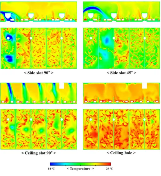
Fig. 15 The contour of temperature near the swine according inlet type
Fig. 24 below shows the number of swine groups divided from the corridor. The graph below shows the temperature distribution by swine group at each position according to the ventilation system. When the air inflow through the side slot, in group 1, the temperature was low at 21.9℃ and the coefficient of variation was 0.1507. In the case of forming an angle, air was induced to the upper part of the swine room, but it remained above the second group and still caused low temperature stress. The temperature was distributed as low as 22.4℃ and the
coefficient of variation was 0.1444 and the uniformity was still low. In the case of using the ceiling space, the temperature is uniformly distributed. This seems to be caused by the air slowly flowing down from the ceiling. When ducts were used, the coefficient of variation was about 0.11, and the temperature increase effect was lower than that of using ceiling space. Compared with the results of Wilson et al. (1977) and Song et al. (2002), the effect of temperature uniformity improvement was similar to that of duct installation.
Fig. 17 Minimum temperature around the swine according to the ventilation system
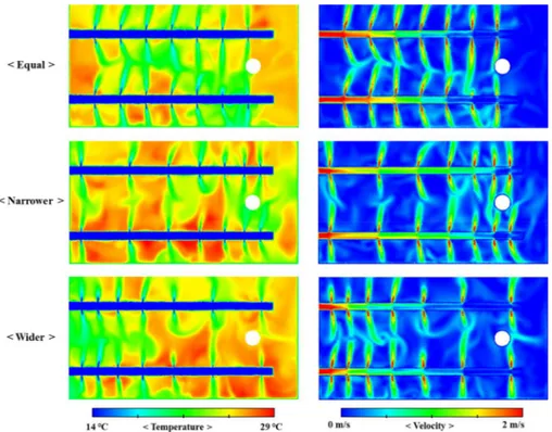
Fig. 18 Temperature and velocity distribution using duct inlet type according to hole interval
Looking at the temperature and velocity contours, the flow velocity difference between the exhausted air is large when the spacing of the holes is designed to be narrow. When the duct hole spacing was designed to be the equal, a relatively uniform flow rate was obtained. This is similar to the results of Song et al. (2002).
4.1.2. Analysis of humidity distribution with minimum
ventilation rate
Table 12 CFD simulation results of humidity distribution in winter season
Side fan Chimney fan Pit fan Avg AH Avg RH Avg AH Avg RH Avg AH Avg RH
(g/kg-da) (%) (g/kg-da) (%) (g/kg-da) (%) Side slot 90° 0.0142 81.8 0.0141 81.6 0.0193 96.5 Side slot 45° 0.0147 83.9 0.0149 84.8 0.0180 93.5 Side slot 30° 0.0144 82.7 0.0146 82.6 0.0182 95.0 Ceiling hole 0.0181 89.2 0.0181 88.7 0.0204 92.9 Ceiling slot 90° 0.0172 90.2 0.0172 90.6 0.0195 92.8 Ceiling slot 45° 0.0188 94.9 0.0176 90.8 0.0195 95.0 Duct (Equal) 0.0161 91.0 0.0162 89.3 0.0184 95.4 Duct (Narrower) 0.0169 91.7 0.0169 91.1 0.0183 93.2 Duct (Wider) 0.0157 86.5 0.0156 87.5 0.0188 96.5
Fig. 19 Relative humidity around the swine according to the ventilation system
The moisture produced in the swine room can be divided into the respiration and manure. In the case of the minimum ventilation in winter, the internal relative humidity was found to exceed the appropriate level of 60-80% in all results. The results are similar to the data measured by Jang et al. (1999) and Seo et al. (2008). The positions of side fan and chimney fan are very close. Since the fan diameter and ventilation rate are the same, there is no significant difference, and simulation results are similarly derived. On the other hand, when using a pit fan, the relative humidity was higher in all cases than in the other exhaust fans. This is because the relative humidity is influenced by the internal temperature. Also, a small-sized diameter of pit fan has a low velocity of air and is inefficient in removing moisture. In the case of using the side slot, since the outside air directly reaches the room, it is confirmed that the relative humidity is reduced to about 80%. However, it seems that it is not appropriate because this method is disadvantageous in terms of temperature.
Fig. 20 The contour of relative humidity near the swine according inlet type
4.1.3. Analysis of ammonia distribution with minimum
ventilation rate
Table 13 CFD simulation results of ammonia gas distribution in winter season
Side fan Chimney fan Pit fan Avg Ammoni a (ppm) Max Ammoni a (ppm) Avg Ammoni a (ppm) Max Ammoni a (ppm) Avg Ammoni a (ppm) Max Ammoni a (ppm) Side slot 90° 22.58 55.62 22.84 51.00 27.04 58.13
Side slot 45° 23.01 49.10 24.08 56.86 25.72 58.41 Side slot 30° 22.29 43.33 23.10 52.73 28.22 59.61 Ceiling hole 29.96 78.28 29.56 65.66 24.50 52.47 Ceiling slot 90° 26.07 68.72 26.73 69.69 23.28 57.04 Ceiling slot 45° 31.13 90.79 27.30 68.70 23.53 49.85 Duct (Equal) 27.57 53.08 27.57 57.66 26.86 57.09 Duct (Narrower ) 30.46 56.50 30.64 54.69 24.54 49.11 Duct (Wider) 24.77 51.38 25.00 46.54 27.00 62.39
system
Fig. 22 The contour of ammonia concentration near the swine according inlet type
If the ventilation rate is low and fresh air is not provided enough, the ammonia gas and odor inside the swine room may be excessive. Especially, in the case of ammonia gas, since it occurs in the lower manure, it first reaches the swine's nose. In addition, it is very difficult to predict the distribution of ammonia gas because measurement sensors and workers may be hard to notice. Prolonged exposure to an ammonia gas environment can reduce the appetite of the swine, lower feed
efficiency and reduce productivity. To improve this, it is most effective to remove the manure immediately. However, most farmers do not clean manure to save cost and time. In addition, the workers feel less need for cleaning manure because the ammonia concentration at the worker’s height is lower than at the swine’s height.
If only minimal ventilation was maintained during the winter, results were obtained above the proper ammonia concentration for all ventilation system (Fig. 29). Near the inlet, fresh air from the outside was flowed in, and relatively low ammonia concentration was distributed, but the concentration was high around the swine. Excessive gas concentration was found in the area where the air stagnated near the exhaust fan. The maximum concentration distribution was 90.79 ppm. The pit ventilation, in which air is sucked in the manure layer, showed a lower ammonia concentration. In order to remove ammonia gas, it was considered appropriate to increase the amount of ventilation or to suck air through the pit ventilation (Fig. 31).
Fig. 23 The contour of ammonia concentration near the swine according inlet type
If the outside air enters in a gap of the wall or fan shutter, the temperature problems may occur. The temperature distribution may be formed differently from the designed ventilation system. The ventilation is operated considering the inlet area. If the unnecessary area such as cracks occurs, it may be difficult to operate with the set ventilation rate. Also, cold air may flow in and cause low temperature stress. It is difficult to know the location and cause of this infiltration. A crack was formed at the top of the door to simulate the infiltration. The temperature of the swine group decreased by about 2.2 ° C. Because it can cause cold stress, the air tightness of the facility must be ensured. Also, if the gap between the exhaust fan and the shutter is not completely sealed, the infiltration may occur.
Fig. 24 The simulation results of the infiltration in cracks (door, shutter)
4.1.5. Analysis of temperature distribution with modified
ventilation rate
The following Table 14 shows the temperature distribution around the swine group when the ventilation rate is modified.
Table 14 CFD simulation results of temperature distribution using modified ventilation rate in winter season
Side fan Chimney fan Pit fan Avg Temp ( )℃ Min Temp ( )℃ Avg Temp ( )℃ Min Temp ( )℃ Avg Temp ( )℃ Min Temp ( )℃
Side slot 90° 20.1 11.1 18.7 9.2 21.2 11.0 Side slot 45° 20.9 14.8 20.2 14.5 21.5 15.3 Side slot 30° 20.8 13.7 20.8 13.9 21.9 14.6 Ceiling hole 22.3 17.8 22.3 16.9 24.2 18.9 Ceiling slot 90° 20.2 12.5 20.2 12.3 22.8 12.3 Ceiling slot 45° 20.6 16.0 20.6 15.8 22.2 16.3 Duct (Equal) 20.5 16.4 20.5 15.7 21.6 17.5 Duct (Narrower) 21.2 17.1 21.2 16.9 21.7 16.9 Duct (Wider) 20.4 16.9 20.5 16.7 21.4 17.0
Fig. 25 Temperature around the swine according to the ventilation using modified ventilation rate
When the ventilation rate was increased, the temperature in the swine room was all lowered. Increasing the ventilation rate to make the internal environment clean can cause internal low temperature problem. The pit fan and ceiling hole inlet type, which are the ventilation system to prevent the low temperature, have also problem when the ventilation rate was increased. The average temperature in the swine room was 24.2℃, and the lowest temperature was 18.9℃.