ICCAS2005 June 2-5, KINTEX, Gyeonggi-Do, Korea
1. INTRODUCTION
The PID(Proportional-Integral-Derivative) controller is widely used in the industry it can be implemented easily for a typical second order plant. This means that it can not obtain the required response characteristic of controller caused by changing plant. Thus it also makes the steady-state error occur and the response characteristic become for the worse.
The parameters of PID controller should be adapted complicatedly if a plant is various or the load is present. For solving the problem, many control techniques have been developed.
A major method is a hybrid Fuzzy-D controller. But, in case of using this method, we can not obtain characteristic of rapidly response and not achieved compensation on disturbance. Therefore, we will use compensator fuzzy controller a front Hybrid type fuzzy-D controller. Using this method, we would achieved rapidly response and robustness characteristics in application on step motor.
2. DESIGN OF CONTROLLER
2.1 Fuzzy PID controller
In this paper, we designed a combination of Fuzzy-PI controller and Fuzzy-D on a hybrid Fuzzy-PID controller. Generally, existing a hybrid Fuzzy-PID controller is linguistic type on output membership functions of fuzzy algorithms. A figure 1 is structure of general a hybrid Fuzzy-PID controller and figure 2 is membership functions of Fuzzy-PI and Fuzzy-D controller.
Fig. 1. A Structure of Hybrid Fuzzy-PID Controller
(a) Membership functions of Fuzzy-PI Controller
(b) Membership functions of Fuzzy-PD Controller Fig. 2. Hybrid Fuzzy-PID Controller (General Type)
A study on The Fuzzy Based PID Position controller for Step Motor Drives
Kim Seung Cheol*, Cho Yong Sung*, Park Jae Hyung*, Kang Shin Chul**, Bay Gyu Han***
* Dept. of Electronics Dong-A University, Hadan-dong, Saha-gu, 604-714, Busan Korea **Dept. of Computer Application Electricity, Namhae College, Namhae, Kyung Nam
***Korean Air Co. LTD
Phone : 82-051-200-6962, FAX : 82-051-200-7712 e-mail : [email protected]
(Tel : +82-2-200-6962; e-mail : [email protected] )
Abstract : In this paper, we applied step motor drive using a fuzzy logic control based on PID controller. A designed this
controller's purpose is improved robust and autonomous characteristic in which the variation of external load affects plant parameter. Therefore, in this paper, using a fuzzy logic control based on PID controller of two fuzzy-PI and fuzzy-D is obtained decremental overshoot and a special response quality.
Keywords: Fuzzy-PID controller, Fuzzy-D controller, Step motor, position controller
ICCAS2005 June 2-5, KINTEX, Gyeonggi-Do, Korea
An inference of Hybrid Fuzzy-PID controller is used Max-Min of Mamdani and defuzzification is used COG(Center of Gravity).
In a designed a hybrid Fuzzy-PID and a optimized Fuzzy-PID controller, a stage of Inference is used MAX-MIN operation of Mamdani and a defuzzification is used a COG(Center of Gravity)
2-2. Compensator Fuzzy
In this paper, Compensator fuzzy controller is designed by making general fuzzy logic control. Figure 3 is showed membership functions e, ce, u of compensator fuzzy controller. A fuzzy inference is used MAX-MIN of Mamdani, and defuzzification is used COG.
Figure 4 is showed a block diagram for simulation. Used parameters r’(k) and e’(k) is defined eq. (1).
'( ) ( ) '( ) '( ) ( ) '( ) r k r k u k e k e k u k = + = + (1) where, error e, e’(k)=r(k)-y(k) and rate change error ce(k)=e(k)-e(k-1) are input of compensator fuzzy controller, and u’(k) is output compensator fuzzy controller.
An inclusion compensator of dynamic characteristic is eq. (2). '( ) ( ) '( ) ( ) '( ) ( ) ( ) '( ) ( ) ( ) '( ) ( ) ( ) ( ) ( ) ( ) '( ) [ ( ), ( )] r k r k u k e k r k y k r k u k y k e k u k e k r k y k u k K v k u k F e k ce k = + = − = + − = + = − = + = (2)
where, F[e(k), ce(k)] is a nonlinear implemented using fuzzy logic. In following we describe how F[e(k), ce(k)] is implemented.
Associated with the function F[e(k), ce(k)] is a collection of linguistic values
L = [NB NM NS ZO PS PM PB]
And an associated collection of membership functions, M = [MNB MNM MNS Mzo MPS MPM MPB]
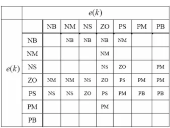
There rules for our compensator fuzzy are given in Table. 1
Fig. 3 Membership function.
Table.1 Rule table
Finally, as mentioned before, the actual control law for the compensator is given by the eq. (3)
'( ) '( 1) [ ( ), ( )]
u k =u k− +F e k ce k
(3)
Ш. SIMULATION
A common actuator in control systems is the step motor. It directly provides rotary motion and, coupled with wheels or drums and cables, can provide transitional motion.
The electric circuit of the armature and the free body diagram of the motor are shown in figure 5.
Fig. 3 Block Diagram of Step Motor
For figure 5, we will assume the following values for
the physical parameters in Table 2.
Where V voltage is, θ
i
is rotor speed of motor.
Table. 2 A specific of Step Motor
ICCAS2005 June 2-5, KINTEX, Gyeonggi-Do, Korea
The motor torque, T, is related to the armature current, i, by a constant factor Kt. The back emf, e, is related to the rotational velocity by the following eq. (4) and (5).
t T=k i (4) e e=K θ i (5)
In SI units (which we will use), Kt (armature constant) is equal to Ke (motor constant).
From the figure above we can write the following eq. (6) and (7) based on Newton's law combined with Kirchhoff's law.
Jθ+bθ=Ki i i i
(6) di L Ri V k dt+ = − θ i
(7)
Using Laplace Transforms, the above modeling eq. (8) and (9) can be expressed in terms of s.
( ) ( ) ( )
s Js+bθ s =KI s
(8) (Ls+R I s) ( )= −V Ksθ( )s (9)
By eliminating I(s) we can get the following open-loop transfer function in eq. (10)
where the rotational speed is the output and the voltage is the input. 2 ( )( ) K V Js b Ls R k θ = + + + i (10) In the state-space form, the eq. (10) can be expressed by choosing the rotational speed and electric current as the state variables and the voltage as an input. The output is chosen to be the rotational spee in eq. (11) and (12)
0 1 b K d j J V dt i K R i L J L θ θ ⎡− ⎤ ⎡ ⎤ ⎢ ⎥ ⎡ ⎤ ⎡ ⎤ ⎢ ⎥ ⎢ ⎥ ⎢ ⎥= ⎢ ⎥+⎢ ⎥ ⎢ ⎥ ⎢ ⎥ ⎢ ⎥ ⎣ ⎦ ⎢⎣− − ⎥⎦⎣ ⎦ ⎢ ⎥⎣ ⎦ i i (11)
[
1 0]
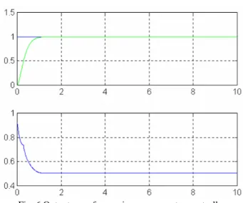
i θ θ= ⎡ ⎤⎢ ⎥ ⎢ ⎥ ⎣ ⎦ i i (12)Fig.6 is showed output waveform using compensator fuzzy controller are not include disturbance. In results, it is shown that slowly response in case of reference signal about 3 seconds.
Fig. 6 Output waveform using compensator controller. Fig.7 showed control signal of fuzzy-PI and fuzzy D and Fig.8 is include disturbance of output waveform.
Fig. 8 Output waveform of compensator controller with disturbance
Fig.9 control signal of fuzzy-PI and fuzzy-D
ICCAS2005 June 2-5, KINTEX, Gyeonggi-Do, Korea
Fig. 10 Output waveform(Not compensator controller)
Fig. 11 control signal of fuzzy-PI and fuzzy-D
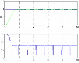
Fig. 12 Output waveform with disturbance(Not compensator controller)
Fig. 10 is showed output wave using Hybrid type fuzzy-PID controller and Fig. 12 is showed output waveform using Hybrid type fuzzy-PID controller include disturbance.
Fig. 13 Control signal of fuzzy-PI and fuzzy-D
5. CONCLUSION
In this paper, we designed Hybrid type fuzzy-PID controller with compensator fuzzy. Simulation results, we could not obtain rapidly response, but robustness in disturbance. The next study term, we will design of complementation controller and to observe the performance applied to real three phase DC Motor based on this simulation result.
REFERENCES
[1] Seul Jung and Richard C. Dorf, "Analytic PID Controller Design Technique for A Third Order System", Conference on Decision and Control 35th, Proc., Japan, 1996, pp. 2513-2517 [2] Hong Lian, Sng, Christopher H. Messom, Pik Kong, Yue, " Fuzzy Hybrid PID Controller of A steam Heated Dryer", IEEE International Fuzzy Systems Conference Proceedings, 1999, Korea, pp.1701-711
[3] Ghang-Ming Liaw, Faa-Jeng Lin, "A Robus Speed Controller for Induction Motor Drives", IEEE Transactions on Industrial Electronics, 1994, pp. 308-315
[4] K. Ogata, Modern Control Engineering, 2nd edition, Prentice Hall, 1990.
[5] C. C. Hang, K. J. Astrom, and W. K. Ho, "Refinements of the Ziegler-Nichols tuning formula, "Proc. IEE, Pt.D., vol. 138, pp. 111-118, 1991.
[6] R. C. Dorf and D. R. Miller, "A method for enhanced PID controller design", Journal of Robotics and Automation, vol. 6, pp. 41-47, 1991.
[7] R. C. Dorf and R. H. Bishop, Modern Control Systems, 7th edition, Addison Wesley, 1995.
[8] R. C. Dorf, S. Jung, J. Dawes, and L. Ng, "An s-plane analytic technique for lead-lag controller design", Proc. of American Control Conference, pp. 2227-2228, Seattle, June, 1995. [9] 박재형, 김승철, 조용성, 최부귀, “퍼지보상기와 퍼지 동조기를 이용한 PID 제어기의 Deadzone을 포함한 시스템제어 , 한국해양정보통신학회, Vol3, No. 2, pp. 403-410 1499