1. INTRODUCTION
The controller area network protocol (CAN) was developed to solve complex cable problem and reliability reduction in automotive industries [1-2]. This availability was built networks of high reliability, which could be applied to various industry environments [3-5].
A major advantage of using the CAN technology with respect to the other kinds of field-buses available is the wide choice of very cheap electronic components such as 82527 CAN controller of Intel Corporation. CAN applications are diffused widely because the convenience in application and a low cost which are very important factors in automation network construction. Also, because the CAN supports a priority system in a message transmission; it can satisfy an urgent communication which is needed in many industrial environments. And it is noted that components and communication boards are cheaper than the others network, a network administration method is convenient, and communication software can be executed easily.
Unlike the IEEE 802.3 standard access technique based CSMA/CD protocol[6], its medium access control mechanism ensures that when a collision occurs a non-destructive contention-based arbitration is initiated, which stops all the transmitting stations except the one which is sending the highest priority frame. The frames which are transmitted are not addressed to a specific destination, but they are considered as global objects and each of which is associated to a network-wide unique identifier. The CAN allocates absolute priorities to the messages or objects transmitted in network using ID’s. This mechanism is an effective method to adjust collisions in network.
But, when a collision occurs during a transmission, a high priority object can execute transmission continually, while a low priority object must wait until the network becomes idle. If the CAN network is overload, a low priority object can be delayed indefinitely by higher priority ones [7-9]. This situation can be avoided in periodic transmission networks by the round-robin arbitration, but can be a severe problem in independent and/or a-periodic transmission networks.
If a network is overload, a data transmission quantity is decreasing rapidly with the increase of data transmission collision. If this state is kept long, the network becomes groggy and non-transmission condition continues for a long time. This paper presents a mechanism that guarantees a fair transmission chance and reduces the delay time by the dynamic precedence queue. The precedence queue consists of several low priority objects which are required to be transmitted in a sequence. When the network is overload, by this dynamic precedence queue, a maximum tolerance delay time can be kept and ineffectiveness of assigning ID to each object can be removed out [10].
This precedence queue is not assigned statically but assigned dynamically considering the network conditions, so it can improve the transmission efficiency of the network. Each queue which has an independent transmission-sequence of data, has a relative priority in the network. This paper aims at the development of a mechanism that can guarantee the maximum allowable time-delay for the low priority objects by assigning the precedence queue and adjusting the priority dynamically based an extended CAN protocol.
The arbitration is realized in data link layer which is the middle layer among the three layers of the CAN. In the conventional CAN protocol, the identifier is assigned to an object statically, which can not satisfy the two requirements: a fair transmission chance and the maximum delay time. The ID assignment solves collision problems by only a static priority. In this paper, it is shown that the arbitration can be solved by filtering of input frames according to the identifier of each object and by redefining the identifier in the identifier field of CAN. By redefining this dynamic precedence queue (DPQ) with the usage of identifier field of extended CAN, each object can be transmitted according to a fair transmission sequence and within a maximum tolerance delay time. This modification is fully compatible with the services offered by standard MAC (Medium Access Control) sub-layer of CAN, thus the commercial components developed for the original protocol can be used here without any modification. This solution proposed in this paper also can be used for all CAN based-applications compatibly.
A Dynamic Precedence Queue Mechanism to Improve Transmission Efficiency
in CAN Networks
Jaemu Yun*, and Hoseek Choi
**,
and JangMyung Lee
**** Department of Electronics Engineering, Pusan National University, Pusan, Korea (Tel : +82-51-510-1696; E-mail: [email protected])
**Department of Electronics Engineering, Pusan National University, Pusan, Korea (Tel : +82-51-510-1696; E-mail: [email protected])
***Department of Electronics Engineering, Pusan National University, Pusan, Korea (Tel : +82-51-510-2378; E-mail: [email protected])
Abstract: This paper presents a dynamic precedence queue mechanism to resolve unexpected transmission delay of a lower
priority transaction in a CAN based system which keeps a fixed priority in data transactions. The mechanism is implemented in the upper sub-layer of the data link layer (DLL), which is fully compatible with the original medium access control layer protocol of CAN. Thus the mechanism can be implemented dynamically while the data transactions are going on without any hardware modification. The CAN protocol was originally developed to be used in the automotive industry and it was recently applied for a broader class of automated factories. Even though CAN is able to satisfy most of real-time requirements found in automated environments, it is not to enforce either a fair subdivision of the network bandwidth among the stations or a satisfactory distribution of the access delays in message transmissions. The proposed solution provides a superset of the CAN logical link layer control, which can coexist with the older CAN applications. Through the real experiments, effectiveness of the proposed mechanism is verified.
2. CAN ANALYSIS
2.1 A Basic CAN ProtocolCAN is based on a CSMA/CD channel access technique, and it uses a priority modification mechanism of transmission-reception message to resolve collision on a network. CAN protocol adopts a layered architecture which is based on the OSI reference model, even though it is not fully OSI compliant, and it consists of three layers among which the only application layer is usually open to implement the factory automation environment.
1. The Application Layer
: supports to access on a Network. 2. The Data Link Layer
: transforms the physical address to connect to the upper-low layer.
There are two sub-layers: LLC (Logical Link Control) sub-layer and MAC.
3. The Physical Layer
: transmits the bit streams to physical media.
This paper resolves transmission delay time problem using the data link layer, specifically using only LLC (Logical Link Control) sub-layer which is upper part of the data link layer.
2.2 Physical layer of CAN
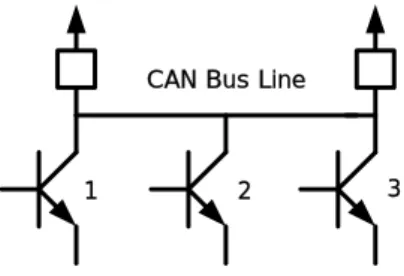
CAN network is based on a bus topology. The bus consists of two complementary logical values: dominant and recessive.
CAN Bus Line
1 2 3
Fig. 1 CAN physical layer.
The dominant value can be considered equivalent to the logical value 0, while the recessive value corresponds to the logical value 1. It is worth nothing that if several nodes transmit dominant and recessive bits at the same time, the resulting value of the bus will be dominant. In other word, the CAN behaves in a very similar way to the open-collector wirings in electronic circuits.
2.3 LLC sub-layer
The logical link layer is the upper part of data link layer; this layer is responsible for the frame acceptance filtering and the recovery management. The MAC sub-layer which is the lower part of the LLC sub-layer does not check the identifier of the received frames; it physically reads all of them. The identifier on CAN protocol does not contain the destination address of the message; instead it indicates only a kind of message.
The LLC sub-layer is responsible for the decision of ‘reception’ or ‘not reception’ of the received frames. The LLC
sub-layer also manages the retransmission of the frames which have been lost a contention or involved in transmission errors. The user does not have any information on the transaction in the middle, since the result of a transmission is not notified until it is completed successfully.
Fig. 2 CAN arbitration phase.
3. A DYNAMIC PRECEDENCE QUEUE
MECHANISM
CAN implicitly assigns a priority to each object exchanged on the network, which corresponds to an identifier of the object itself. Even though this mechanism enforces a deterministic arbitration which is able to resolve any conflict occurring when several nodes start to transmit at the same time, it is clearly unfair in many cases. If many nodes are connected to the network, nodes which are ranked by low priorities can continuously lose the transmission opportunity. Namely, if high priority objects transmit continuously, low priority objects can finally confront with dangerous situations due to missing important messages which are even though relatively less important than the high priority objects.
In accordance with, it is necessary to develop a mechanism which uses a relative priority scheme to guarantee the maximum allowable time delay for low priority nodes within the CAN protocol. A fair behavior, for an example, a round-robin policy, needs to be developed to guarantee all the objects with different priority levels can be successfully transmitted in a network. In this paper, it is shown that this kind of behavior can be obtained by slightly modifying the frame acceptance filtering function of the LLC sub-layer. In particular, by modifying the significance field of the identifier in the transmitted frame, a relative priority can be implemented within the CAN protocol. The resulting arbitration mechanism which has two levels of priority for the transmission is able to enforce a round-robin policy among the stations which want to transmit a message on the bus. Therefore in the modified transmission system, both of the standard ID of CAN protocol and ID of the DPQ protocol contribute to determine the priority of message transmission cooperatively. There is no change in the MAC level for this two level priority system. Therefore, with this modification, it is possible to reuse the same electronics components and circuits developed for the standard CAN protocol without any trouble.
3.1 DPQ principle
The basic idea of this CAN fairness control mechanism is to insert all the nodes which need to be transmitted over the shared medium into a global queue. As it is illustrated in Fig. 3, when a node C which needs to be transmitted, is continuously delayed, a queue is created for node C with other nodes which need to be transmitted with C. Several queues can be made independently. In this research, as an example,
two queues are set to show the effectiveness of the DPQ. a b c A B C D E F G C D E F G A B D E F G C d
Fig. 3 Generation of a precedence queue in DPQ mechanism.
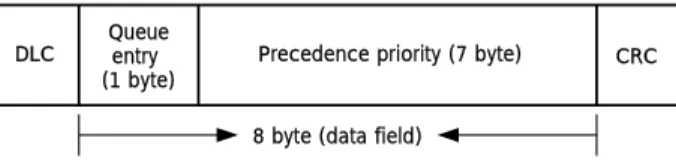
This distributed precedence queue protocol provides an opportunity to create precedence queue to all nodes on the network. And when several precedence queues exist concurrently, a priority can be assigned to each precedence queue. Therefore each precedence queue can be implemented independently. Fig. 5 illustrates the structure of data field for DPQ. In the figure, mode ID which is stored in the 11 bit standard ID field indicates the precedence queue order of each node. Whenever a node completes the transmission, it is moved to the end of the queue. At the moment, its precedence is lowered the minimum. The other nodes except a transmitted node proceed in the queue to fill up the space which has just been created by the precedent node. Using this dynamic round-robin policy, it is implemented to manage collision among the messages.
The queue is not physically stored in some specific location. Instead it is distributed among all the nodes on the network. Each node is responsible for storing and updating the queue. Namely, if it confronts with the maximum allowable delay time in the network, it creates a precedence queue. And then it changes its own priority dynamically to transmit preferentially with the related nodes. And the precedence queue becomes disjointed automatically as soon as the urgent situation is resolved.
As shown in Fig. 3, a network which has the nodes from A to G is selected as an example. If the node C builds up a queue, ID of nodes which hope to enter queue using a part of data frame can be transmit and designated to 7 by lower 7 bytes. At this moment, the precedence priority is set to the higher byte.
Then, through the filtering process, each node is decided to enter to the queue or not. After the transmission of the message C which is urgently requested, it will go the last position in the queue. And the other nodes will go to the upper queue by order. The remainder nodes which are transmitted are designated using the upper 1 byte of the data as shown in Fig. 3. The queue will be disjointed or maintained using the upper 1 byte in the Fig. 4 after the complete transmission of all nodes in the queue.
DLC
8 byte (data field)
CRC Queue
entry (1 byte)
Precedence priority (7 byte)
Fig. 4 Structure of a field for DPQ.
At this point, it is necessary to point out the difference between the priority and the precedence. Initially, the priority
is assigned to an object (it is a message) when it is connected to the network, which is also effective in designating the transmission order in the precedence queue. Since the priority is assigned to each object according to the importance and urgency, the precedence expresses transmission order in the queue. Both of the priority and the precedence are related to the deterministic resolution of collisions on the bus. Note that the priority is a static value, while the precedence that is not recognized to the user is a dynamic value.
The priority and the precedence of the message are defined by 18 bits ID and 11 bits ID, respectively, in the each transmission frame to implement an efficient method to resolve the collisions in a network.
3.2 DPQ Realization Method
The DPQ mechanism can be implemented with a simple modification of the basic format of CAN frames. The identifier field is used to designate the priority queue. Since the length of the conventional identifier field defined in the CAN standard is not long enough, the extended CAN format is adopted. 11bits base ID S S R I D E 18 bit ID EXT R T R r 0 r 1 DLC S O F
Fig. 5 Header format of the extended CAN frame. DPQ uses the first 11 bits of the identifier field for its control information, while the remaining lower 18 bits (ID ext.) are used to store extended identifier (EID) newly and dynamically. S O F t 0 t 1 P 8 bit PL S S R I D E 18 bit EID RT R r 0 r 1 DLC
Fig. 6 Header format of the DPQ frame.
To differentiate the DPQ mechanism from a standard CAN protocol, the first two bits (t0, t1) of the header frame must be set at the logical zeroes in Fig. 6. Therefore the objects in the DPQ always has the higher priority than the standard CAN based objects, and they are compatible in the same arbitration space.
The priority bit ‘P’ specifies whether the frame has to be transmitted as a high priority frame ‘P = 0’ or as a low priority frame ‘p = 1’. When ‘t1’ and ‘P’ are used to define queues virtually, the maximum 4 DPQ queues can be formed concurrently.
The next 8 bits represent the precedence level of the frame. That is, these 8 bits represent the transmission order in the DPQ. In summary, the DPQ mechanism proposed in this research utilizes the bits t0 and t1 to distinguish from the standard CAN mechanism, and sets the queue priority by the bit P, and determines the precedence pf objects in the queue by the following 8 bits in the header format.
4. SYSTEM ARCHITECTURE AND
EXPERIMENTS
To verify effectiveness of the proposed mechanism, an actuator ECU for throttle-body controller of vehicle and a portable inspection equipment ECU that sets sensor limit values and diagnosis the trouble of vehicle are established as
basic nodes. The total system consists of 10 nodes with eight virtual ECU’s which are used in many parts of the vehicle as the inhalation fuel ECU, the lighting ECU, the side-mirror ECU, the exhaust port ECU, etc.
Each node uses TMS320LF2407 with CAN module, it uses PCA82C251 with CAN transceiver. Each node is set 250Kbps transmission time. At the first experiment, the transmission period of total 10 nodes is set two states of 10ms and 2ms. When a transmission period is 10ms, there is not often occur collision. But when it is 2ms, there is often occur collision. Transmission message priority is arranged node 1(portable ECU) and node 2(main ECU) on each transmission period, this priority decrease gradually. When a transmission period is 2ms, node 8,9,10 occur a big transmission delay because of message collision on bus, it was applied DPQ mode at node 8,9,10 to resolve this problem.
Fig. 7 Experiment system organization.
At the second experiment, the system consists on two divisions. One uses 2ms transmission period, 7 nodes. The other uses 2ms transmission period, 10 nodes. Such as the first experiment, a transmission message priority is arranged in node 1, node2 order, it decrease gradually.
The node number increased to occur often collision when a node number is set 10 than when a node number is set 7, and such as the first experiment, DPQ mode is applied at node 8,9,10 when a transmission period is 2ms and a node number is 10.
Table 1 Identification Definition (ID) in experience 1.
node standard CAN DPQ
PORTABLE 11 1 0000 0001 11 1 0000 0001 MAIN ECU 11 1 0000 0010 11 1 0000 0010 3 11 1 0000 0011 11 1 0000 0011 4 11 1 0000 0100 11 1 0000 0100 5 11 1 0000 0101 11 1 0000 0101 6 11 1 0000 0110 11 1 0000 0110 7 11 1 0000 0111 11 1 0000 0111 8 11 1 0000 1000 00 1 1111 1101 9 11 1 0000 1001 00 1 1111 1110 10 11 1 0000 1010 00 1 1111 1111
Table 2 Identification Definition (ID) in experience 2.
node standard CAN DPQ
PORTABLE 11 1 0000 0001 11 1 0000 0001 MAIN ECU 11 1 0000 0010 11 1 0000 0010 3 11 1 0000 0011 11 1 0000 0011 4 11 1 0000 0100 11 1 0000 0100 5 11 1 0000 0101 11 1 0000 0101 6 11 1 0000 0110 11 1 0000 0110 7 11 1 0000 0111 11 1 0000 0111 8 00 1 1111 1101 9 00 1 1111 1110 10 00 1 1111 1111
Fig. 8 shows the transmission delay time of the node 1. From number 1 to number 50, Y axis values show a transmission delay time when a transmission period is 10ms. And from number 51 to number 100, values show a transmission delay time when transmission period is 2ms. And from number 101 to number 150, values show when DPQ mode is applied. 0 500 1000 1500 2000 2500 3000 1 12 23 34 45 56 67 78 89 100 111 122 133 144 number usec
Fig. 8 Transmission delay time of node 1 in experiment 1. At a result of the Fig. 8, we can know that node 1 increase a delay time for switching to transmit frequently when a transmission period is 2ms than when transmission period is 10ms. And it occurs additional delay time to consideration of node 8,9,10 on DPQ mode.
At the Fig. 9, in the case of node 8, the state which a transmission period is 2ms, occurs a long delay time to low priority than others nodes. To overcome this case, we can verify that a transmission chance is guaranteed and delay time is advanced outstandingly, when DPQ mode is applied instead of exchange priority permanently to see Fig. 10.
In the experiment 2 case of the Fig. 11, the graph shows a transmission delay time. From number 1 to number 50, Y axis values shows a transmission delay time of node 1 of the highest priority when transmission period is 2ms. And from number 51 to number 100, values shows that when a node number is 10. From number 101 to number 150, values show when DPQ mode is applied.
0 500 1000 1500 2000 2500 3000 1 11 21 31 41 51 61 71 81 91 101 111 121 131 141 number usec
Fig. 9 Transmission delay time of node 8 in experiment 1.
0 200 400 600 800 1000 1200 1400 us ec 1 2 3 4 5 6 7 8 9 10 Node
Fig. 10 Average transmission delay time of DPQ mode in experiment 1.
The extender a node number, it can know that a transmission delay time of the highest priority node increases progressively. It can be verified that a transmission time of the highest priority node increase progressively, considering transmission of low priority node according to DPQ mode.
0 500 1000 1500 2000 2500 3000 1 10 19 28 37 46 55 64 73 82 91 100 109 118 127 136 145 nu mbe r us ec
Fig. 11 Transmission delay time of node 1 in experiment 2.
0 500 1000 1500 2000 2500 3000 1 8 15 22 29 36 43 50 57 64 71 78 85 92 99 number usec
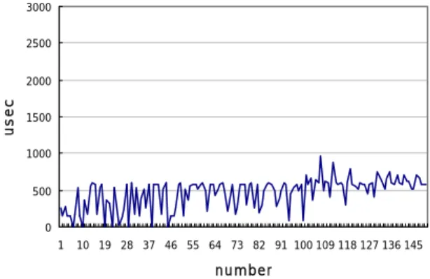
Fig. 12 Transmission delay time of node 8 in experiment 2. And the Fig. 12 shows a transmission delay time of the node 8 in experiment 2. From number 1 to number 50, values show a transmission delay time when a node number is 10. And from number 51 to number 100, values show a delay time when DPQ mode is applied, it can be known that transmission delay decrease signally.
0 200 400 600 800 1000 1200 us e c 1 2 3 4 5 6 7 8 9 10 N o d e
Fig. 13 Average transmission delay time of DPQ mode in experiment 2.
Fig. 13 shows an average delay time of nodes when DPQ mode is applied, it can be verified that node 8,9,10 applied DPQ mode short extremely transmission delay time. But application of DPQ mode is disorganized promptly dynamically if tolerance maximums delay time problem is resolved, then it must notice that transmission based on a original priority is accomplished.
6. CONCLUSION
This paper proposes a DPQ mechanism to remove out the ineffectiveness in a fixed priority mechanism and to arbitrate collisions in the networks using a standard CAN protocol. Effectiveness of the proposed mechanism is established and proved through real experiments with two different states. By the first experiment, it is shown that a transmission of the low priority node does not excess the maximum tolerance delay time using the DPQ mode. The experiment was performed in the environment of frequent collisions at the transmission, and of short transmission periods for the nodes with different priorities. In the second experiment, it is demonstrated that the DPQ mode effectively manages the frequent collisions not to increase the transmission delay time of the low priority object. It is clearly demonstrated that without the DPQ mode, the low
priority objects are suffering from the long time delay with the increase of objects in the network. In the future research, it is necessary to develop an optimal algorithm which efficiently manages the time delay of each object by applying DPQ mechanism dynamically. Also the compatibility of the developed algorithm with the conventional CAN based system needs to be verified to be an applicable mechanism.
ACKNOWLEDGMENTS
This work was supported by "Research Center for Logistics Information Technology (LIT)" hosted by the Ministry of Education & Human Resources Development in Korea.
REFERENCES
[1] International Standard Organization, “Road - vehicles Interchange of digital information - Controller area network for high-speed communication” ISO 11898, November, 1993.
[2] International Standard Organization, “Road - vehicles Interchange of digital information - Controller area network for high-speed communication” Draft Amendment, ISO 11898:1993/DAM 1, February, 1994. [3] CAN in AUTOMATION International Users and
Manufacturers Group e. V. “CAN Application Layer (CAL)”, CiA/DS201-CiA/DS205, CiA/DS207.` [4] Jin W. Park, Dong K. No, Jae H. Park, Hwa R. Hur, Jang
M. Lee, “Implementation of a Mobile Robot with Distributed Control Structure using CAN” Autumn Combination Conference . pp 251-255.1999.
[5] Sung S. Hong, “A distributed real time control systems,” CASE Technical Special: Real-Time Control System (3), ICASE, 1, 1998.
[6] IEEE Standards for Local Area Networks, “Carrier Sense Multiple Access with Collision Detection (CSMA/CD) Access Method and Physical Layer Specifications”, ANSI/IEEE Std 802.3- ISO/DIS 8802/3, 1985.
[7] K. Tindell and A. Burns and A. Wellings, “Calculating Controller Area Network (CAN) Message Response Times”, in Proc. 1994 IFAC Workshop on Distributed
Computer Control Systems, Toledo, Spain, September,
1994.
[8] K. Tindell and A. Burns, “Guaranteeing Message Latencies on Control Area Network (CAN)”, in Proc. 1
st International CAN Conference, Mainz, Germany,
September, 1994.
[9] K. Tendell, A. Burns and A. Wellings, “Analysis of Hard Real-Time Communications”, Report YCS 222,
Department of Computer Science, University of York ,
to appear in Real-Time Systems, 1994.
[10] “SDS-Smart distributed system specification” Hineysell Inc., Micro Switch Division, Phoenix, AZ, GS 052-103/104/1-5/106/107/1-8.