ICCAS2005 June 2-5, KINTEX, Gyeonggi-Do, Korea
Development of a Intelligent Welding Carriage for Automation of Curved Block
H.B. Choi∗, J.H. Moon∗∗, W.R. Jun∗, and S.H. Kim∗Automation Research Part, SAMSUNG HEAVY INDUSTRIES, Seoul 123-456, Korea (Tel: +82-55-630-6281; Fax: +82-55-630-5562; Email:{hb7.choi,biogreen.jun,sh3.kim}@samsung.com)
∗∗Welding Research Part, SAMSUNG HEAVY INDUSTRIES, Seoul 123-456, Korea (Tel: +82-55-630-6226; Fax: +82-55-630-5562; Email:[email protected])
Abstract: This paper presents a novel Intelligent-Welding-Carriage (IWC) for automation of curved block in shipbuilding.
The curved block is usually used in both front and back side of the ship. In curved block root gap is big, 1∼7 [mm] and inclination, 0∼30 [deg]. Since available conventional carriage type is limited to use below root gap of 3 [mm], only manual welding is employed in curved block. To adopt an IWC in curved block, it requires control of the welding conditions, i.e., voltage, current and travel speed, with respect to root gap and inclination to achieve good welding quality. In this paper, an IWC is developed for automization of welding operation to accommodate gap and inclination. Kinematics model and dynamics using Lagrangian formulation of the manipulator is introduced. IWC utilizes a database to perform accurate welding. The database is programmed based on numerous experimental test results with respect to gap, inclination, material, travel speed, weaving condition, voltage, and current. Finally, experimental result using PID control is addressed for verify the trajectory tracking accuracy of end-effector.
Keywords: Welding, Carriage, Curved-Block, Shipbuilding, Automization
————————————————————————————————————————————————
1. Introduction
Recently, due to the shortage and aging of experienced man-power, the development of robot-controlled automatic arc welding been encouraged. Despite the increasing importance of automation, i.e., welding, blasting, painting and coating activities as well as the increasing difficulties in finding work-ers, no substantial steps have been taken towards the weld-ing automation. Many efforts for automation in shipbuild-ing have been applied almost exclusively in subassembly line [1][2][3][4].
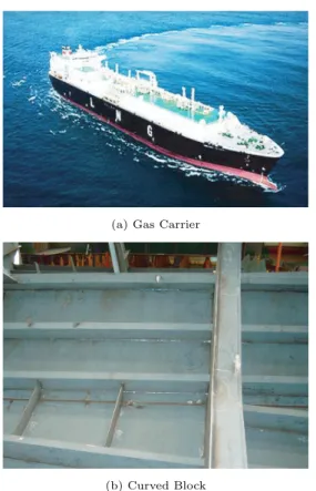
In the shipbuilding, welding automation in a factory devel-oped drastically. On the other hand, welding in a curved block still depends on by manual operation mainly. Espe-cially, welding of a curved block is done by a skilled welder manually, because it is difficult to weld it automatically in the curved block as shown in Figure 1.
It is important to reduce production time, and costs by rais-ing productivity in industrial work. Moreover, reduction of welding construction costs is strongly required and there-fore, to cope with this demand in the field of arc welding, there has been a significant trend of increasing welding ef-ficiency, improving at the same time the quality of welds. Automated welding system always aims at higher efficiency production, regarding the welding processes as core axes, then robot programming systems, seam tracking and adap-tive control, welding robots and automated machines, are comprised as the basic systems.
Y. Sugitani developed lattice welding robot [5]. This robots consists of a high speed rotating arc welding torch, 2-axis slide blocks and a self-driven carriage. A. Aoki suggested a multi-purpose welding robot system [6]. It is provided with portable and modularized system component equip-ment. D.Y. Lee, et. al. proposed a new system for auto-matic transfer of the LNGC (Liquefied Natural Gas Carrier)
(a) Gas Carrier
(b) Curved Block
Fig. 1. LNGC and Curved Block
membrane plasma welding-machine [7].
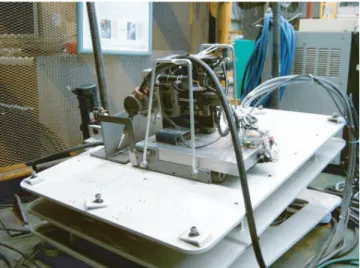
In this paper, for the purpose of high efficiency welding of the curved block, we developed an Intelligent Welding Car-riage System. It is the sensor-aided and self-driven welding robot and its purpose is fully automatic welding of the curved block.
Fig. 2. Intelligent Welding Carriage System
2. System Configuration
In this study, we consider an IWC system that consists of a four-linked manipulator mounted at the center point of a four-wheeled mobile-platform. The basic concept of IWC is described Figure 2.
2.1. Motors
The IWC employs DC type motors embodying encoders. The maximum torque, rated speed and assigned power rat-ing are 26.3 [mNm], 11000 [rpm] and 20 [W], respectively.
2.2. Motion Controller
For the control of IWC motion controller developed by SHI Mechatronics Research Team is adopted [7]. Using this troller 8 axes can be controlled. Controller is consist of con-trollers, power supplies for sensor and motors.
PID control is just used for IWC. The controller decodes the feedback signal of the encoder with the sampling of regular interval, based on the programmed position and speed of the host computer.
2.3. Sensors
Laser Vision Sensor(LVS) is used for seam tracking and checking gap. Limit sensors are applied to each axis to check the axes end. Especially, x-axis, driving direction, the proximity sensor is used. Moreover, inclinometer CXTA02, Crossbow, is employed for sensing the tilting angle of IWC. The tilting sensor have dual axis and angular range is
± 75 [deg].
2.4. Motion Table
For the welding test as in curved block, Motion Table is developed. Using this table, welding test can be achieved
±35 [deg]. And magnetic is set on the bottom side to prevent
the falling of IWC.
3. Kinematics of ICS
In this section, the inverse kinematics of ICS is considered. This chapter will be devoted to the kinematics of the IWC which means studying geometrically the motion of the IWC links. Kinematics deals with the aspects of motion without regard to the forces and torques that cause it or result from the motion [9]. Inverse kinematics is to find all possible
Σ
0,1
0,1
Σ
4
Σ
3
Σ
2
Σ
b
x
0,1x
2x
3x
4z
0,1y
0,1z
2y
2y
3z
3y
4z
4L
2L
1d
1L
4d
2L
3L
5L
6d
3Fig. 3. Design parameters Table 1. Link parameters of the IWC
i αi−1[deg] ai−1 [mm] di [mm] ai[deg]
1 0 0 0 θ1
2 90 L1 d2 0
3 -90 L3 d3 -90
4 -90 L5 L6 θ4
sets of actuated joint variables and their corresponding time derivatives which will bring the travelling plate to the set of desired positions and orientations, On the other hand, forward kinematics is to find all possible sets of travelling plate positions and orientations.
Typically, as the number of kinematic chains increases, the forward kinematics becomes more difficult. It is well known that in the case of a 6-DOF conventional serial robot the for-ward kinematics is relatively simple, while the inverse kine-matics is difficult. To express the positions and orientations of the IWC, a assignment of a coordinate frame will be ex-plained.
3.1. Inverse Kinematics
The prototype of the Intelligent welding system is illustrated in Figure 3. The link parameters corresponding to this place-ment of link frames are shown in Table 1. The link trans-formations can be defined as follows: Finally, we obtain the product of all four link transforms as follows:
0T 4=0T11T22T33T4 = 2 6 6 6 4 Cθ4Sθ1 −Sθ1Sθ4 −Cθ1 px −Cθ1Cθ4 Cθ1Sθ4 −Sθ1 py −Sθ4 −Cθ4 0 pz 0 0 0 1 3 7 7 7 5 (1)
where,
px= Cθ1L1+ Sθ1L2+ Cθ1L3+ Sθ2L5− Cθ1L6 py= −Sθ1L1− Cθ1L2− Sθ1L3− Cθ2L5+ Sθ1L6 pz= L4
with, L1, L3, L5, L6, and d3 are 100 [mm], 50 [mm],
120 [mm], 50 [mm], and 50 [mm], respectively. 4. Dynamics of ICS
We assume that the mobile-platform and the manipulator move at low speed because the welding velocity is just about 7.5 [mm/s] hence we ignore the inertia and the slipping be-tween the wheels and the floor, so we only consider the kine-matic representation for the mobile manipulator.
4.1. Notations
The terminologies which are used in this paper are repre-sented as follows:
r radius of the wheel
θi angle of ith revolute joint
˙θi angular velocity of ith revolute joint di distance of ith prismatic joint
˙di velocity of ith prismatic joint mb the mass of the driving wheel
mw the mass of the platform without the driving wheels mi the mass of the ith link of the manipulator
Ip the moment of inertia of the platform without driving wheels
Iw the moment of inertia of the driving wheel about the wheel axis
Iixx the moment of inertia of the ith link about the X-axis Iiyy the moment of inertia of the ith link about the Y-axis Iizz the moment of inertia of the ith link about the Z-axis
4.2. Lagrangian Formulation
In contrast to kinematics which deals with the geometry and time-dependent aspects of motion without considering the forces causing motion, dynamics based on kinematics in-cludes the effect of the inertia forces. Dynamics is one of a very complicated subject. Typically, dynamics is described in terms of the time rate of change of a given travelling plate’s trajectory in relation to the joint torque exerted by the ac-tuators. The actuating torque would depend not only on a given trajectory but also on the mass properties of the links, and external forces. There are two types of dynami-cal analysis problems namely forward dynamics and inverse dynamics.
Dynamics are useful for computer simulation, the design of suitable control equations, and the evaluation of the kine-matic design. For the real time control, the computational efficiency of inverse dynamics is one of the important issues. As an alternative methods for dynamics analysis, such as the Newton-Euler method, the Lagrangian methods, and the principle of virtual work can be applied. In this section, the Dynamics of ICS is addressed using Lagrangian formulation. The Lagrange equation of motion for the mobile manipulator
is given as
τ = ddt∂L∂ ˙q − ∂L∂q (2)
where
q =[θ1 θ2 θ3 θ4 θw]T
τ =[τ1 τ2 τ3 τ4 τw]T
Here, θ1, θ2, θ3 and θ4 are the angular displacement of the
joint and θ1, θ2, θ3and θ4are the torques action on the joint
and wheel axis generated by actuators. Equation 3 can be expressed as follows:
τ = ddt∂ ˙q∂k− ∂k∂q + ∂u∂q, (3)
where, k is the kinetic energy of the ith link and u is the potential energy of the ith link.
In this paper since the velocity of the mobile platform is as slow as the inertia can be ignored, we just consider that the Lagrangian is reduced to the kinetic energy K.
L = kp+ km− up (4)
where kp, km, and um are the kinetic energies of the mobile platform and the manipulator, and potential energy of ma-nipulator, respectively. These can be expressed as follows:
kp=1 2(mb+ mw)( b˙x2 0+b˙y02) + Iwbω2w km=k1+ k2+ k3+ k4 =14hA ˙d2 2+ B ˙L24+ C ˙d2˙θ1+ A ˙d22˙θ12+ Dd2˙θ12 + (E + F Cθ4+ GC2θ4) ˙θ12− HCθ4˙L4˙θ4 +JSθ4˙θ1˙θ4+ 2G ˙θ24 i +12(I1zz+ I2yy+ Izz) ˙θ12 + 12(I4xxSθ24+ I4yyCθ24+ I4zz˙θ24) up= − m3g(L4+ L4max) − m4gL7(Sθ4+ 1) (5) where, A =2m2 B =2(m2+ m3+ m4) C =4(−L1+ L3)m2 D =4L2m2 E =(2L2 1+ 2L22)m1+ (2L21+ 2L22− 4L1L3 + 2L23)m2 + (2L21+ 2L22+ 4L1L3+ 2L23+ 4L2L5+ 2L25 − 4L1L6− 4L3L6+ 2L26)m3+ (2L21+ 2L22+ 4L1L3 + 2L2 3+ 4L2L5+ 2L25− 4L1L6− 4L3L6+ 2L26+ L27)m4 F =4(L2+ L5)L7m4 G =L2 7m4 H =4L7m4 J =4(L1+ L3− L6)L7m4
Dynamic equation of motion for the mobile manipulator is given in the vector form as follows:
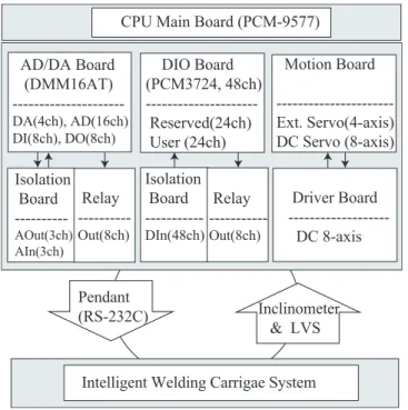
CPU Main Board (PCM-9577) Motion Board ---Ext. Servo(4-axis) DC Servo (8-axis) AD/DA Board (DMM16AT) ---DA(4ch), AD(16ch) DI(8ch), DO(8ch) DIO Board (PCM3724, 48ch) Reserved(24ch) User (24ch) Driver Board DC 8-axis Isolation Board --- AOut(3ch) AIn(3ch) Relay ---Out(8ch) Isolation Board --- DIn(48ch) Relay ---Out(8ch) Pendant (RS-232C) Inclinometer & LVS Intelligent Welding Carrigae System
Fig. 4. System Configuration
where, M (q), N (q), and G(q) are the 5×5 inertia matrix which is the function of the angular displacements for the joints and wheels, the 5×1 torque vector due to coriolis and centrifugal terms, and is an 5×1 vector of gravity terms.
5. Experimental Result
In this section, the dynamics of ICS is considered. The ve-locity of the end-effector must keep up the welding veve-locity in the whole welding process.
For real-time controll LINUX is used for IWC. RT-LINUX was developed by Finite State Machine, Inc. It works by patching the standard Linux kernel with the real-time plug-in. The real-time plug-in is in itself a small predictable operating system. It have its own scheduler and interrupt
Trajectory Generation
PID Controller
Digital Filter/Encourage Noise Immunity
Quadrature Decoder Up/Down Counter Motor / Encoder PWM Control Signal 1/Ts Kp, Ki, Kd
Fig. 5. Block diagram of PD control
0 1 2 3 4 5 0 200 400 Gap [mm] Time[s] C D (a) Stiffener 1.5 2 2.5 3 3.5 4 4.5 0 1 2 3 4 5 6 7 8 9 Gap [mm] Time[s] Reference 1st test 2nd test 3rd test 4th test fitting-1 fitting-2 (b) Angle
Fig. 6. Comparision of gap data
45 50 55 0 200 400 600 PWM Time[s] Reference Filtered (a) X axis 45 50 55 0 500 1000 1500 2000 2500 PWM Time[s] Reference Filtered (b) Y axis
Fig. 7. Comparision of x-y inclinations
(a) Start point (b) End point
Fig. 8. Rotating of the end effector
handlers. To compare the performance characteristic such as trajectory and control, the PID control methods are applied as shown Figure 5. The data from the LVS are not suit-able to use directly. Therefore, in this system we adopted the Kalman filter as shown Figure 6 (a). In case of An-gle the end is rounded. Since it caused the gap error, less productivity with poor quality of weld and high repair rate. To reduce this problem, the gap resolution test is achieved shown Figure 6 (b).
The torch angle should be changed as the slop is increasing. However, as shown Figure 7 (a), (b) the inclination data is not linear. Therefore the Kalman filter is also adopted to minimize the difference of inclination data.
To verify trajectory tracking accuracry of the torch end, the experimentation accomplished as shown Figure 8 (a), (b). The experimental results are shown in Figure 9 (a) (d). To-tal time, Sampling time, starting point, and end point are 70 [s], 20 [ms], (-5,0,0) and (25,0,0), respectively. In the ex-periment, the control gains, Kpand Kdwere set to 500 [s−1] and 2.5, respectively. For this experimentation the total 5-DOF is reduced to 3-5-DOF. Therefore the inverse kinematics of manipulator could be solved as 2-DOF problem (see Ap-pendix). In each figure, (a), (b), (c), and (d) represent the desired traveling plate trajectory with the current traveling
-5 5 15 25 0 30 60 x [mm] Time[s] Current Reference (a) x -1 0 1 0 30 60 y [mm] Time[s] Current Reference (b) y -1 0 1 0 30 60 Z [mm] Time[s] Current Reference (a) z -1 0 1 -5 5 15 25 z [mm] x[mm] Current Reference (b) x-z
Fig. 9. Comparision of x-y inclinations plate trajectory of x, y, z, and x−z, respectively.
In the result of PID control, there is a considerable delay in position (Figure 9) (a). The trajectory traking error is becoming greater at the end point than start point. This error could be reduced by adopting PD + feed forward, etc.
6. Conclusion
In this paper, we presented a novel Intelligent-Welding-Carriage (IWC) for automation of curved block. The IWC is developed for automization of welding operation to accom-modate gap and inclination. Kinematic model of the manip-ulator is introduced. Kinematics and Dynamics of IWC are addressed in order to adopt trajectory tracking control. IWC can utilize a database to perform accurate welding. The database is programmed based on numerous experimental test results with respect to gap, inclination, material, travel speed, weaving condition, voltage, and current. This exper-imental results demonstrated that the IWC is promising as a good welding mechanism.
Appendix
The inverse kinematics of IWC as 2-DOF can be calculated as follows:
[0T
1]−10T3=1T22T3. (7)
Equating the (1,4) elements from both sides of Equation 7, we have
Cθ1px+ Sθ1py= l1+ l2 (8)
To solve an equation of this form, we make the trigonometric substitutions
px= ρSφ, py= ρCφ (9) where
ρ =qp2x+ p2y, φ = Atan2(px, py)
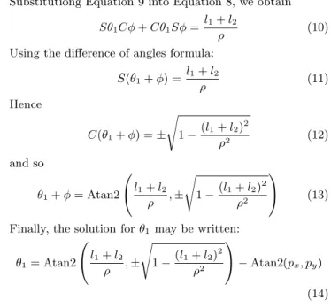
Substitutiong Equation 9 into Equation 8, we obtain
Sθ1Cφ + Cθ1Sφ = l1+ lρ 2 (10)
Using the difference of angles formula:
S(θ1+ φ) = l1+ lρ 2 (11) Hence C(θ1+ φ) = ± s 1 −(l1+ lρ22)2 (12) and so θ1+ φ = Atan2 0 @ l1+ l2 ρ , ± s 1 −(l1+ lρ22)2 1 A (13) Finally, the solution for θ1 may be written:
θ1= Atan2 0 @ l1+ l2 ρ , ± s 1 −(l1+ lρ22)2 1 A − Atan2(px, py) (14) Now tha θ1 is known, the left-hand side of Equation 7 is
known. If we equate the (1,4) elements from both sides of Equation 7, we obtain
−Sθ1px+ Cθ1py= −Cθ2l3− d (15)
From Equation 15,
d = Sθ1px− Cθ1py− Cθ2l3 (16)
References
[1] T. Miyazaki, Y. Nakashima and et. al, “NC Painting Robot for Shipbuilding”, Proc. ICCAS’99, 1999 [2] Kim J.H., Do G.S. and Yoon J.W., “Information
Man-agement for Automation of Sub-assembly Welding Line in Shipbuilding”, 2nd Asian Control Conference, 1997 [3] T.T. Phan, T.L. Chung, M.D. Ngo, H.K. Kim, and S.B.
Kim, “Decentralized Control Design for Welding Mobile Manipulator”, Journal of Mechanical Science and
Tech-nology, vol. 19, no. 3, pp. 756–767, 2005
[4] Yoo, W.S., Kim, J.D. and Na, S.J., “A Study on a Mobile-Platform Manipulator Welding System for Hor-izontal Fillet Joints”, Trans, Mechatronics, vol. 11, pp. 853–868, 2001
[5] Y. Sugitani, N. Tamaoki and M. Murayama, “Develop-ment of Lattice Welding Robot”, Technical Commision
of Welding Processes, Japan Welding Society, pp. II–
190, 1996
[6] A. Aoki, T. Iizuka, H. Mizuno, S. Yonemoto, and K. Yasuhara, “Multi-purpose Welding System Using Small Portable Robot”, Welding Guide Book V, pp. II–214, 2004
[7] D.Y. Lee, J.H. Jung, S.H. Han, Y.J. Lee, and Y.J. Park, “Spider Robot-Automatic Transfer System of the Plasma Welding Machine for LNGC Membrane Sheet”,
ICCAS 2004 Int. Conf. on Control, Automation and Systems, 2004
[8] J.J Craig, “Introduction to robotics Mechanics and
Con-trol”, Addison-Wesley, 1989