2335
Abstract
– This paper proposes an optimal damping control algorithm of the DTI (Direct Two-level Inverter) to miniaturize and reduce the weight of auxiliary power supply for railway vehicles. The conventional auxiliary power supply for railway vehicles uses a DC-DC converter to maintain the inverter input power from the line voltage smoothly. The proposed topology does not use a DC- DC converter for reducing of manufacturing and maintenance costs. It also proposes a DTI topology removed damping resistors that generate ground signal noise in a certain period. At this time, a resonance phenomenon of DC-link voltage occurs due to variation of the inductive load, and a method of controlling the resonance phenomenon of DC-link voltage is required. In order to suppress the resonance phenomenon of the DC-link voltage, at a point before resonance occurs, this paper introduces an algorithm to suppress the resonance phenomenon of DC-link voltage by compensating the resonance component of the q axis voltage of the synchronous reference frame. The proposed algorithm verifies the effect through simulation and experiment.Keywords:
Static inverter, SIV, Damping control, Direct tow-level inverter, DC-link voltage, Railway vehicle, Bandpass filter, Voltage resonance, Damping control.1. Introduction
Recently, using of public transportation is getting increased, it requires improvement of the railway vehicles technologies. Also gradually, as the load becomes larger and more diversified with developments of power semi-conductor technology and power electronics technology, a new SIV(Static Inverter) method is being developed for an auxiliary power supply device which pursue mini-aturization, lightweight, low noise and improved reliability [1].
Generally, the electrical power of the railway vehicle is being supplied through the pantograph mounted on the upper part and it supplies to the auxiliary power unit and the propulsion control system. An auxiliary power supply unit of a railway vehicle using a stationary inverter receives electric power from overhead wire voltage that varies widely under DC 1500V standard, creates a commercial power supply of a constant voltage and frequency, and supplies air conditioning equipment, passenger compartment such as a control power supply. [2-5].
The conventional auxiliary power supplies for railway vehicles received the line voltage and formed the DC-link voltage of the inverter through the DC-DC converter. However, this topology has the disadvantage that the cost
of fabrication and maintenance is caused by the DC-DC converter. To solve this problem, there is a topology in which the DC- DC converter possible can be removed. However, due to inductive loads such as air conditioners and air compressors, the resonance phenomenon occurs in the DC-link voltage. A topology using a damping resistor for power source of DC link voltage can solve this problem. This topology using the damping resistance, the DC-DC converter is eliminated, there is a disadvantage that the damping resistance communication noise is generated due to the influence of the current flowing through the line. This disadvantage has the problem of eliminating the damping resistance. Because there is a track occupancy that capture signals in orbit turn from blue to red and the vehicle is engaged in emergency braking before a train enters a certain station and stops [6-9].
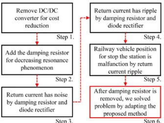
Fig. 1 shows the procedure to solve the problem from conventional auxiliary power supply problem. This paper approached the conventional method problem by order Fig. 1. In addition, this paper applied the proposed method for solving the problem.
This paper proposes an optimal control algorithm of DTI topology for miniaturization and weight lightening of the auxiliary power supply for railway vehicles. The algorithm proposes to suppress the resonance phenomenon of the DC-link voltage by eliminating the damping resistor which causes communication failure in a certain period. At the point of resonance of the DC-link voltage, it suppresses the resonance phenomenon of the DC-link voltage by compensating the component for resonance in the q axis
† Corresponding Author: Dept. of Electrical Engineering, Hanyang University, Korea. ([email protected])
* Dept. of Electrical Engineering, Hanyang University, Korea. ([email protected])
voltage of the synchronous reference frame during the voltage control. Also, at a point before resonance of the DC-link voltage occurs, this paper proposes an algorithm that minimizes the degree of resonance by applying the voltage command and control. This algorithm is verified by simulation and experiment. The results show that the algorithm is applied to the actual railway vehicle.
2. Optimal Damping Control Algorithm
2.1 Auxiliary power supply topologyFig. 2 shows the conventional topology of SIV. The input stage of the SIV system consists of a three-phase inverter for supplying power to the output load and a DC-DC converter for controlling the DC-DC-link stably.
The line voltage for supplying electric power to a railway vehicle is variable due to the propulsion and braking of a train. Therefore, stable DC-link control is possible against the line voltage fluctuation through the input stage DC-DC converter. This topology has advantage of controlling the output stage load in a stable, on the other hand, it has disadvantages in that power conversion device becomes complicated, resulting in an increase in volume and weight and increases in price due to additional components. Comparing Fig. 2 and Fig. 3, the basic initial charging circuit has the same structure, but it is necessary to add a diode, a switching element, and an input stage filter of the DC-DC converter that increasing the price for the parts.
The topology in Fig. 3 has a DTI without a DC-DC converter that controls the DC-link of the input stage of inverter. The topology of Fig. 3 has the advantage that the cost of components is reduced compared to the topology of Fig. 2. In Fig. 4, resistor and inductor have parallel structure before DC-Link. The parallel structure of resistor and inductor has the advantage that it decrease the
braking resistance and enhance the braking effect. Equation (1) is used for analyzing the frequency characteristic of the RLC filter in Fig. 4. The value of the resistor and inductor is determined by equation (1) and resonance frequency [10].
2 1 1 1 1 c f c f o i c f c f S R C L C V V S S R C L C + = + + (1)
However, by transforming three-phase voltage into a trolley voltage using a 12-pulse diode rectifier in the substation, the ripple of the current flowing in the sub-feeder is 720Hz which is 12 times the fundamental frequency due to the damping resistance. The ripple of the current flowing in the sub-feeder affects the reception voltage of the automatic operation system at a specific station. The ripple has the disadvantage of forming a noise interfering with the wayside signal and adverse effect on
Fig. 1. Procedure to solve the problem from conventional
auxiliary power supply problem
Fig. 2. Auxiliary power supply topology using the DC-DC
converter
Fig. 3. DTI auxiliary power supply topology without the
DC-DC converter
the position and the precision stop of the vehicle. In order to secure these drawbacks, it is necessary to eliminate the damping resistance and the algorithm for eliminating the resonance phenomenon of the DC-link voltage should essentially be applied [10].
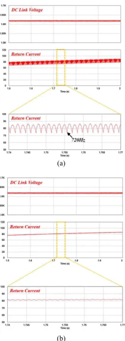
Fig. 5 shows the waveform of the return current of the sub-feeder line with and without the damping resistor in Fig. 3. Fig. 5 (a) shows the waveform of the return current with the damping resistor. The topology with the damping resistor shows that the ripple of the return current oscillates at the 720Hz frequency due to the influence on the output of the 12-pulse diode rectifier. Due to the current path formed by the damping resistor, the applied from the 12-pulse diode rectifier rapidly decreases and this ripple
addition, we propose an optimal damping control algorithm to eliminate the resonance phenomenon caused by the inductive load.
2.2 Proposed optimal damping control algorithm SIV for railway vehicles is resonant at the inverter output stage due to inductive loads such as cooler or compressor motor. In order to suppress such a phenomenon, a control method for compensating DC-link voltage sensing using a Band Pass filter has been studied. However, periodical resonance phenomenon occurs according to the inverter output, so there is a limit to constantly controlling the DC-link voltage value. Fig. 6(a) shows the ground receiving voltage due to the topology of Fig. 3. If the topology of Fig. 3 is used, a noise phenomenon occurs in the actual ground receiving voltage due to the ripple current flowing in the line as shown in Fig. 6(a). If the damping resistor is removed and the optimal damping control is applied to solve this problem, the ground receiving voltage is stabilized as shown in Fig. 6(b). Therefore, it is necessary to remove the damping resistance and apply the optimal damping control algorithm in order to make the auxiliary power supply smaller and lighter.
In this paper, we propose an optimal control algorithm that suppresses resonance phenomenon and maintains steady state by damping control by compensating DC-link voltage resonance component due to load on the q axis voltage of the synchronous frame passing through BPF. In (a)
(b)
Fig. 5. Comparison waveform of sub-feeder retrace current
with or without damping resistance
(a)
(b)
Fig. 6. Ground receiving voltage comparison waveform
due to the current flowing through the line: (a) With damping resistor, (b) Without damping resistor
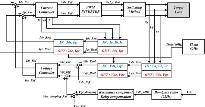
addition, the optimal phase control was performed the q axis voltage of the synchronous reference frame at a point earlier than the point at which the resonance occurs, and to accelerate the steady-state convergence. Fig. 7 shows a band pass filter block diagram for extracting the resonance component of DC-link voltage. The band-pass filter extracts the resonance component using the resonance frequency of 22 Hz obtained through equation (2). This value was derived using the rail vehicle auxiliary power supply parameter. The resonance component extracted through the bandpass filter is applied to the q axis voltage of the synchronous reference frame, which is earlier than the resonance start point, and is used to control the inverter voltage.
1
2p LC (2)
where, L is the SIV input stage inductor and C is the capacitor.
Fig. 8 shows the V2 function with phase advance in V1 and V1 functions. Equation (3) is an equation developed by using the trigonometric function of the V2 function. Using this, the equation (3) can be transformed into a function for V1. Finally, the function V2 can be expressed as a function of V1 and can be applied to optimal damping control by substituting V1 for the resonance component through the bandpass filter in equation (4).
(a)
(b)
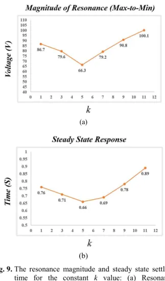
Fig. 9. The resonance magnitude and steady state settling
time for the constant k value: (a) Resonance amplitude, (b) Steady state settling time
0(sin(w22) cos(qD)+cos(w22)sin(qD))
V t t (3) 1 1 ( ) ( )cos(q q ) q sin(q )) q D + D dV V d (4) 22 qD= kw t (5)
Here, w22 represents an angular frequency of 22 Hz.
The phase in equation (4) can be expressed as in equation. (5). The value of k in equation (5) can be varied to obtain the value of resonance and minimized steady state settling time.
Fig. 9 shows the resonance magnitude and steady state settling times for the k variable values derived from the simulation using the SIV parameters of the rail vehicle. In Fig. 10, when k is 5, we can confirm that the resonance magnitude and the steady state reach time are the minimum values. Based on this value, we perform simulation and experiment. Fig. 10 shows the SIV optimal control block diagram for railway vehicles using DTI. The resonant component of the DC-link voltage is detected for optimal control. Considering the parameters of the railway vehicle SIV, the resonance component is extracted through the 22 Hz BPF and the voltage is controlled by applying it to the q
Fig. 7. DTI auxiliary power supply topology without the
DC-DC converter
Fig. 8. Sin wave that is phase ahead of the fundamental
axis voltage of the synchronous reference frame. At this time, in order to reduce the resonance and shorten the settling time, the q axis voltage of the synchronous reference frame is applied before the resonance start point. The current control then causes the inverter to output a three-phase current and derive the voltage to apply to the load [11-13].
3. Simulations
Table 1 shows SIV parameters of the railways used in Seoul Line 2. Simulation and experiments were carried out by parameters of Table 1.
Fig. 11 shows the simulation results according to SIV without damping control. The DC-link voltage has about 1620V in Fig. 11. The q axis voltage of the synchronous reference frame by voltage control without damping control. In addition, the DC-link voltage got resonated and diverged by inductive loads. The resonance of the DC-link voltage generates the noise of the railway vehicle. In addition, DC-link voltage is divergence according to the change of the inductive load. Therefore, the control method without proposed optimal control algorithm could not be applied to railway vehicles that require stability and reliability.
Fig. 12 shows the simulation results in accordance with DTI optimal control algorithm proposed in this paper. The DC-link voltage is maintained at about 1620V.
Fig. 10. Auxiliary power supply optimal control block diagram for railway vehicles using DTI
Table 1. Parameter of auxiliary power supply Parameter Value Capacitor 4200 u Inductor 12 mH Rated voltage DC 1,500 V Input Voltage range DC 900~1,800 V Rated power 190 kVA Rated voltage AC 380 V (+5 %,-10 %)
(Load 0~100 %) Output
Rated frequency 60 Hz ± 1 %
Fig. 12. Simulation results with proposed optimal control
algorithm
When the load is applied, q axis voltage of the synchronous reference frame can be confirmed that the direct-current resonance component is compensated. When applying the proposed algorithm, the resonance of DC-link voltage is eliminated and the q axis voltage of the synchronous reference frame is stabilized. Therefore, the output voltage is also stabilized as well.
Fig. 13 shows a simulation results in the optimal control algorithm is applied when the load changes. The inductive load of the actual railways SIV is occur when using air conditioners and air compressors. The inductive load of air conditioners is gradually applied in two stages. The DC-link voltage in Fig. 13, the load changes in two steps, at this time the resonance component is eliminated twice all within a short time. As a result, output voltage and output current are controlled to normal sine waves.
4. Experimental Results
Experiments were performed to verify the proposed optimal damping control using direct two-level inverter for auxiliary power supply in railway vehicle. The experiment method was the same as the simulation, and the experiments were carried out using the parameters in Table 1.
Fig. 14 and Fig. 15 show the hardware setup. Fig. 14 shows the auxiliary power supply inverter of the rail way vehicle using the topology proposed in this paper. Currently, this inverter is being used for Seoul Line 2 railway vehicle.
Fig. 15 show the measuring instruments for experiment
Fig. 13. Simulation results with proposed optimal control
algorithm according to load changes
Fig. 14. Actual auxiliary power supply of railway vehicle
with proposed DTI
Fig. 16. Experiment results without damping control
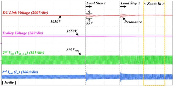
Fig. 17. Experimental results to which the proposed optimal damping control algorithm is applied
inductive load. However, DC-link voltage resonance occurs after starting the inductive load. When the second inductive load is applied, the resonance diverges. In fig. 16, it can be confirmed that the maximum size of resonance is 123V.
Fig. 17 shows the experimental results to which the proposed optimal damping control algorithm is applied. The trolley voltage and DC-link voltage are 1650V and 1650V before starting the inductive load. When an inductive load is started, the resonance of the DC-link voltage is rapidly eliminated. In addition, the maximum magnitude of resonance is 99V. Compared to the experiment results in Fig 14, the proposed method is capable of reducing the resonance magnitude more than at least 20%.
Fig. 18 and Fig. 19 are an enlarged waveform of Fig. 16 and Fig. 17. The output voltage and current voltage have sinusoidal waveforms because of voltage control in inverter. Resonance occurs in the DC-link voltage to which the damping control is not applied, whereas the resonance is removed and the DC-link voltage has constant value in proposed optimal damping control.
5. Conclusion
An optimal damping control algorithm of direct two-level inverter for miniaturization and weight reduction of auxiliary power supply on railway vehicle has been proposed in this paper. DC-DC converter and damping resistance are removed for miniaturization and weight reduction in proposed topology.
The resonance of the DC-link voltage is eliminated by performing the voltage control by adding the resonance component of DC-link voltage to the q axis voltage of the synchronous reference frame. The resonance component of DC-link voltage is extracted by using band pass filter. At this time, in order to reduce the resonance and shorten the settling time, the q axis voltage of the synchronous reference frame is applied before the resonance start point. By using the algorithm proposed in this paper, the resonance is eliminated and the magnitude of the resonance also has decreased. Compared to the resonance of the DC-link voltage without optimal damping control, the proposed method is capable of reducing the resonance magnitude more than at least 20%. The simulation and experiment results show the outstanding performance of the optimal damping control.
Acknowledgements
This research was supported by the Research Grant from Dawonsys through the Korea Agency for Infrastructure Technology Advancement funded by the Ministry of Land, Infrastructure and Transport of the Korean government (Project No.18TBIP-C143153-01).
References
[1] S. Inarida, K. Nakamura, and Y. Iwaji, “Study on Instantaneous Voltage Control Method for Auxiliary Power Supply System Used in Rolling Stocks,” Trans. IEE Japan, vol. 116-D, no. 11, pp. 1132-1139. 1996.
[2] J. S. Kim, st. al., “Instantaneous Voltage Control of Auxiliary Power Supply for Railway Application Using H.G.C and State Feedback,” in Conf. Rec. ICEE’98, vol. 2, pp. 538-541, 1998.
[3] H. J. Shin, Y. J. Park, and Y. J. Son, “Reliability Research through Improvement in Locomotive Auxiliary Power Maintenance,” J. the Korean Society for railway, pp. 795-807, May. 2012.
[4] K. S. Kim, “A Case Study on Failure during Operation of Line 4 Train Auxiliary Power Supply (SIV),” J. the Korean Society for railway, pp. 241-244, Oct. 2017.
[5] S. S. Lee, D. H. Shin, J. M. Kim, Y. C. Kim, and C. Y. Won, “A Study of 20kVA IGBT SIV development and Production for Electric Coache,” in conf. power electronics annual, pp. 309-313, Jul. 1997.
[6] J. S. Kim, J. H. Choi, S. S. Lim, and E. K. Lee, “Instantaneous Voltage Control Scheme of Auxiliary Power Supply System for Electric Railway Vehicles,” Trans. Korean institute of power electronics, vol. 5, no. 5, pp. 349-356, Aug. 1999.
[7] O. Deblecker, A. Moretti, and F. Vallee, “Com-parative study of soft-switched isolated DC-DC converters for auxiliary railway supply,” IEEE Trans. Power Electron., vol. 23, no. 5, pp. 2218-2229, Sep. 2008.
[8] J. Weigel, A. Nagel, and H. Hoffmann, “High voltage IGBTs in medium frequency traction power supply,” presented at the 13th European Conf. on Power Electronics and Applications-EPE, Paper 8040, 2009. [9] I. Quesada, A. Lazaro, C. Martinez, A. Barrado, M. Sanz, C. Fernandez, R. Vazquez, and I. Gonzalez, “Modulation technique for low frequencyharmonic cancellation in auxiliary railway power supplies,” IEEE Trans.Ind. Electron., vol. 58, no. 9, pp. 3976-3987, Sep. 2011.
[10] D. C. Yang, J. W. Kim, and Y. B. Lee, “Resonance Characteristic Improvement of Direct Two-Level Auxiliary Power Supply,” J. the Korean Society for railway, pp. 1398-1403, Oct. 2012.
[11] S. G. Parker, B. P. McGrath, and D. G. Holmes, “Regions of active damping control for LCL filters,” in Proc. IEEE Energy Conver. Congr. Expo., pp. 53-60, 2012.
[12] J. C. Wiseman and B. Wu, “Active damping control of a high-power PWM current-source rectifier for line-current THD reduction,” IEEE Trans. Ind. Electron., vol. 52, no. 3, pp. 758-764, Jun. 2005. [13] N. Choudhary and D. Kaur, “Vibration Damping
ering from the Chungbuk University, Korea, in 2001 and 2003. He is currently working toward his Ph.D. degree at Hanyang University, Seoul, Korea. Since 2011, he has been a leader of innovation R&D center the Dawonsys, Ansan, Korea. His current research interests include power converters control and electricfied railway system.
Ju Lee He received his M.S. degree
from Hanyang University, Seoul, South Korea, in 1988, and his Ph.D. from Kyusyu University, Japan in 1997, both in Electrical Engineering, He joined Hanyang University in September, 1997 and is currently a Professor of the Division of Electrical and Biomedical Engineering. His main research interests include electric machinery and its drives, electromagnetic field analysis, new transformation systems such as hybrid electric vehicles (HEV), and high-speed electric trains and standardization. He is a member of the IEEE Industry Applications Society, Magnetics Society, and Power Electronics Society.