Simulation of an X-ray Radiography for the Coating Thickness Measurement
in the TRISO-coated Fuel Particle
Woong Ki Kim,aYoung Woo Lee,a Ji Yeon Park,a andSung Woong Ra,b
a Korea Atomic Energy Research Institute, 150 Duk-jin Dong, Yusong, Daejon, wkkim@kaeri.re.kr
b Chungnam National Univ., 220 Goong Dong, Yusong, Daejon, swra@cnu.ac.kr
1. Introduction
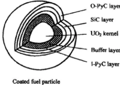
TRISO(Tri-Isotropic) as well as BISO(Bi-Isotropic) is a typical coated fuel particle for the HTGR(high temperature gas-cooled reactor), one of the high efficient Generation IV reactors. TRISO fuel particle is widely applied for it's higher stability for a high temperature and is known for a more efficient retention capability for fission products. The typical ball typed TRISO fuel particle with a diameter of about 1 mm is composed of a nuclear fuel particle as a kernel with a diameter of 0.35~0.6 mm in the center core and outer coating layers. The coating layers consist of a buffer PyC(pyrolytic carbon) layer, inner PyC(IPyC) layer, SiC layer, and outer PyC(OPyC) layer as shown in Figure 1.[1~6]
Figure 1. The structure of a TRISO-coated fuel particle
The quality of the TRISO fuel particle is closely related with the fuel performance and safety. A variety of inspection items are involved in the specification of TRISO fuel. Most of the items depend on destructive methods, but a few items can be inspected by nondestructive methods.[7, 8] Recently, X-ray radiography or X-ray CT methods are being applied to nondestructively measure some parameters involving the thickness of coating layers in USA, China, Japan, and Germany.[2, 7~10].
The destructive method is very accurate, but it is difficult to prepare test samples. Measurement error can be induced by a variation of the position of a cut surface. Above all, destructive test samples must be minimized in the fabrication process due to the generation of radioactive wastes during the test procedures.
To overcome the disadvantages of the destructive technique, nondestructive methods have been developded to measure the thickness of the coating layers of the TRISO fuel particle.
2. Thickness Calculation of the Coating Layers
Fuel particle can be projected by a fan beam as shown in Figure 2. Here, the center of the fan beam goes through the center of a fuel particle. The central projection line is perpendicularly projected to the center of a virtual screen. Fan beam projection profile is represented by pixel values on a one-dimensional line array on the screen. The radius of each layer can be calculated by equation (1) using the measured distances, d1, d2, , , d5, for the projection image on the screen.
Figure 2. Projection of TRISO by a fan beam
rn = dn R/√ (D2
+dn2), n=1, 2, 3, 4, 5 (1) Where,
D : distance from source to screen
R : distance from source to the center of a particle r1 : radius of kernel
r2~r5 : radius of buffer PyC, IPyC, SiC, OPyC layer d1 : measured distance for radius of kernel d2~d5: measured distance for radius of buffer, IPyC, SiC, OPyC layer
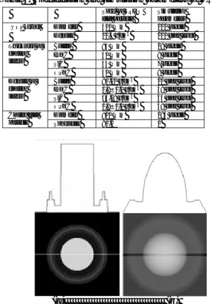
3. Simulation for the TRISO-coated Fuel Particle The simulation parameters were established based on the specification as shown in Table 1. Image plane consists of 256x256 pixels and 256 gray levels(8 bit resolution) per pixel. The cross section of the virtual TRISO fuel generated from the simulation parameters as shown in Figure 3(a). Figure 3(b) shows the projection image projected by the virtual fan beam and the intensity profile on the center line. The intensity profile of the cross section is clear for the classified density parameters, but the projection image was blurred by the accumulated density parameters. The
Transactions of the Korean Nuclear Society Autumn Meeting Busan, Korea, October 27-28, 2005
quality of the real X-ray projection image will be much worse than that of the simulated projection image because of the large focus size of the X-ray generator and the induced noises in the detector. It is not easy to establish boundary lines on the blurred projection image. Image processing technique was helpful to improve the acquired image and to establish the boundary lines.
Table 1. Specification and simulation parameters of TRISO
(a) (b)
Figure 3. (a)Intensity profile for cross section, (b)Intensity profile for projection image of virtual TRISO fuel particle
4. Measurement of the Thickness of Coating Layers The distance from the center point to the boundary lines, dn, was acquired for the projection image on screen. Each radius rn was computed by the equation (1). Here, D=512(pixels), R=384(pixels). The kernel diameter and the thickness of the coating layers were measured by using the radius rn. The measurement error ranged from -2.08 µm to 2.7 µm. The error rate ranged from -5.20 to 5.46 %. The measurement error for the diameter of the kernel was so small. But the error for the thickness of the coating layers was about 5% because the boundary lines for the coating layers were not clear. The boundary lines should be carefully established for the coating layers to reduce the measurement error.
5. Conclusion
In this study, the core diameter and the thickness of a coating layer were effectively measured by using a 2D
X-ray radiographic simulation. The experimental results are as follows.
- Fan beam typed X-ray radiography was simulated for the TRISO fuel.
- Projection image with blurred boundary lines was acquired. The image was enhanced by adjusting the brightness and contrast.
- The core diameter and the thickness of the coating layers were measured by an exact solution. The error rate was less than 6%.
The thickness of the TRISO fuel coating layers can be nondestructively measured by applying the measurement procedure developed in this study for the X-ray radiographic image.
ACKNOWLEDGEMENTS
This project has been carried out under the Nuclear R&D Program of the Korean Ministry Of Science & Technology.
REFERENCES
[1] Ji Yeon Park, Weon Ju Kim, Young Woo Lee and Jong Hwa Chang, Development of TRISO coating process for HTGR fuel, KAERI/AR-652/2002, 2002. 12
[2] Kazuhiro Sawa, Shuichi Suzuki and Shusaku Shiozawa, Safety Criteria and Quality Control of HTTR fuel, Nuclear Engineering and Design 208, pp.305-313, 2001
[3] Guenter Lohnert, Topical issue on "Japan's HTTR", Nuclear Engineering and Design, 233, pp.1-3, 2004
[4] Masuro Ogawa and Tetsuo Nishihara, Present status of energy in Japan and HTTR project, Nuclear Engineering and Design, 233, pp.5-10, 2004
[5] Kazuhiro Sawa and Shohei Ueta, Research and Development on HTGR fuel in the HTTR project, Nuclear Engineering and Design 233, pp.163-172, 2004
[6] Xioming FU, Masashi TAKAHASHI, Shouhei UETA and Kazuhiro SAWA, Comparison of HTGR Fuel Design, Manufacture and Quality Control Methods between Japan and China, JAERI-Tech, 2002-049, 2002
[7] Chunhe Tang, Yaping Tang, Junguo Zhu, Xueliang Qiu, Jihong Li and Shijiang Xu, Research and Development of Fuel Element for Chinese 10MW High Temperature Gas-cooled Reactor, Journal of Nuclear Science and Technology, Vol.37, No.9, pp.802-806, September 2000.
[8] Chunhe Tang, Yaping Tang, Junguo Zhu, Yanwen Zou, Jihong Li and Xiaojun Ni, Design and manufacture of the fuel element for the 10 MW high temperature gas-cooled reactor, Nuclear Engineering and Design 218, pp.91-102, 2002 [9] John Hunn, Coated Particle Fuel Characterization Lab for the Advanced Gas Reactor Fuel Development and Qualification Program, ANS/GLOBAL 2003. 11
[10] Ronald L. Hockey, Leonard J. Bond, Charles R. Batishko, Joseph N. Gray, John J. Saurwein and Richard A. Lowden, Advances in Automated QA/QC for TRISO Fuel Particle Production, Proceedings of ICAPP 2004, June 2004
Spec. of TRISO fuel particle Simulation parameters Diameter 500 μ m 100 pixels UO2 kernel
Density 10.5 g/cm3 210 gray level
Buffer 95 μ m 19 pixels IPYC 40 μ m 8 pixels SiC 35 μ m 7 pixels Thickness of coating layers OPYC 40 μ m 8 pixels Buffer <1.10 g/cm3 20 gray level IPYC 1.9±0.1 g/cm3 38 gray level
SiC >3.18 g/cm3 64 gray level
Density of coating layers
OPYC 1.9±0.1 g/cm3 38 gray level
Diameter 920 μ m 184 pixels Coated fuel